Lunar Reconnaissance Orbiter
Diviner Lunar Radiometer Experiment
Experiment
Data Record
Software
Interface Specification
Version 1.8
December
10, 2009
Prepared
by:
Mark
Sullivan
UCLA
Approved
by:
________________________________
David Paige
UCLA
Principal Investigator, DLRE
________________________________ ______________________
Raymond
Director, PDS Geosciences Node PDS Program
Manager

CHANGE LOG
|
DATE |
SECTIONS CHANGED |
REASON FOR CHANGE |
REVISION |
|
3/14/07 |
All |
First draft |
Draft v1.0 |
|
6/1/07 |
1.3, 2.2, 2.3.4, 3.1, 3.2, 3.3,
Appendix A, Appendix B |
Pre-review suggestions. |
Draft v1.1 |
|
8/1/07 |
1.3, 2.2, 2.3.4, 2.4.2, 3.1, 3.2, 3.3,
Appendix A, Appendix B |
Post-review |
Draft v1.2 |
|
8/23/07 |
2.2, 3.2, 3.3, Appendix A |
Post-post-review |
Draft v1.3 |
|
5/16/08 |
3.3, Appendix A |
Minor Edits |
Draft v1.4 |
|
1/18/09 |
2.3.4, 3.3, Appendix A |
Minor Edits |
Draft v1.5 |
|
6/1/09 |
3.3, Appendix A |
Minor Edits |
Draft v1.6 |
|
12/1/09 |
3.3, Appendix A |
Minor Edits |
Draft v1.7 |
|
12/10/09 |
3.3, Appendix A |
Minor Edits |
Draft v1.8 |
TABLE OF CONTENTS
1. INTRODUCTION........................................................................................................... 6
1.1 Purpose and Scope............................................................................................... 6
1.2 Contents.................................................................................................................. 6
1.3 Applicable Documents and Constraints.............................................................. 6
1.4 Relationships with Other Interfaces...................................................................... 7
2. DATA PRODUCT CHARACTERISTICS
AND ENVIRONMENT............................ 7
2.1 Instrument Overview............................................................................................... 7
2.2.1 Hardware Overview......................................................................... 7
2.2 Data Product Overview....................................................................................... 10
2.3 Data Processing.................................................................................................. 10
2.3.1 Data Processing Level................................................................. 10
2.3.2 Data Product Generation............................................................. 11
2.3.3 Data Flow....................................................................................... 11
2.3.4 Labeling and Identification........................................................... 12
2.4 Standards Used in Generating Data Products................................................. 12
2.4.1 PDS Standards............................................................................. 12
2.4.2 Time Standards............................................................................. 12
2.4.3 Coordinate Systems..................................................................... 12
2.4.4 Data Storage Conventions........................................................... 13
2.5 Data Validation.................................................................................................... 13
3. DETAILED DATA PRODUCT SPECIFICATIONS............................................ 13
3.1 Data Product Structure and Organization......................................................... 13
3.2 Data Format Descriptions.................................................................................. 13
3.3 Label and Header Descriptions......................................................................... 19
4. APPLICABLE SOFTWARE...................................................................................... 21
4.1 Utility Programs.................................................................................................... 21
APPENDIX A - EXAMPLE OF A
DIVINER EDR LABEL.......................................... 23
APPENDIX B – ADDITIONAL FIELD
DESCRIPTIONS............................................ 25
ACRONYMS AND
ABBREVIATIONS
|
ASCII |
American Standard Code for Information
Interchange |
|
CODMAC |
Committee on Data Management and
Computation |
|
DLRE |
Diviner Lunar Radiometer Experiment |
|
DREB |
Diviner Remote Electronics Box |
|
EDR |
Experiment Data Record |
|
ICD |
Interface Control Document |
|
JPL |
Jet Propulsion Laboratory |
|
Kbyte |
Kilobytes |
|
LRO |
Lunar Reconnaissance Orbiter |
|
MB |
Mega Bytes |
|
NASA |
National Aeronautics and Space
Administration |
|
ODL |
Object Description Language |
|
PDS |
Planetary Data System |
|
RAM |
Random Access Memory |
|
RDR |
Reduced Data Record |
|
SFDU |
Standard Formatted Data Unit |
|
SIS |
Software Interface Specification |
|
SOC |
|
|
TBD |
To Be Determined |
|
TDS |
Telemetry Delivery Subsystem |
|
URL |
Universal Resource Locator |
GLOSSARY
|
TERM |
DEFINITION |
|
Meta-Data |
Selected or summary information about
data. PDS catalog objects and data product labels are forms of meta-data for
summarizing important aspects of data sets and data products. |
|
Profile |
The vertical distribution, as a
function of atmospheric altitude, of some physical property, such as
temperature or water vapor amount |
The purpose of this data product Software Interface Specification (SIS) is to provide users of the Diviner Lunar Radiometer Experiment (DLRE or “Diviner”) Experiment Data Record (EDR) with a detailed description of the product and a description of how it was generated, including data sources and destinations. The document is intended to provide enough information to enable users to understand the Diviner EDR data product. The users for whom this document is intended are software developers of the programs used in generating the EDR products and scientists who will analyze the data, including those associated with the Lunar Reconnaissance Orbiter (LRO) Project and those in the general planetary science community.
This data product SIS describes how the LRO Diviner instrument acquires its data, and how the data are processed, formatted, labeled, and uniquely identified. This document discusses standards used in generating the product and software that may be used to access the product. The data product structure and organization is described in sufficient detail to enable a user to read the product. Finally, an example of a product label is provided.
1.3 Applicable Documents and Constraints
This data product SIS is responsive to the following LRO
documents:
1. Lunar Reconnaissance Orbiter Project Data Management and Archive Plan, K. North, LRO Document 431-PLAN-00182.
2. Diviner Lunar Radiometer Experiment Telemetry Dictionary, S. M. Loring, JPL D-33198.
3.
Lunar Reconnaissance
Orbiter Diviner Science Team and PDS Geosciences Node Interface Control
Document (ICD),
This SIS is also consistent with the following Planetary Data System documents:
4. Planetary Data System Archive Preparation Guide, Version .050503, JPL D-31224, May 3, 2005.
5. Planetary Data System Data Standards Reference, Version 3.7, JPL D-7669, Part 2, March 20, 2006.
6. Planetary Science Data Dictionary Document, JPL D-7116, August 28, 2002.
1.4 Relationships with Other Interfaces
The Experiment Data Record products described in this SIS
are used in the production of other archived products of the Lunar
Reconnaissance Orbiter (LRO) mission, so that changes to their content and
format may result in an interface impact. In particular, the Diviner Reduced
Data Record (RDR) products take EDR products as their input data sets.
2. DATA PRODUCT CHARACTERISTICS AND ENVIRONMENT
The Diviner Lunar Radiometer Experiment is in most respects a copy of the Mars Climate Sounder (MCS) instrument on Mars Reconnaissance Orbiter. Both instruments observe radiation with 21 detectors in each of nine spectral bands. MCS is primarily an atmospheric limb sounder that measures temperature, pressure, water vapor, dust, and condensates at Mars’ atmospheric limb. In contrast, Diviner is a surface pushbroom mapper that measures emitted thermal radiation and reflected solar radiation from the surface of the moon. Two Diviner solar channels measure 0.3-3 μm reflected solar radiation. Three Diviner channels near 8 μm classify regolith mineralogy by mapping the location of the Christiansen feature. The remaining four Diviner channels measure surface temperature in four spectral bands ranging from 12.5 μm to beyond 200 μm.
The Diviner Lunar Radiometer Experiment is a nine channel infrared radiometer employing filter radiometry. These channels are distributed between two identical, boresighted telescopes, and an articulated elevation/azimuth mount allows the telescopes to view the lunar surface, space, and calibration targets. The instantaneous field-of-view (FOV) response of each channel is defined by a linear, 21-element, thermopile detector array at the telescope focal plane, and its spectral response is defined by a focal plane bandpass filter.
The Diviner structure consists of an instrument optics bench assembly (OBA), an elevation/azimuth yoke, and an instrument mount. The OBA contains all of the instrument optical subassemblies, and is suspended from the yoke (Figure 1). Elevation and azimuth motors mounted on the yoke drive instrument articulation. The OBA can be temperature controlled, and internal temperature gradients are minimized by design. Radiometric calibration is provided by views of blackbody and solar targets mounted on the yoke. The electronics subassemblies control signal processing, instrument operation and articulation, command processing, and data processing. These electronics are distributed between the OBA and the yoke. Figure 1 shows a schematic diagram of the mechanical configuration of the instrument with the major components indicated. Figure 2 gives a schematic representation of the optical layout.
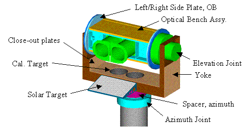
Figure 1 Instrument Configuration
Figure 2 Optics Assembly
(Telescopes A & B)
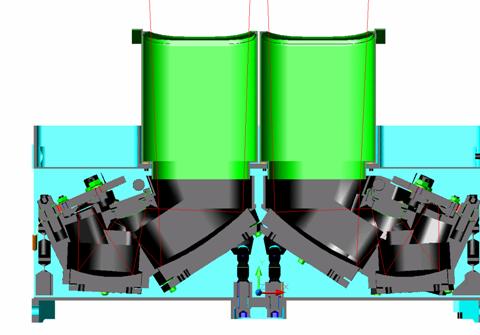
Figure 2 Optical Layout. Telescope A (left) and Telescope B (right)

Figure 3 Diviner channel spectral characteristics
Figure 3 lists the channel bandpasses and functions. The detector arrays for channels A1 through A6 are located in the focal plane of telescope A. The detector arrays for channels B1 through B3 are located in the focal plane of telescope B. Each Diviner spectral channel has 21 FOVs defined by the individual detectors of the corresponding linear array. Individual detector FOV dimensions, linear array length and linear array spacing in both focal planes is specified in Figure 4.
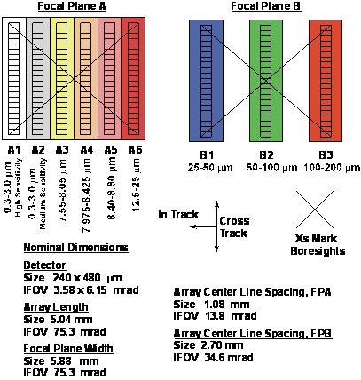
Figure 4 Detector and Filter Layout
Every 2.048 seconds Diviner collects a data “frame” containing the following:
· 16 sets of science data, with each set containing 192 sixteen-bit science measurements from the focal plane interface electronics obtained over integration periods of 0.128 seconds
· A single set of instrument engineering and housekeeping measurements (or “engineering data”)
The data are downlinked to the LRO Ground Data System (GDS) and are pushed to the Diviner SOC at the end of each downlink pass. Diviner software assembles the telemetry files into EDR data tables, each covering a one-hour time period.
Each Diviner EDR data product will consist of two files. The first file is an ASCII formatted detached PDS label. The second file is the ASCII data table file.
Each ASCII record contains 2656 bytes, and there will be a record every 0.128 seconds (unless there is a data gap; time periods which contain no data will not produce data records). Each one-hour Diviner EDR ASCII data table will be up to approximately 75 MB. The volume of the EDR data product will be up to approximately 1800 MB per day.
While there is only a single set of engineering data for the 16 sets of science data, it is known during which of the 16 science data sets a given engineering measurement was taken. In the EDR, the engineering data are propagated across each science data set for a completely uniform and flat file. Each engineering measurement will contain a valid value during the appropriate science data set, and the UNKNOWN_CONSTANT (-9999) during the other science data sets where engineering data were not obtained.
In the ASCII data tables, each complete set of science data
plus engineering data is considered a “record”, and is contained on a single
line. Where a data measurement is not
valid or applicable, the UNKNOWN_CONSTANT will be found.
This document uses the Committee on Data Management and Computation (CODMAC) data level numbering system to describe the processing level of the EDR data product. Diviner EDR data products are considered CODMAC “Level 2”, equivalent to NASA level 0. The EDR data files are generated from CODMAC Level 1 or “Raw Data”, which are the telemetry packets within the project specific Standard Formatted Data Unit (SFDU) record. Refer to the following table for a definition of the CODMAC and NASA data processing levels.
Processing Levels for Science Data Sets
|
NASA |
CODMAC |
Description |
|
Packet data |
Raw – Level 1 |
Telemetry data stream as received at
the ground station, with science and engineering data embedded. |
|
Level 0 |
Edited – Level 2 |
Instrument science data (e.g., raw
voltages, counts) at full resolution, time ordered, with duplicates and
transmission errors removed. |
|
Level 1A |
Calibrated - Level 3 |
Level 0 data that have been located in space
and may have been transformed (e.g., calibrated, rearranged) in a reversible
manner and packaged with needed ancillary and auxiliary data (e.g., radiances
with the calibration equations applied). |
|
Level 1B |
Resampled - Level 4 |
Irreversibly transformed (e.g.,
resampled, remapped, calibrated) values of the instrument measurements (e.g.,
radiances, magnetic field strength). |
|
Level 2 |
Derived - Level 5 |
Geophysical parameters, generally
derived from Level 1 data, and located in space and time commensurate with
instrument location, pointing, and sampling. |
|
Level 3 |
Derived - Level 5 |
Geophysical parameters mapped onto
uniform space-time grids. |
The
Diviner EDR data products will be generated by the Diviner Instrument Team at
JPL. The EDR data products will be reconstructed from telemetry data products
and formatted according to this EDR SIS. Meta-data acquired from the telemetry
data headers will be used to populate the PDS label. The PDS archives will be
assembled and delivered to the PDS from UCLA.
Diviner science and engineering telemetry are transferred to the Diviner JPL SOC. Once transferred, the Diviner software automatically processes the telemetry into Level 0 EDR data products. The Diviner EDR data products are then archived locally at the Diviner operation center.
After an initial data validation period, the Diviner team will assemble the data products and ancillary files into archive volumes and will transfer the assembled volume to the PDS Geosciences Node. The Diviner EDR archive will be made available via data releases scheduled at three month intervals as specified in the Lunar Reconnaissance Orbiter Project Data Management and Archive Plan (see Applicable document #1).
2.3.4 Labeling and Identification
The data set ID provided by the PDS for the Diviner EDR data product is:
LRO-L-DLRE-2-EDR-V1.0. The version number is incremented should the entire EDR data set be revised. The data set name is “LRO DLRE LEVEL 2 EDR V1.0”.
The file naming convention for the Diviner data products will be in the form of an 8 digit date in the format YYYYMMDD, plus a two-digit hour, e.g. “2007070820_EDR.TAB". The hour represents the beginning of the one-hour period in which the data were taken. (Please note that some records may contain times that fall slightly outside of the one-hour range. This is due to the desire to keep all records that arrive in the same data frame together in the same file. Thus records may have a time of just before the hour given in the file name, or just after the end of said hour, to a maximum difference of 2.048 seconds.)
Each Diviner EDR data product has a detached PDS label in a separate file of the same name, extension .LBL: e.g. “2007070820_EDR.LBL”. The PDS format file for each EDR data product will be DLRE_EDR.FMT.
2.4 Standards Used in Generating Data Products
The Diviner EDR complies with Planetary Data System standards for file formats and directory names, PDS labels, as specified in the PDS Standards Reference [5] and the Planetary Science Data Dictionary Document [6].
The PDS label for a Diviner EDR uses keywords denoting time values, such as start time, stop time, start spacecraft clock count, and stop spacecraft clock count. Each time value standard is defined according to the PDS keyword definition.
In the data product label, Start Time and Stop Time values are stored in PDS compliant UTC date format, in the pattern YYYY-MM-DDTHH:MM:SS.SSS (four digit year, two digits for month, day, hour, minute and second, and three digits for decimal fractional second). Spacecraft clock start and stop count time values are stored in decimal seconds from the epoch January 1, 2001 00:00:00 UTC.
The Diviner EDR is a low-level data product, and as such
contains no geometry/geolocation information.
For this reason, no spatial coordinate systems are used, nor are any
coordinate system conventions required.
2.4.4 Data Storage Conventions
The Diviner EDR data
files are stored as fixed-length fixed-format ASCII tables. The detached PDS
labels for Diviner EDR's are stored as ASCII text. Each record is terminated with a
carriage return followed by a line feed.
Diviner EDR products will be validated before being released to the PDS. Validation is accomplished in two parts: validation for scientific integrity and validation for compliance with PDS standards. Diviner Team members are expected to conduct validation for scientific integrity in the course of their analysis of the products. Science validation is meant to ensure that data products contain the expected measurements and that they are otherwise suitable for analysis. The details of the science validation process are the responsibility of the Diviner Team.
Validation for PDS compliance will be performed by the PDS Geosciences Node and is meant to ensure that data products conform to PDS standards and to the specifications in this SIS.
A data set must also pass a peer review before it is accepted by PDS. The Diviner Team and the PDS Geosciences Node will convene a peer review committee made up of scientists and data engineers. The committee will examine the data set to make sure it is complete and meets the product specifications as defined in the SIS. The committee will include a PDS representative to ensure that the data set is in compliance with PDS standards.
3. DETAILED DATA PRODUCT SPECIFICATIONS
3.1 Data Product Structure and Organization
The EDR data products will be located in the DATA directory of the EDR volume. The files will be grouped into directories with one directory per day. Each directory name will be in the format YYYYMMDD. Within each directory there will be up to 24 data product files and their labels, with each file/label corresponding to a one-hour time period. The labels will point to the corresponding data files, and contain a pointer to the format file detailing the column layout of the data files. The data product file names will be in the format YYYYMMDDHH_EDR.TAB for the data tables, and YYYYMMDDHH_EDR.LBL for the labels.
The Diviner EDR data product file is a fixed record-length
ASCII table. Descriptions of the data contained within the table columns are
provided below. For descriptions of
starting byte and column lengths, please see the format file included within
the volume.
LRO Diviner Measurement
Data Components
|
Column # |
Name |
Data Type |
Description |
|
1 |
Q |
ASCII_INTEGER |
A quality
indicator: ‘#’ is comment, ‘0’ is good
data, ‘1’ is column heading, and >2 is bad data. |
|
2 |
DATE |
CHARACTER |
Date at the
midpoint of observation (SCET, UTC) |
|
3 |
UTC |
CHARACTER |
Time at the
midpoint of observation (SCET, UTC) |
|
4 |
SCLK |
ASCII_REAL |
Decimal spacecraft
clock at the midpoint time of observation |
|
5 |
SOUNDING |
ASCII_INTEGER |
Sounding number in
the current set of ten packets. Range
is 1-16. |
|
6 |
FROM_PKT |
ASCII_INTEGER |
Packet count of the
packet this sounding began in. |
|
7 |
PKT_COUNT |
ASCII_INTEGER |
The number of
packets, including the current one, sent since bootup |
|
8 |
SAFING |
ASCII_INTEGER |
A 1-bit value
indicating Safing; '1' indicates that the instrument has started safing but
hasn't yet finished. |
|
9 |
SAFED |
ASCII_INTEGER |
A 1-bit value
indicating Safed; '1' indicates that the instrument was stowed during this
observation; flight software will not move the actuators until a resume
command has been received. |
|
10 |
FREEZING |
ASCII_INTEGER |
A 1-bit value
indicating Freezing; '1' indicates that the instrument was moving to a valid
frozen position during this observation. |
|
11 |
FROZEN |
ASCII_INTEGER |
A 1-bit value
indicating Frozen; '1' indicates that the instrument was frozen during this
observation: flight software will not move the actuators (except to safe)
until a free command has been received. |
|
12 |
ROLLING |
ASCII_INTEGER |
A 1-bit value
indicating Rolling; '1' indicates that the data was taken during a
non-nadir-pointed or “rolling” attitude.
Enabled by command. |
|
13 |
DUMPING |
ASCII_INTEGER |
A 1-bit value
indicating Dumping memory; '1' indicates that the packet contains dump data
instead of science data. Enabled by
command. |
|
14 |
MOVING |
ASCII_INTEGER |
A 1-bit value
indicating Actuator motion; '1' indicates that an actuator moved during
acquisition of the packet's science data. |
|
15 |
TEMP_FAULT |
ASCII_INTEGER |
A 1-bit value indicating
stepper temperature fault; '1' indicates that an over-temperature condition
was detected in the actuator-controlling chip. |
|
16 |
MODE |
CHARACTER |
An 8-bit value
indicating various conditions. See
Appendix B of DLRE EDR SIS for details. |
|
17 |
SC_TIME_SECS |
ASCII_INTEGER |
The seconds portion
of SCLK in the last time message received. |
|
18 |
SC_TIME_SUBS |
ASCII_INTEGER |
The subseconds
portion of SCLK in the last time message received. |
|
19 |
TICKS_PKT_START |
ASCII_INTEGER |
The number of 31.25
Hz Diviner fine-time pulses received since bootup, at the time of packet
assembly |
|
20 |
TICKS_AT_SC_TIME |
ASCII_INTEGER |
The number of 31.25
Hz Diviner fine-time pulses received since bootup, as of the last time a time
message from the spacecraft was processed |
|
21 |
RAM_CRC |
CHARACTER |
The most recently
calculated CRC (Cyclic Redundancy Check).
Normally this will be calculated over RAM (the jumptable, the scan
tables, and any uploaded patches). |
|
22 |
FSW_VERSION |
CHARACTER |
The version of
flight software currently running.
Interpreted as a hex number, the first digit is the major release, and
the second digit is the minor release.
The flight build is 30 hex, that is, major release 3 and minor release
0 |
|
23 |
RESET_COUNT |
ASCII_INTEGER |
The number of times
the processor has rebooted since power was applied. Includes watchdog resets and hardware
resets, as well as commanded reboots. |
|
24 |
MISSING_TIMES |
ASCII_INTEGER |
The number of times
since boot that no time command was received from the spacecraft during the
expected window |
|
25 |
OST_INDEX |
ASCII_INTEGER |
The current index
into the Orbit Schedule Table. This is -1 at bootup, and then increments by
one with each equator crossing, as announced by the spacecraft through the
DLRE_EQX command. After index 11, it
wraps around to 0. |
|
26 |
EST_INDEX |
ASCII_INTEGER |
The index into the
current Event Schedule Table.
Increments as each table entry (a Scan Sequence Table) is
completed. Remains at the last value
without looping back to the first.
Range is 0 – 119. |
|
27 |
SST_INDEX |
ASCII_INTEGER |
The index into the
current Scan Sequence Table, which determines the current pointing. Range is 0 – 127. |
|
28 |
LAST_AZ_CMD |
ASCII_INTEGER |
The last azimuth
commanded, in steps, which if the actuator isn't moving, is the same as the
current azimuth. Valid range is 1000 –
3673, which corresponds to 270 degrees at 0.10101 degrees per step. |
|
29 |
LAST_EL_CMD |
ASCII_INTEGER |
The last elevation
commanded, in steps, which, if the actuator isn't moving, is the same as the
current elevation. Valid range is 1000
– 3673, which corresponds to 270 degrees at 0.10101 degrees per step. |
|
30 |
FPA_TEMP |
ASCII_INTEGER |
The temperature
readout of the focal plane A temperature sensor, in data numbers |
|
31 |
FPB_TEMP |
ASCII_INTEGER |
The temperature
readout of the focal plane B temperature sensor, in data numbers |
|
32 |
BAFFLE_A_TEMP |
ASCII_INTEGER |
The temperature
readout of the baffle A temperature sensor, in data numbers |
|
33 |
BAFFLE_B_TEMP |
ASCII_INTEGER |
The temperature
readout of the baffle B temperature sensor, in data numbers |
|
34 |
BB_1_TEMP |
ASCII_INTEGER |
The temperature
readout of the blackbody 1 temperature sensor, in data numbers |
|
35 |
OBA_1_TEMP |
ASCII_INTEGER |
The temperature
readout of the optical bench assembly 1 temperature sensor, in data numbers |
|
36 |
ROTATING_VALUE_1 |
ASCII_INTEGER |
The temperature or
voltage readout in DN of the sensor referenced by 'Rotating temp/voltage
index #1' |
|
37 |
ROTATING_VALUE_2 |
ASCII_INTEGER |
The temperature or
voltage readout in DN of the sensor referenced by 'Rotating temp/voltage
index #2' |
|
38 |
ROTATING_INDEX_1 |
ASCII_INTEGER |
The index of the first
rotating sensor value contained in this telemetry packet. See Appendix B of DLRE EDR SIS for details. |
|
39 |
ROTATING_INDEX_2 |
ASCII_INTEGER |
The index of the
second rotating sensor value contained in this telemetry packet. See Appendix B of DLRE EDR SIS for details. |
|
40 |
ERROR_TIME |
ASCII_INTEGER |
The Diviner
FSW-internal value of SCLK, at the time of the most recent error |
|
41 |
ERROR_ID |
ASCII_INTEGER |
The error ID
associated with the most recent error.
See Appendix B of DLRE EDR SIS for details. |
|
42 |
ERROR_DETAIL |
CHARACTER |
Three bytes
containing up to three additional bytes of information describing the most
recent error condition. See Appendix B of
DLRE EDR SIS for details. |
|
43 |
ERROR_COUNT |
ASCII_INTEGER |
The number of
errors that have occurred since last reboot |
|
44 |
COMMANDS_RECEIVED |
ASCII_INTEGER |
The number of
commands received since bootup. Spacecraft time commands are only counted if
rejected. |
|
45 |
COMMANDS_EXECUTED |
ASCII_INTEGER |
The number of
commands successfully executed since bootup.
This plus the number of commands rejected should equal the number of
commands received, unless one of the commands received is still executing. |
|
46 |
COMMANDS_REJECTED |
ASCII_INTEGER |
The number of
commands received but not successfully executed, since bootup. This plus the number of commands executed
should equal the number of commands received, unless one of the commands
received is still executing. |
|
47 |
LAST_COMMAND_REC |
CHARACTER |
The last command
received, as an 8-byte descriptor.
Commands are saved regardless of their validity See Appendix B of DLRE
EDR SIS for details. |
|
48 |
CMD |
ASCII_INTEGER |
The first byte of
LAST_COMMAND_REC, indicating which of the seven types of DLRE command was
last received. See Appendix B of DLRE
EDR SIS for details. |
|
49 |
REQ_ID |
CHARACTER |
The second byte of
LAST_COMMAND_REC. For command type 3,
DLRE_REQUEST, this is the request ID.
See Appendix B of DLRE EDR SIS for details. |
|
50 |
LAST_TIME_COMMAND |
ASCII_INTEGER |
The spacecraft time
when the last command was received, regardless of whether or not the command
was valid. |
|
51 |
LAST_EQX_PREDICTION |
ASCII_INTEGER |
The last equator
crossing prediction received from the spacecraft, in SCLK. This time may not be the same as the time
of the last equator crossing, if the spacecraft missed sending one or more. |
|
52 |
DREB_MODE |
CHARACTER |
An 8-bit value
indicating various conditions. See
Appendix B of DLRE EDR SIS for details. |
|
53 |
DREB_RAM_CRC |
CHARACTER |
From DREB, the most
recently calculated CRC (Cyclic Redundancy Check). Normally this will be calculated over RAM
(the jumptable, the scan tables, and any uploaded patches). |
|
54 |
DREB_FSW_VERSION |
CHARACTER |
From DREB, the
version of flight software currently running.
Interpreted as a hex number, the first digit is the major release, and
the second digit is the minor release.
The flight build is 30 hex, that is, major release 3 and minor release
0. |
|
55 |
DREB_RESET_COUNT |
ASCII_INTEGER |
From DREB, the
number of times the processor has rebooted since power was applied. Includes watchdog resets and hardware
resets, as well as commanded reboots. |
|
56 |
DREB_MISSING_TIMES |
ASCII_INTEGER |
From DREB, the
number of times since boot that no time command was received from the
spacecraft during the expected window. |
|
57 |
DREB_ERROR_TIME |
ASCII_INTEGER |
From DREB, the
Diviner FSW-internal value of SCLK, at the time of the most recent error. |
|
58 |
DREB_ERROR_ID |
ASCII_INTEGER |
From DREB, the
error ID associated with the most recent error. See Appendix B of DLRE EDR SIS for details. |
|
59 |
DREB_ERROR_DETAIL |
CHARACTER |
From DREB, three
bytes containing up to three additional bytes of information describing the
most recent error condition. See Appendix B of DLRE EDR SIS for details. |
|
60 |
DREB_ERROR_COUNT |
ASCII_INTEGER |
From DREB, the
number of errors that have occurred since last reboot |
|
61 |
DREB_COMMANDS_RECEIVED |
ASCII_INTEGER |
From DREB, the
number of commands received since bootup. Spacecraft time commands are only
counted if rejected. |
|
62 |
DREB_COMMANDS_EXECUTED |
ASCII_INTEGER |
From DREB, the
number of commands successfully executed since bootup. This plus the number of commands rejected
should equal the number of commands received, unless one of the commands
received is still executing. |
|
63 |
DREB_COMMANDS_REJECTED |
ASCII_INTEGER |
From DREB, the
number of commands received but not successfully executed, since bootup. This plus the number of commands executed
should equal the number of commands received, unless one of the commands
received is still executing. |
|
64 |
DREB_COMMANDS_PASSED |
ASCII_INTEGER |
The number of
commands passed from the DREB to the instrument. |
|
65 |
DREB_LAST_COMMAND_REC |
CHARACTER |
From DREB, the last
command received, as an 8-byte descriptor.
Commands are saved regardless of their validity See Appendix B of DLRE
EDR SIS for details. |
|
66 |
DREB_CMD |
ASCII_INTEGER |
From DREB, the
first byte of LAST_COMMAND_REC, indicating which of the seven types of DLRE
command was last received. See
Appendix B of DLRE EDR SIS for details. |
|
67 |
DREB_REQ_ID |
CHARACTER |
From DREB, the
second byte of LAST_COMMAND_REC. For
command type 3, DLRE_REQUEST, this is the request ID. See Appendix B of DLRE EDR SIS for details. |
|
68 |
DREB_LAST_TIME_COMMAND |
ASCII_INTEGER |
From DREB, the
spacecraft time when the last command was received, regardless of whether or
not the command was valid. |
|
69 |
VREF_C2 |
ASCII_INTEGER |
The calibration
counts corresponding to +4.9997 volts |
|
70 |
VREF_C1 |
ASCII_INTEGER |
The calibration
counts corresponding to 0.0000 volts |
|
71 |
PRT_NARROW_C2 |
ASCII_INTEGER |
The calibration
counts corresponding to the 620.318 ohm Vishay resistor, as processed through
the narrow range PRT circuitry. |
|
72 |
PRT_NARROW_C1 |
ASCII_INTEGER |
The calibration
counts corresponding to the 480.393 ohm Vishay resistor, as processed through
the narrow range PRT circuitry. |
|
73 |
PRT_WIDE_C2 |
ASCII_INTEGER |
The calibration
counts corresponding to the 620.318 ohm Vishay resistor, as processed through
the wide range PRT circuitry. |
|
74 |
PRT_WIDE_C1 |
ASCII_INTEGER |
The calibration
counts corresponding to the 480.393 ohm Vishay resistor, as processed through
the wide range PRT circuitry. |
|
75 |
HYBRID_TEMP |
ASCII_INTEGER |
The temperature readout
of the hybrid electronics temperature sensor, in data numbers. |
|
76 |
FPA_TEMP_CYC |
ASCII_INTEGER |
The temperature
readout of the rotating focal plane A temperature sensor, in data
numbers. This sensor uses narrow range
Vishay calibration counts. |
|
77 |
FPB_TEMP_CYC |
ASCII_INTEGER |
The temperature
readout of the rotating focal plane B temperature sensor, in data
numbers. This sensor uses narrow range
Vishay calibration counts. |
|
78 |
BAFFLE_A_TEMP_CYC |
ASCII_INTEGER |
The temperature
readout of the rotating baffle A temperature sensor, in data numbers. This sensor uses narrow range Vishay
calibration counts. |
|
79 |
BAFFLE_B_TEMP_CYC |
ASCII_INTEGER |
The temperature
readout of the rotating baffle B temperature sensor, in data numbers. This sensor uses narrow range Vishay
calibration counts. |
|
80 |
OBA_1_TEMP_CYC |
ASCII_INTEGER |
The temperature
readout of the rotating optical bench assembly 1 temperature sensor, in data
numbers. This sensor uses narrow range Vishay calibration counts. |
|
81 |
OBA_2_TEMP |
ASCII_INTEGER |
The temperature
readout of the rotating optical bench assembly 2 temperature sensor, in data
numbers. This sensor uses narrow range Vishay calibration counts. |
|
82 |
BB_1_TEMP_CYC |
ASCII_INTEGER |
The temperature
readout of the rotating black body 1 temperature sensor, in data
numbers. This sensor uses narrow range
Vishay calibration counts. |
|
83 |
BB_2_TEMP |
ASCII_INTEGER |
The temperature
readout of the rotating black body 2 temperature sensor, in data
numbers. This sensor uses narrow range
Vishay calibration counts. |
|
84 |
SOLAR_TARGET_TEMP |
ASCII_INTEGER |
The temperature
readout of the solar target temperature sensor, in data numbers. This sensor uses wide range Vishay
calibration counts. |
|
85 |
YOKE_TEMP |
ASCII_INTEGER |
The temperature
readout of the yoke temperature sensor, in data numbers. This sensor uses wide range Vishay
calibration counts. |
|
86 |
EL_ACTUATOR_TEMP |
ASCII_INTEGER |
The temperature
readout of the elevation actuator temperature sensor, in data numbers. This sensor uses wide range Vishay
calibration counts. |
|
87 |
AZ_ACTUATOR_TEMP |
ASCII_INTEGER |
The temperature
readout of the azimuth actuator temperature sensor, in data numbers. This sensor uses wide range Vishay
calibration counts. |
|
88 |
MIN_15V |
ASCII_INTEGER |
The voltage readout
of the minus fifteen volt supply, in data numbers |
|
89 |
PLU_15V |
ASCII_INTEGER |
The voltage readout
of the plus fifteen volt supply, in data numbers |
|
90 |
SOLAR_BASE_TEMP |
ASCII_INTEGER |
The temperature
readout of the solar base temperature sensor, in data numbers. This sensor uses wide range Vishay
calibration counts. |
|
91 |
PLU_5V |
ASCII_INTEGER |
The voltage readout
of the plus five volt supply, in data numbers |
|
92 |
AREF1 |
ASCII_INTEGER |
Reference voltage A
chip 1 |
|
93 |
AREF2 |
ASCII_INTEGER |
Reference voltage A
chip 2 |
|
94 |
BREF |
ASCII_INTEGER |
Reference voltage B
chip |
|
95 - 220 |
A1_01 – A6_21 |
ASCII_INTEGER |
The
signal, in counts, from detectors A1_01 to A6_21. Each detector channel A1 through A6 is
numbered from 01 to 21, e.g.: A1-01 to A1-21. The valid range for each of these fields
is 0 – 216. |
|
220-283 |
B1_01 – B3_21 |
ASCII_INTEGER |
The
signal, in counts, from detectors B1_01 to B3_21. The valid range for each of these fields is
0 – 216. |
3.3 Label and Header Descriptions
Each Diviner EDR data product is described by a detached PDS
label in a separate file with the same name, extension “.LBL”. A label file is
stored in the same directory as the data file it describes.
A PDS label is object-oriented and describes the objects in the data file. The PDS label contains keywords for product identification and for data object definitions. The label also contains descriptive information needed to interpret or process the data objects in the file.
PDS labels are written in Object Description Language (ODL) [6]. PDS label statements have the form of "keyword = value". Each label statement is terminated with a carriage return character (ASCII 13) and a line feed character (ASCII 10) sequence to allow the label to be read by many operating systems. Pointer statements with the following format are used to indicate the location of data objects in the file:
^TABLE = filename,location
where the caret character (^, also called a pointer) is followed by the name of the specific data object. The ‘location’ is the starting record number (counting from one) for the data within the file, e.g.
^TABLE = ("2008113004_EDR.TAB", 5)
The data files themselves will usually contain some rows of embedded headers, marked by the ‘#’ symbols, which are used for file comments.
The PDS label will also include a pointer to another file that contains the table column definitions, in order to avoid repeating the lengthy definitions in every label. The column definition file has the extension “.FMT” and is stored in the LABEL directory of the EDR archive.
An example of a Diviner EDR label is in Appendix A.
Label Elements and
Definitions
|
Name |
Data_Type |
Description |
|
PDS_VERSION_ID |
IDENTIFIER |
The version number of the
PDS standards documents that is valid when the label is created. Examples: PDS3, PDS4 |
|
RECORD_TYPE |
IDENTIFIER |
The record format of a
file. For Level 0, this will be FIXED_LENGTH. |
|
RECORD_BYTES |
INTEGER |
The number of bytes in a
physical file record, including record terminators and separators. |
|
FILE_RECORDS |
INTEGER |
The number of physical
file records, including both label records and data records. |
|
LRO:PARTIAL_LINES |
INTEGER |
The number of lines that
contain partial data due to missing packets. |
|
LRO:COMPLETE_LINES |
INTEGER |
The number of lines that
are complete, i.e. not missing any expected data. |
|
LRO:TOTAL_LINES |
INTEGER |
The total number of
record lines in the file. Is equal to
PARTIAL_LINES + COMPLETE_LINES. |
|
DESCRIPTION |
CHARACTER |
A free-form description
of the data. |
|
DATA_SET_ID |
IDENTIFIER |
This unique identifier
describes the mission, instrument, data level and SIS version. Example: LRO-L-DLRE-2-EDR-V1.1 |
|
FILE_NAME |
CHARACTER |
The base name of this
label file. |
|
FILE_STATE |
CHARACTER |
Indicates whether the
data file contains possibly corrupted data.
Either CLEAN or DIRTY. DIRTY
means only that the file was prematurely closed during output, e.g. during a
program crash. A CLEAN file may still
contain missing or partial records, as long as all available records are
written successfully. |
|
MISSION_NAME |
CHARACTER |
Major planetary mission
or project. Always “LUNAR
RECONNAISSANCE ORBITER”. |
|
MISSION_PHASE_NAME |
CHARACTER |
The mission phase at the
time of the beginning of the file.
For LRO, possible values include: “COMMISSIONING”, “NOMINAL MISSION”,
and “EXTENDED MISSION”. |
|
INSTRUMENT_HOST_NAME |
CHARACTER |
Full name of the
spacecraft on which the instrument is based.
Always “LUNAR RECONNAISSANCE ORBITER”. |
|
INSTRUMENT_HOST_ID |
CHARACTER |
Unique identifier for the
spacecraft on which the instrument is based.
Always “LRO”. |
|
INSTRUMENT_NAME |
CHARACTER |
The full name of the
instrument. Always “DIVINER LUNAR
RADIOMETER EXPERIMENT”. |
|
INSTRUMENT_ID |
CHARACTER |
Unique identifier for the
instrument. Always “DLRE”. |
|
PRODUCT_TYPE |
CHARACTER |
Descriptive title of the
product, refers to both the instrument and the processing level. For level 0, this is “EDR”. |
|
PRODUCT_ID |
CHARACTER |
A permanent, unique
identifier assigned to a data product.
Here it is the base name of the data product file, e.g.:
“2008113004_EDR.TAB”. |
|
FLIGHT_SOFTWARE_VERSION_ID |
CHARACTER |
An unordered set of
flight software versions used to acquire the telemetry data. Example:
{“1.1”,”1.2”} |
|
SOFTWARE_VERSION_ID |
CHARACTER |
The version of ground
software used to generate this data product.
Example: “1.1”. |
|
TARGET_NAME |
CHARACTER |
The name of the mission
or project target. Always “MOON”. |
|
START_TIME |
TIME |
The beginning UTC time of
the first observation in the data product.
This is equal to the midpoint time given in the first record minus
one-half of the exposure time (0.128 sec). |
|
STOP_TIME |
TIME |
The ending UTC time of
the last observation in the data product.
This is equal to the midpoint time given in the last record plus
one-half of the exposure time (0.128 sec). |
|
SPACECRAFT_CLOCK_START_COUNT |
CHARACTER |
The value of the spacecraft
clock at the beginning of the one-hour period. |
|
SPACECRAFT_CLOCK_STOP_COUNT |
CHARACTER |
The value of the
spacecraft clock and the end of the one-hour period. |
|
PRODUCT_CREATION_TIME |
TIME |
The UTC system format
time when a product was created. |
|
PRODUCT_VERSION_ID |
CHARACTER |
This refers to the
revision number of the data product.
If the data needs to be modified, this number is incremented. “1” means first revision, “2” means
second, and so on. |
|
LRO:A1_CHANNEL_MIN_VALUE |
REAL |
The minimum recorded
value of channel A1. |
|
LRO:A1_CHANNEL_MAX_VALUE |
REAL |
The maximum recorded
value of channel A1. |
|
LRO:A2_CHANNEL_MIN_VALUE |
REAL |
The minimum recorded
value of channel A2. |
|
LRO:A2_CHANNEL_MAX_VALUE |
REAL |
The maximum recorded
value of channel A2. |
|
LRO:A3_CHANNEL_MIN_VALUE |
REAL |
The minimum recorded
value of channel A3. |
|
LRO:A3_CHANNEL_MAX_VALUE |
REAL |
The maximum recorded
value of channel A3. |
|
LRO:A4_CHANNEL_MIN_VALUE |
REAL |
The minimum recorded
value of channel A4. |
|
LRO:A4_CHANNEL_MAX_VALUE |
REAL |
The maximum recorded value
of channel A4. |
|
LRO:A5_CHANNEL_MIN_VALUE |
REAL |
The minimum recorded
value of channel A5. |
|
LRO:A5_CHANNEL_MAX_VALUE |
REAL |
The maximum recorded
value of channel A5. |
|
LRO:A6_CHANNEL_MIN_VALUE |
REAL |
The minimum recorded
value of channel A6. |
|
LRO:A6_CHANNEL_MAX_VALUE |
REAL |
The maximum recorded
value of channel A6. |
|
LRO:B1_CHANNEL_MIN_VALUE |
REAL |
The minimum recorded
value of channel B1. |
|
LRO:B1_CHANNEL_MAX_VALUE |
REAL |
The maximum recorded
value of channel B1. |
|
LRO:B2_CHANNEL_MIN_VALUE |
REAL |
The minimum recorded
value of channel B2. |
|
LRO:B2_CHANNEL_MAX_VALUE |
REAL |
The maximum recorded
value of channel B2. |
|
LRO:B3_CHANNEL_MIN_VALUE |
REAL |
The minimum recorded
value of channel B3. |
|
LRO:B3_CHANNEL_MAX_VALUE |
REAL |
The maximum recorded
value of channel B3. |
|
LRO:LAST_AZIMUTH_COMMAND_MIN |
INTEGER |
The minimum recorded
value of last_az_cmd. |
|
LRO:LAST_AZIMUTH_COMMAND_MAX |
INTEGER |
The maximum recorded
value of last_az_cmd. |
|
LRO:LAST_ELEVATION_COMMAND_MIN |
INTEGER |
The minimum recorded
value of last_el_cmd. |
|
LRO:LAST_ELEVATION_COMMAND_MAX |
INTEGER |
The maximum recorded
value of last_el_cmd. |
|
LRO:DREB_FLIGHT_SOFTWARE_VER_ID |
CHARACTER |
An unordered set of DREB flight
software versions used to acquire the telemetry data. Example: {“1.1”,”1.2”} |
|
INSTRUMENT_MODE_ID |
CHARACTER |
An unordered set of all
operating modes recorded. Possible
values include: “SAFING”, “SAFED”, “FREEZING”, “FROZEN”, “ROLLING”,
“DUMPING”, “MOVING”. |
Because the Diviner EDR products are formatted as columnar ASCII data, they can be read and manipulated by standard, public-domain software. For this reason, no special utilities are provided.
4.2 Applicable PDS
Software Tools
PDS-labeled tables can be viewed with the program NASAView, developed by the PDS and available for a variety of computer platforms from the PDS web site
http://pds.nasa.gov/tools/software_download.cfm. There is no charge for NASAView.
APPENDIX A - EXAMPLE OF A DIVINER EDR LABEL
PDS_VERSION_ID = PDS3
RECORD_TYPE = FIXED_LENGTH
RECORD_BYTES = 2656
FILE_RECORDS = 2400
LRO:PARTIAL_LINES = 0
LRO:COMPLETE_LINES = 25725
LRO:TOTAL_LINES = 25725
DESCRIPTION = "This table contains
Level 0 data
records from
the Diviner Lunar
Radiometer
Experiment collected
during the
orbital operations phase
of the Lunar
Reconnaissance Orbiter
mission."
^HEADER =
("2007060519_EDR.TAB", 1)
^TABLE =
("2007060519_EDR.TAB", 5)
DATA_SET_ID =
"LRO-L-DLRE-2-EDR-V1.0"
FILE_NAME = "2007060519_EDR.LBL"
FILE_STATE = "CLEAN"
MISSION_NAME = "LUNAR RECONNAISSANCE
ORBITER"
MISSION_PHASE_NAME = "NOMINAL
INSTRUMENT_HOST_NAME = "LUNAR RECONNAISSANCE
ORBITER"
INSTRUMENT_HOST_ID = "LRO"
INSTRUMENT_NAME = "DIVINER LUNAR RADIOMETER
EXPERIMENT"
INSTRUMENT_ID = "DLRE"
PRODUCT_TYPE = "EDR"
PRODUCT_ID =
"2007060519_EDR.TAB"
FLIGHT_SOFTWARE_VERSION_ID = {"30"}
SOFTWARE_VERSION_ID = "30"
TARGET_NAME = "MOON"
START_TIME = 2007-06-05T19:35:37.440
STOP_TIME = 2007-06-05T19:42:47.376
SPACECRAFT_CLOCK_START_COUNT
= “844041619.230”
SPACECRAFT_CLOCK_STOP_COUNT = “844056017.066”
PRODUCT_CREATION_TIME = 2007-06-10T19:39:47
PRODUCT_VERSION_ID = "1"
LRO:A1_CHANNEL_MIN_VALUE = 1.0
LRO:A1_CHANNEL_MAX_VALUE = 99.9
LRO:A2_CHANNEL_MIN_VALUE = 1.0
LRO:A2_CHANNEL_MAX_VALUE
= 99.9
LRO:A3_CHANNEL_MIN_VALUE = 1.0
LRO:A3_CHANNEL_MAX_VALUE = 99.9
LRO:A4_CHANNEL_MIN_VALUE = 1.0
LRO:A4_CHANNEL_MAX_VALUE = 99.9
LRO:A5_CHANNEL_MIN_VALUE = 1.0
LRO:A5_CHANNEL_MAX_VALUE = 99.9
LRO:A6_CHANNEL_MIN_VALUE = 1.0
LRO:A6_CHANNEL_MAX_VALUE = 99.9
LRO:B1_CHANNEL_MIN_VALUE = 1.0
LRO:B1_CHANNEL_MAX_VALUE = 99.9
LRO:B2_CHANNEL_MIN_VALUE = 1.0
LRO:B2_CHANNEL_MAX_VALUE = 99.9
LRO:B3_CHANNEL_MIN_VALUE = 1.0
LRO:B3_CHANNEL_MAX_VALUE = 99.9
LRO:LAST_AZIMUTH_COMMAND_MIN = 1000
LRO:LAST_AZIMUTH_COMMAND_MAX = 1022
LRO:LAST_ELEVATION_COMMAND_MIN = 1000
LRO:LAST_ELEVATION_COMMAND_MAX = 1022
LRO:DREB_FLIGHT_SOFTWARE_VER_ID = {“1.1”}
INSTRUMENT_MODE_ID = {"ROLLING", “SAFED”,
“SAFING”, “MOVING”}
OBJECT = HEADER
BYTES = 10624
HEADER_TYPE = "TEXT"
END_OBJECT = HEADER
OBJECT = TABLE
INTERCHANGE_FORMAT = ASCII
ROW_BYTES = 2656
ROWS = 2400
COLUMNS = 283
^STRUCTURE = "DLRE_EDR.FMT"
END_OBJECT = TABLE
END
APPENDIX B – ADDITIONAL FIELD DESCRIPTIONS
Error Messages by ID: This table is useful for determining the meaning of ERROR_ID, ERROR_DETAIL, DREB_ERROR_ID, and DREB_ERROR_DETAIL.
|
ID |
Inst |
DREB |
Error message |
Detail byte 1 |
Detail byte 2 |
Detail byte 3 |
||
|
1 |
X |
X |
INIT_TIME_SYNC_FAILED |
|
|
|
||
|
2 |
X |
X |
MISSING_TIME_COMMAND |
|
|
|
||
|
3 |
X |
|
SAFING |
|
|
|
||
|
4 |
X |
|
RESUMING |
|
|
|
||
|
5 |
X |
|
BAD_HK_SENSOR_SIGNAL |
Sensor # |
|
|
||
|
6 |
X |
X |
COMMANDING_BAD_OPCODE |
Opcode |
|
|
||
|
7 |
X |
X |
COMMANDING_OPCODE_TO_PROCESS_IS_BAD |
Opcode |
|
|
||
|
8 |
X |
X |
COMMANDING_UPLOAD_BANK_IS_BAD |
Dest bank |
|
|
||
|
9 |
X |
X |
COMMANDING_DOWNLOAD_BANK_IS_BAD |
Src bank |
|
|
||
|
10 |
X |
X |
COMMANDING_REQUEST_BAD_ID |
Req ID |
|
|
||
|
11 |
X |
|
COMMANDING_BAD_HEATER_ID |
Htr ID |
|
|
||
|
12 |
X |
X |
COMMANDING_TOO_MANY_BYTES_RCVD |
|
|
|
||
|
13 |
X |
X |
IDLE_ZERO |
Slot |
|
|
||
|
14 |
X |
X |
COMMANDING_INVALID_ADDR_FOR_INTERNAL_RAM |
Addr |
|
|||
|
15 |
X |
X |
IDLE_TOO_LARGE |
Idle |
|
|||
|
16 |
X |
X |
COMMANDING_INVALID_ADDR_FOR_ROM |
Src addr |
|
|||
|
17 |
X |
X |
COMMANDING_INVALID_ADDR_FOR_EXTERNAL_RAM |
Addr |
|
|||
|
18 |
X |
|
BAD_SCANNING_TABLE_ADDR |
|
|
|
||
|
19 |
X |
|
POS_ERROR_RESYNCING |
Errors allowed |
|
|
||
|
20 |
X |
|
TOO_MANY_POS_ERRORS |
|
|
|
||
|
21 |
X |
|
EST_UNCOMPRESS_BAD_HEADER |
|
|
|
||
|
22 |
X |
|
SST_UNCOMPRESS_BAD_HEADER |
|
|
|
||
|
23 |
X |
|
SCANNING_UNEXPECTED_STEPPER_MOVEMENT |
Az moving |
El moving |
|
||
|
24 |
X |
|
COMMANDING_BAD_CCSDS_PKT_LEN |
Length (Including Header) |
|
|||
|
25 |
X |
X |
COMMANDING_PKT_TOO_SMALL |
Size |
|
|
||
|
26 |
X |
X |
COMMANDING_BAD_CCSDS_CHECKSUM |
Cmd ID |
Checksum |
|
||
|
27 |
|
X |
COMMANDING_PKT_LEN_SHORT_FOR_OP |
Opcode |
Packet Data Length |
|||
|
28 |
|
X |
COMMANDING_PKT_LEN_LONG_FOR_OP |
Opcode |
Packet Data Length |
|||
|
29 |
X |
|
REQUEST_ALREADY_ROLLING |
|
|
|
||
|
30 |
X |
X |
FRAME_SYNC_FAILED |
|
|
|
||
|
31 |
X |
|
SCAN_EOCT_RESERVED_AREA_NONZERO |
|
|
|
||
|
32 |
X |
|
SCAN_EOCT_BAD_LENGTH |
Length |
|
|
||
|
33 |
X |
|
CANT_SAFE_SAFING_DISABLED |
|
|
|
||
|
34 |
X |
|
ALREADY_SAFING_OR_SAFED |
|
|
|
||
|
35 |
X |
|
CANT_RESUME_NOT_SAFED |
|
|
|
||
|
36 |
X |
|
REQUEST_ALREADY_FREEZING_OR_FROZEN |
|
|
|
||
|
37 |
X |
|
REQUEST_NOT_FROZEN |
|
|
|
||
|
38 |
X |
|
REQUEST_NOT_ROLLING |
|
|
|
||
|
39 |
X |
|
EQX_MISSING |
|
|
|
||
|
40 |
X |
|
EQX_BAD_STATE |
State |
|
|
||
|
41 |
X |
|
EQX_EXTRA |
State |
|
|
||
|
42 |
X |
|
EQX_MARGIN_TOO_LARGE |
Margin |
|
|||
|
43 |
X |
|
EQX_LT_MIN_ORBIT_PERIOD |
|
|
|
||
|
44 |
|
|
UNUSED_44 |
|
|
|
||
|
45 |
X |
X |
UPLOAD_TOO_LARGE |
Size |
|
|
||
|
46 |
X |
|
EQX_IN_THE_PAST |
|
|
|
||
|
47 |
X |
|
EOCT_ENTRY_TIME_GT_ORBIT_PERIOD |
Entry time |
|
|||
|
48 |
X |
|
EOCT_ENTRY_TIMES_NOT_ORDERED |
|
|
|
||
|
49 |
X |
|
SCAN_OST_HAS_BAD_EST |
OST index |
EST # |
|
||
|
50 |
X |
|
SCAN_OST_RESERVED_AREA_NONZERO |
OST index |
|
|
||
|
51 |
X |
|
SCAN_EST_RESERVED_AREA_NONZERO |
EST # |
|
|
||
|
52 |
X |
|
SCAN_EST_BAD_LENGTH |
EST # |
Length |
|
||
|
53 |
X |
|
SCAN_ROT_RESERVED_AREA_NONZERO |
|
|
|
||
|
54 |
X |
|
SCAN_ROT_BAD_LENGTH |
Length |
|
|
||
|
55 |
X |
|
SCAN_ROT_ENTRY_HAS_ZERO_REPS |
ROT index |
|
|
||
|
56 |
X |
|
TEMPCTL_BAD_POWER_SUM_SUBTRACT |
Htr # |
|
|
||
|
57 |
X |
|
TEMPCTL_BAD_HISTORY_INDEX |
Index |
|
|
||
|
58 |
X |
|
TEMPCTL_POWERS_STORED_COUNT |
Count |
|
|
||
|
59 |
|
X |
COMMAND_QUEUE_PRIORITY_FULL |
Existing Opcode |
New Opcode |
|
||
|
60 |
|
X |
COMMAND_QUEUE_SLOTS_FULL |
|
|
|
||
|
61 |
X |
|
SCAN_SST_BAD_AZ |
Last az commanded |
|
|||
|
62 |
X |
|
SCAN_SST_BAD_EL |
Last el commanded |
|
|||
|
63 |
X |
|
SCAN_SST_BAD_INDEX |
SST # |
|
|
||
|
64 |
X |
|
SCAN_SST_IS_TOO_LARGE |
SST # |
|
|
||
|
65 |
X |
|
SCAN_SST_RESERVED_AREA_NONZERO |
SST # |
|
|
||
|
66 |
X |
|
SCAN_SST_EMPTY |
SST # |
|
|
||
|
67 |
X |
|
SCAN_EOT_ON_EST_AND_ROT |
|
|
|
||
|
68 |
X |
|
SCAN_BAD_STATE |
State |
|
|
||
|
69 |
X |
|
EQX_NEW_STATE_IS_INVALID |
State |
|
|
||
|
70 |
X |
X |
SIMULATING_SLOT_SYNC |
|
|
|
||
|
71 |
X |
X |
NO_TIMETICK |
|
|
|
||
|
72 |
X |
|
TELEM_DOWNLOAD_BANK_IS_BAD |
Src bank |
|
|
||
|
73 |
X |
X |
BAD_ERROR_FREQUENCY |
Frequency |
|
|
||
|
74 |
|
X |
SERIAL_OUT_OF_SYNC |
Upper 3 bytes of sync word |
||||
|
75 |
X |
|
ACTUATOR_INIT_BAD_EL_LED |
|
|
|
||
|
76 |
X |
|
ACTUATOR_INIT_BAD_AZ_LED |
|
|
|
||
|
77 |
X |
|
COMMANDING_BAD_PKT_LEN_FOR_OP |
Length |
|
|||
|
78 |
X |
X |
COMMANDING_BAD_DUMP_LENGTH_FOR_ADDR |
Src addr |
|
|||
|
79 |
X |
X |
COMMANDING_BAD_UPLOAD_LENGTH_FOR_ADDR |
Length |
|
|||
|
80 |
|
X |
SC_SIGNAL_LOSS |
|
|
|
||
|
81 |
|
X |
TIME_MSG_OUT_OF_RANGE_LOW |
|
|
|
||
|
82 |
|
X |
TIME_MSG_OUT_OF_RANGE_HIGH |
|
|
|
||
|
83 |
|
X |
INIT_INST_SYNC_FAILED |
|
|
|
||
|
84 |
|
X |
COMMANDING_BAD_APID |
ApID |
|
|||
|
85 |
|
X |
COMMANDING_CCSDS_LENGTH_TOO_LONG |
Packet Data Length |
|
|||
|
86 |
|
X |
COMMANDING_CCSDS_LENGTH_TOO_SHORT |
Packet Data Length |
|
|||
|
87 |
|
X |
COMMANDING_BAD_SEQ_COUNT |
Lower 12 bits of both Seq
Cnt then Seq Cnt Last |
||||
|
88 |
|
X |
COMMANDING_BAD_PROCESSOR_ID |
Proc. ID |
|
|
||
|
89 |
|
X |
TLM_QUEUE_FULL |
Sequence Count |
|
|||
|
90 |
|
X |
SERIAL_IN_FIFO_HALF_FULL |
|
|
|
||
|
91 |
|
X |
SERIAL_IN_FIFO_FULL |
|
|
|
||
|
92 |
|
X |
SERIAL_BAD_PKT_TYPE |
Packet Type |
|
|
||
|
93 |
|
X |
SERIAL_BAD_CHECKSUM |
|
|
|
||
|
94 |
|
X |
SERIAL_TOO_MANY_BYTES_READ |
Lower 12 bits of both
Bytes to Read and Bytes Read |
||||
Sensors by Index: This table is useful for determining the meaning of the fields ROTATING_INDEX_1 and ROTATING_INDEX_2.
|
Index |
Sensor |
Sensor Type |
|
0 |
Calib
sig #1 for Vin |
VIN |
|
1 |
Calib
sig #2 for Vin |
|
|
2 |
Calib
sig #1 for PRT-1 |
PRT-1 |
|
3 |
Calib
sig #2 for PRT-1 |
|
|
4 |
Calib
sig #1 for PRT-2 |
PRT-2 |
|
5 |
Calib
sig #2 for PRT-2 |
|
|
6 |
Hybrid
temperature |
VIN |
|
7 |
Focal
plane A |
PRT-1 |
|
8 |
Focal
plane B |
|
|
9 |
Baffle
A |
|
|
10 |
Baffle
B |
|
|
11 |
Bench
#1 |
|
|
12 |
Bench
#2 |
|
|
13 |
BB
cal target #1 |
|
|
14 |
BB
cal target #2 |
|
|
15 |
Solar
cal target |
PRT-2 |
|
16 |
Yoke |
|
|
17 |
El
motor |
|
|
18 |
Az
motor |
|
|
19 |
-15V |
VIN |
|
20 |
+15V |
|
|
21 |
Solar
cal base |
PRT-2 |
|
22 |
+5V |
VIN |
Last Command Received: This
table is useful for determining the meaning of the fields LAST_COMMAND_REC,
CMD, REQ_ID, DREB_LAST_COMMAND_REC, DREB_CMD, and DREB_REQ_ID.
|
Last Command
(Bytes) |
||||||||
|
Command |
7 |
6 |
5 |
4 |
3 |
2 |
1 |
0 |
|
DLRE_UPLOAD |
1 |
Processor ID |
Dest bank |
Byte count |
Dest address |
Datum 1 |
Datum 2 |
|
|
DLRE_DOWNLOAD |
2 |
Processor ID |
Source bank |
Source address |
Byte count |
|
||
|
DLRE_REQUEST |
3 |
Processor ID |
Request ID |
|
||||
|
DLRE_SETMODE |
4 |
Processor ID |
Mode |
|
||||
|
DLRE_SETTEMP |
5 |
Device ID |
Setpoint |
|
||||
|
DLRE_TIME |
6 |
Subseconds |
Seconds |
|
||||
|
DLRE_EQX |
7 |
Subseconds |
Seconds |
|
||||
DEBUG MODE: This table is useful for determining the meaning of the fields MODE and DREB_MODE.
|
Bit # |
Bit name |
Meaning |
|
7 |
N/A |
|
|
6 |
Sensor data synthesized |
Inst - This packet’s temperature data is not real – it’s either zeroes or fixed values uploaded by the user. |
|
Bad Science Data |
DREB – Indicates that the science data will be bad for this frame and possibly for the previous frame. |
|
|
5 |
Safing disabled |
Safing has been disabled by command. |
|
4 |
Debug telem mode |
Packet is using debug format: science data has been replaced by debugging information. If this packet contains no dump data, the dump-data area is zeroed. |
|
3 |
Watchdog disabled |
The watchdog has been disabled. |
|
2 |
Logging movements |
Flight software is logging actuator movements to memory, which can then be downloaded. This bit stays set even after the area fills. |
|
1 |
Logging I/O transactions |
Flight software is logging writes to the flight electronics I/O page to memory, which can then be downloaded. This bit stays set even after the area fills. |
|
0 |
RAM CRC calc disabled |
Flight software is no longer scanning RAM memory (the jumptable, scan tables) for bit errors. |