DIVINER LUNAR RADIOMETER EXPERIMENT (DLRE)
ALIGNMENT REPORT
JPL D- 43203
Initial Release
June 18, 2008
Prepared by: __________________________________________
Marc
Foote, DLRE Instrument System Engineer
Approved by: ___________________________________________
Wayne
Hartford, DLRE Instrument Project Manager
Approved by: ___________________________________________
David
Paige, DLRE Principal Investigator
I. Introduction
This document outlines alignment tests and preliminary analysis performed on the DLRE instrument before delivery to LRO. The purpose is to document the tests performed to date and to verify alignment requirements. After alignment of the instrument to the spacecraft, further analysis will determine DLRE pointing with respect to the LRO spacecraft axes as a function of azimuth and elevation position. During the commissioning phase of the mission, scans of the lunar horizon and comparison to LROC and LOLA data will provide additional alignment information that can be used to refine the pointing knowledge.
II. Relevant Documents
LRO Pointing and Alignment Spec GSFC 431-SPEC-000113
DLRE Functional Requirements Document JPL D-32375
DLRE Unit History Log #5 (Theodolite Measurements)
JPL AIDS 303739 (Theodolite Measurements)
DLRE Unit History Log 7 JPL D-43204 (Laser Tracker Measurements)
JPL AIDS 304194 (Laser Tracker Measurements)
III. Requirements to be Verified
|
DLRE-MISC-NEW |
Diviner shall stay within its pointing accuracy allocation as stated in Table 5-1 of the LRO Pointing and Alignment Spec (431-SPEC-000113). |
|
DLRE-MISC-NEW |
Diviner shall stay within its pointing knowledge allocation as stated in Table 5-2 of the LRO Pointing and Alignment Spec (431-SPEC-000113). |
|
DLRE-MISC-NEW |
Diviner shall stay within its pointing calibration allocation as stated in Table 5-2 of the LRO Pointing and Alignment Spec (431-SPEC-000113). |
|
DLRE-FRD-62 |
Alignment control requirements for the boresights of telescopes A and B relative to the instrument axes shall be better than ±2.0 mrad in pitch, yaw, and roll (± 1/3rd IFOV of a pixel composed of two neighboring detectors). |
|
DLRE-FRD-63a |
The orientation of the azimuth axis relative to the alignment cube shall be measured to an accuracy of ±0.1 mrad. |
|
DLRE-FRD-63b |
The orientation of the elevation axis relative to the alignment cube shall be measured to an accuracy of ±0.1 mrad. |
|
DLRE-FRD-63c |
For a single orientation in azimuth and a nominally 90º orientation in elevation, alignment of the boresight of telescopes A relative to the alignment cube shall be measured to better than ±0.6mrad. |
|
DLRE-FRD-63d |
For a single orientation in azimuth and a nominally 90º orientation in elevation, alignment of the array axes relative to the instrument axes shall be measured to better than ±6mrad. The axis of an array is defined by the best fit line through the peaks of all the detectors in that array. |
|
DLRE-FRD-240 |
The plane of the solar calibration target shall be inclined 15°above the spacecraft XY plane |
Table 1. DLRE alignment requirements.
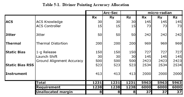
Table 2. DLRE pointing accuracy allocation. Table 5-1 from LRO Pointing and Alignment Spec GSFC 431-SPEC-000113.
16.0295º Theodolite

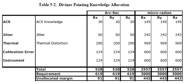
Table 3. DLRE pointing knowledge allocation. Table 5-2 from LRO Pointing and Alignment Spec GSFC 431-SPEC-000113.
IV. Nominal Configuration
Figure 1 shows schematically the DLRE instrument in its stowed position with relevant axes and vectors. The alignment cube is fixed to the base, so cannot rotate with respect to the spacecraft axes. Nominally the azimuth axis is parallel to the spacecraft Z axis, the elevation axis is perpendicular to the azimuth axis and, when the instrument is stowed, is parallel to the cube face 2 normal vector. The cube face 1 normal vector is perpendicular to both the azimuth axis and to cube face 2. Table 4 lists the nominal unit vectors with respect to the spacecraft axes.
Alignment Cube Solar Target


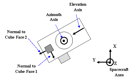
Figure 1. Schematic of DLRE instrument in its stowed position, showing relevant vectors and axes. The azimuth axis and the spacecraft Z axis point up out of the page.
|
Spacecraft Axis |
Azimuth Rotation Axis |
Elevation Rotation Axis (Stowed Position) |
|
|
|
X |
0 |
-sin(30º) = -0.5 |
-cos(30º) = -0.8660 |
-sin(30º) = -0.5 |
|
Y |
0 |
cos(30º) = 0.8660 |
-sin(30º) = -0.5 |
cos(30º) = 0.8660 |
|
Z |
1 |
0 |
0 |
0 |
Table 4. Nominal unit vectors relative to the spacecraft axes.
V. Laser Tracker Measurements of Rotation Axes and Solar Calibration Target
A laser tracker was used to measure the two rotation axes and the normal to the solar calibration target surface, all with respect to the alignment cube. The cube face unit normal vectors were determined as shown in Figure 2. Targets were positioned such that the laser tracker could see the target reflected in the cube face as well as directly. By determining the two vectors to each target, the reflecting cube face orientation could be determined.
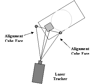
Figure 2. Laser tracker measurement of cube face normal vectors.
The rotation axes were determined by placing a target in an appropriate spot on the DLRE structure and rotating DLRE about the relevant axis. The elevation axis was measured when the azimuth axis was in stowed position (0º, azimuth actuator step 1000). The normal vector to the solar calibration target plane was determined by touching a target to each of the four corners of the solar calibration target top surface and measuring the target location in each case. The relative unit normal vectors thus determined are given in Table 5.
|
Axis |
Azimuth Rotation Axis |
Elevation Rotation Axis |
|
|
|
|
I |
0.00242161 |
-0.00276607 |
-1.00000000 |
-0.00020120 |
-0.25401060 |
|
J |
-0.01630531 |
0.99986960 |
0.00000146 |
0.99999998 |
-0.02245508 |
|
K |
0.99986413 |
0.01590982 |
0.00000052 |
0.00000002 |
0.96694073 |
Table 5. Relative unit vectors determined by laser tracker measurements.
After alignment to the LRO spacecraft, we will want all alignment measurements to be described in terms of the spacecraft axes. In this preliminary analysis, we will rotate the frame of reference such that the azimuth axis is pointed along +Z and the elevation axis is pointed, to the greatest extent possible, in the X-Y plane and rotated 30º from +Y towards the –X axis. This rotation can be obtained by multiplying the original unit vectors by the rotation matrix:

Multiplication by this rotation matrix results in the unit vectors given in Table 6.
|
Axis |
Azimuth
Rotation Axis |
Elevation
Rotation Axis |
|
|
|
|
I´ |
0.00000000 |
-0.49999996 |
-0.86740283 |
-0.49767755 |
-0.21903403 |
|
J´ |
0.00000000 |
0.86602533 |
-0.49760071 |
0.86720884 |
-0.13336091 |
|
K´ |
1.00000000 |
-0.00040222 |
-0.00242111 |
-0.01630578 |
0.96656037 |
Table 6. Laser tracker unit vectors after rotation.
VI. Theodolite Measurement From Alignment Cube to Target Projector Slit
Figure 3 shows the geometry for the theodolite measurements. Three theodolite positions were used. A Porro prism, fixed in position throughout the measurements, provided a reference angle. Table 7 lists all theodolite measurements. With the theodolite in position A, cube face 1 and the Porro prism were measured. With the theodolite in position B, cube face 2 and the Porro prism were measured. With the theodolite in position C, the target projector slits and the Porro prism were measured. The slit angular positions ere determined by looking into the collimated beam from the target projector. A flashlight illuminated the slits to make them visible through the theodolite.
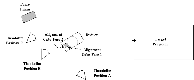
Figure 3. Schematic diagram of alignment setup, showing positions of the DLRE alignment cube, the target projector target, the Porro prism, and the three theodolite positions.
|
Measurement
Number |
Measurement |
Theodolite
Position |
Azimuth
Angle (º) |
Elevation
Angle (º) |
|
1 |
Cube Face 1 |
A |
10.0001 10.0004 10.0003 10.0008 9.9999 |
90.2328 90.2328 90.2324 90.2336 90.2324 |
|
2 |
Porro Prism |
A |
353.9708 353.9708 353.9709 353.9707 353.9710 |
|
|
3 |
Cube Face 2 |
B |
10.0000 10.0020 10.0015 10.0009 10.0006 |
90.6231 90.6226 90.6233 90.6231 90.6232 |
|
4 |
Porro Prism |
B |
263.9701 263.9702 263.9705 263.9704 263.9698 |
|
|
5 |
Vertical Slit in Target Projector, Instrument Removed |
C |
336.0800 |
|
|
6 |
Porro Prism |
C |
214.7043 214.7041 214.7045 214.7042 214.7044 |
|
|
7 |
Vertical Slit in Target Projector, Instument
Removed |
C |
336.0795 |
|
|
8 |
Horizontal Slit, Reposition slit
between measurements |
C |
|
88.7281 88.7160 |
|
9 |
Vertical Slit, Reposition slit between
measurements |
C |
336.0450 336.0864 |
|
Table 7. Summary of theodolite measurements.
The theodolite specified accuracy is 0.5 arcsec. Mark Thompson, the metrologist who made the measurements, feels that a more practical number for accuracy is 2 arcsec. The measurement with the most scatter (cube face 2) has a scatter of 0.002 degrees or 7 arcsec. It seems reasonable, therefore, to conclude that the accuracy of these measurements is at least better than ±10 arcsec (±0.003º, ±0.05 mrad.
The target projector slits are in a stepper-motor controlled wheel. It was found that the slit wheel did not always stop at the same position for a given slit. Between the various measurements of each slit, the slit was repositioned by rotating the slit wheel at least on revolution. The extremes of the slit positions were found and included in these measurements. The slit position was taken as the midpoint of these extreme measured values. Thus, from theodolite position C the slit center is 336.066±0.021º in azimuth and 88.722±0.006º in elevation.
Measurements 1 and 2 give an azimuth angle between cube face 1 and the Porro prism of 16.0295º (Figure 4). Measurement 1 shows that cube face 1 has an angle of 89.8600 with respect to gravity.
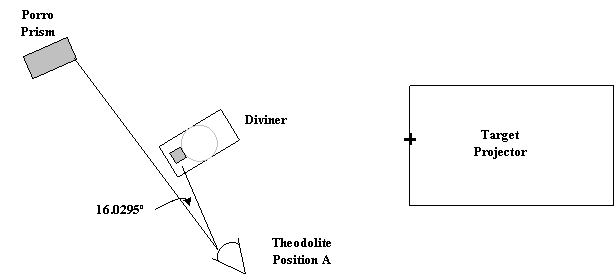
Figure 4. Relationship between cube face 1 and the Porro prism.
Measurements 3 and 4 give an azimuth angle between cube face 2 and the Porro prism of 106.0308º (Figure 5). Measurement 3 shows that cube face 2 has an angle with respect to gravity of 90.6231º.
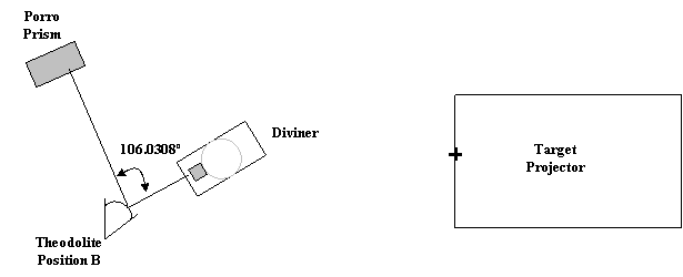
Figure 5. Relationship between cube face 2 and the Porro prism.
The measured azimuth angle between cube faces 1 and 2 is therefore 106.0308º-16.0295º = 90.0013º.
Measurements 5, 6, 7, and 9 give an azimuth angle between the target projector slit and the Porro prism of 121.368º (Figure 6).
Theodolite

Figure 6. Relationship between the target projector slit and the Porro prism.
Measurement 8 gives an angle between the target projector slit and gravity of 88.722º. A summary of the theodolite results is given in Table 8.
|
Angle |
Azimuth Angle (º) |
Elevation Angle (º) |
|
Cube Face
1 to Porro Prism |
16.0295±0.003 |
|
|
Cube Face
2 to Porro Prism |
106.0308±0.003 |
|
|
Target
Projector Slit to Porro Prism |
121.368±0.021 |
|
|
Cube Face
1 to Gravity |
|
89.860±0.003 |
|
Cube Face
2 to Gravity |
|
90.623±0.003 |
|
Target
Projector Slit to Gravity |
|
88.722±0.006 |
Table 8. Summary of theodolite measurements.
We arbitrarily define a zero azimuth angle as 46º from the Porro prism, with positive angle counterclockwise in the figures. This puts the zero in azimuth roughly parallel to the spacecraft X axis. The zero in elevation angle is set to 90º from the gravity vector, with positive angles upward. The resulting angles are summarized in Table 9.
|
Angle |
Azimuth Angle (º) |
Elevation Angle (º) |
|
|
209.9705 |
0.2328 |
|
|
119.9692 |
0.6231 |
|
Target
Projector Slit |
284.632 |
-1.278 |
Table 9. Summary of theodolite measurements.
A set of unit vectors summarizing the theodolite measurements is shown in Table 10.
|
Axis |
Cube
Face 1 |
Cube
Face 2 |
Target
Projector Slit |
|
i |
-0.86627557 |
-0.49950485 |
0.25254695 |
|
j |
-0.49954992 |
0.86624283 |
-0.96732755 |
|
k |
0.00406312 |
0.01087493 |
-0.02230346 |
Table 10. Unrotated unit vectors.
To put these vectors in the same frame of reference as the laser tracker measurements, they can be multiplied by the rotation matrix:

The resulting unit vectors deduced from the theodolite measurements are listed in Table 11.
|
Axis |
Cube
Face 1 |
Cube
Face 2 |
Target
Projector Slit |
|
i´ |
-0.86737252 |
-0.49757257 |
0.25064108 |
|
j´ |
-0.49765347 |
0.86726836 |
-0.96807752 |
|
k´ |
-0.0024373030 |
-0.01634425 |
0.00222731 |
Table 11. Rotated unit vectors determined from theodolite measurements.
As a partial check of the measurements and axes rotations, the cube face unit vectors can be compared. The angle between two unit vectors is the arccosine of the dot product of any two vectors. The laser tracker data from Table 6 indicates that the two cube faces differ from a 90º separation by 200 μrad. The theodolite data from Table 11 indicates that the two cube faces differ from a 90º separation by 21 μrad. These results give some indication of the accuracy of the two types of measurements - ±100 μrad for the laser tracker and ±10 μrad for the theodolite.
After rotation, the two cube face 1 vectors, measured with the laser tracker and the theodolite, are 63 μrad apart. After rotation the two cube face 2 vectors are 125 μrad apart. Thus the rotations used aligned the measurement to within the laser tracker accuracy.
VII. Errors in Alignment Knowledge within the DLRE Instrument
Table 12 lists values for the primary alignment error sources within the DLRE instrument.
|
Error
Source |
Error (º) |
Error (arc-sec) |
Error (mrad) |
|
Accuracy of alignment measurements
(largest inconsistency is orthogonality of cube faces in laser tracker
measurement). |
0.006 |
41 |
0.10 |
|
Uncertainty in position of target
projector slit |
0.021 |
70 |
0.37 |
|
Accuracy and repeatability of azimuth
actuator position (from DLRE Actuator
Verification Summary JPL D-41559) |
0.020 |
70 |
0.35 |
|
Accuracy and repeatability of
elevation actuator position (from DLRE
Actuator Verification Summary JPL D-41559) |
0.020 |
70 |
0.35 |
|
Total error due to actuators (rms of
previous two rows, since errors are orthogonal) |
0.028 |
99 |
0.49 |
|
Error due to pixel IFOV determination
(from DLRE FOV Test Report JPL D-42956
Section X, excluding actuator portion to avoid double counting of this error) |
0.040 |
144 |
0.7 |
|
Sum of errors |
0.095 |
354 |
1.7 |
|
RMS of errors |
0.054 |
194 |
0.94 |
Table 12. Errors in alignment knowledge.
VIII. Errors in Alignment Knowledge After In-Flight Calibration
During the commissioning phase of the mission, scans of the lunar horizon and comparison to LROC and LOLA data will be used as a calibration of DLRE alignment. The final DLRE alignment knowledge and accuracy will be limited by the accuracy of this calibration, of variations in DLRE’s alignment with the spacecraft (spacecraft thermal distortion, jitter, etc.), and DLRE’s internal variations in alignment. Careful in-flight calibration should provide better than ±1/10 pixel (±0.6 mrad) accuracy at the time of calibration. This calibration will remove many of the sources of error listed in Table 12, such as uncertainty in the slit position during FOV measurements and some of the uncertainty in IFOV determinations. This calibration will also remove any additional FOV shifts during launch. Contributions to DLRE’s internal alignment variation are listed in Table 13.
|
Error
Source |
|
Error (mrad) |
|
Accuracy and repeatability of azimuth
actuator position (from DLRE Actuator
Verification Summary JPL D-41559) |
|
0.35 |
|
Accuracy and repeatability of
elevation actuator position (from DLRE
Actuator Verification Summary JPL D-41559) |
|
0.35 |
|
Total error due to actuators (rms of
previous two rows, since errors are orthogonal) |
|
0.49 |
|
Temperature
dependence of IFOVs with respect to base of instrument (see DLRE FOV Test
Report, JPL D-42956, Section IX). |
|
0.53 |
|
RMS of errors |
|
0.72 |
Table 13. Contributions to DLRE’s internal alignment variation.
IX. Verification of Alignment Requirements
DLRE-MISC-NEW: Diviner shall stay within its pointing accuracy allocation as stated in Table 5-1 of the LRO Pointing and Alignment Spec (431-SPEC-000113).
Table 12 shows that the uncertainty in pointing accuracy is no worse than 1.7 mrad, compared to the 2.0 mrad shown in Table 2 (Table 5-1 of the LRO Pointing and Alignment Spec (431-SPEC-000113)).
DLRE-MISC-NEW: Diviner shall stay within its pointing knowledge allocation as stated in Table 5-2 of the LRO Pointing and Alignment Spec (431-SPEC-000113).
DLRE-MISC-NEW: Diviner shall stay within its pointing calibration allocation as stated in Table 5-2 of the LRO Pointing and Alignment Spec (431-SPEC-000113).
After alignment to spacecraft, Diviner’s pointing knowledge (1700 μrad per Table 12) will exceed the requirement (600 μrad per Table 3). In-flight calibration, however, will almost bring the alignment knowledge (720 μrad per Table 13) in line with the requirement. This smaller excedence consumes about 1/3 of the unallocated margin in Table 3. Thus, if the spacecraft doesn’t exceed its allocation significantly, the overall alignment knowledge after in-flight calibration will be within specifications.
DLRE-FRD-63a: The
orientation of the azimuth axis relative to the alignment cube shall be
measured to an accuracy of ±0.1 mrad.
DLRE-FRD-63b: The
orientation of the elevation axis relative to the alignment cube shall be
measured to an accuracy of ±0.1 mrad.
The axes’ orientations relative to the alignment cube were measured with the laser tracker. Laser tracker measurements of the two cube faces suggest an accuracy of about ±0.1 mrad.
DLRE-FRD-63c: For a single orientation in azimuth and a nominally 90º orientation in elevation, alignment of the boresight of telescope A relative to the alignment cube shall be measured to better than ±0.6mrad.
The field-of-view measurements represent a small range of azimuth positions and an elevation position of roughly 90º. Table 12 lists the uncertainty in pointing of a single pixel of 1.7 mrad. The boresight is determined somewhat better than this as it is an average of all pixels in each focal plane. After in-flight calibration, this error decreases to 0.72 mrad or less per Table 13. As stated above, this pointing knowledge will allow Diviner’s higher-level pointing requirements to be met.
DLRE-FRD-63d: For a
single orientation in azimuth and a nominally 90º orientation in elevation,
alignment of the array axes relative to the instrument axes shall be measured
to better than ±6mrad. The axis of an
array is defined by the best fit line through the peaks of all the detectors in
that array.
Figure 12 of the DLRE FOV Test Report JPL D-42956 shows all the pixel positions in azimuth and elevation steps. This data is taken from the low-resolution field-of-view measurements. Each single measurement is accurate to 1.7 mrad (0.96 actuator steps) in each axis (Table 12). Each data point represents an average of about four single measurements, and there are 21 data points for each channel. The linear fits shown in this Figure have an uncertainty in y value (azimuth position) of about 1.7 mrad /(4*21) = 0.2 mrad, and an uncertainty in slope of about 0.2 mrad/15 = 13 μrad (15 is roughly the rms value of elevation position about its mean). Thus the slopes are determined to much better than the required ±6mrad.
DLRE-FRD-240: The
plane of the solar calibration target shall be inclined 15°above the spacecraft
XY plane.
Once mounted on the spacecraft, the azimuth axis will be nearly parallel to the spacecraft Z axis (can be controlled to 6 mrad or 0.34º per Table 2). The angle of the solar calibration target above the spacecraft XY plane is the same as the angle between the solar calibration target normal and the spacecraft Z axis. This angle can be calculated by taking the arccosine of the dot product of the solar calibration target unit normal vector and the azimuth unit normal vector. Using values from Table 5 gives an angle of 14.86º.