This Software Interface
Specification (SIS) describes
the archived Lunar Reconnaissance Orbiter (LRO) Mini-RF instrument
science-related data products. Mini-RF is an instrument that flies on the NASA
LRO spacecraft. It is a synthetic aperture radar (SAR), which will image and
characterize the lunar surface. The Payload Operations Center (POC) is located
at the Johns Hopkins University Applied Physics Laboratory (APL) in Laurel,
Maryland. It hosts processing systems, which will generate levels of science
data products from the raw telemetry received from the instrument. The raw SAR
data are processed within the POC through Level 2 using Microsoft®/Vexcel®’s
SAR Processor. This document specifies the format and content of those
products and is intended to serve as a guide for producing and using them.
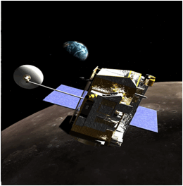
Figure 1:
The LRO spacecraft.
This document is intended for
scientists and engineers in the planetary science community and others who wish
to understand the format and content of the Mini-RF science data products. The
SIS applies to the Mini-RF data products produced during the course of LRO
Mission operations.
The LRO Mini-RF SIS references or is applicable to the
following documents:
1
Planetary Data System Standards Reference, NASA/JPL, February 27, 2009, Version 3.8.
JPL D-7669, Part-2. Available from http://pds.jpl.nasa.gov/documents/sr/index.html.
[Accessed: January 26, 2010].
2
Planetary Data System Archive Preparation Guide, August 29, 2006, Version 1.1, JPL D-31224,
NASA/JPL. Available from http://pds.jpl.nasa.gov/documents/apg/index.html.
[Accessed: May 8, 2007].
3
Lunar Reconnaissance Orbiter (LRO) Project Instrument Team Data
Management and Archive Plan,
Mini-RF program.
4
Lunar Reconnaissance Orbiter (LRO) Mini-RF Science Team and PDS
Geosciences Node Interface Control Document (ICD), Mini-RF program.
5
Data Interface Control Document for Mini-RF Advanced Technologies –
LRO (MRF-2101), Mini-RF
program.
6
Archive Volume Software Interface Specification (SIS) for Mini-RF
Advanced Technologies (LRO)
(MRF-4011), Mini-RF program [DOCUMENT/AV_SIS/MRFLRO_AV_SIS].
7
Lunar Reconnaissance Orbiter
Data Management and Archive Plan, 431-PLAN-000182, NASA/GSFC LRO Project.
8
P. L. McKerracher, J. R. Jensen, H. B. Sequeira, R. K. Raney, R.
C. Schulze, D. B. J. Bussey, B. J. Butler, C. D. Neish, M. Palsetia, G. W.
Patterson, P. D. Spudis, B. J. Thomson, F. S. Turner, Mini-RF calibration, a unique approach to on-orbit synthetic aperture
radar system calibration, 2010 [DOCUMENT/MRF_CAL/MRF_CAL_MCKERRACHER_ET_AL2010].
9
J. R. Jensen, LRO Mini-RF S-band transmit polarization
ellipse as observed at Green Bank on August 23, 2009 [DOCUMENT/GB_CAL/MRFLRO_CAL_GBT_JENSEN2010].
The LRO data products are
produced at the POC and are delivered to the PDS.
The products are decompressed radar image files, calibration data,
miscellaneous ancillary data, and possibly SPICE kernels. Their formats comply with PDS standards. The image and other files will
be archived to the PDS Geosciences node. Any SPICE kernels will be archived at
the PDS NAIF node.
Mini-RF is an instrument on the
LRO spacecraft. It is capable of active burst and continuous mode SAR imaging.
The continuous mode images are used to create interferometry (also called
“InSAR”) products. High-resolution SAR images of Polar Regions of the lunar
surface will be obtained. The search for water ice, particularly in the polar
regions of the Moon, is its primary science mission, but it will also
characterize the surface roughness and thickness of the regolith.
The LRO Mini-RF instrument has the following parameters,
which describe it. The associated values given here are typical, not absolute,
and many of them vary.
|
Parameter
|
S-Band
|
X-Band
|
|
Altitude
|
50 km (± 20)
|
|
Inclination
|
~90° (1.5° wobble, 14-day
period)
|
|
Incidence
|
~49°
|
|
Frequency
|
2.38 GHz (12.6 cm)
|
7.14 GHz (4.2 cm)
|
|
Polarization
|
Transmit RCP or LCP,
Receive coherent Horizontal & Vertical
|
|
Polarization
Purity
|
Cross-talk: 19 dB, axial
ratio: 1.7 dB (end-to-end)
|
|
Spacecraft
Velocity
|
1645 – 1665 m/s
|
|
SAR
Swath Width
|
6
km (baseline)
|
4
km
|
|
Strip
length
|
<400
km
|
|
Antenna
Length
|
1.8 m
|
|
Interferometry
Swath Width
|
3.5 km
|
|
Interferometry
Resolution
|
15 m/pixel
|
|
Antenna
Width
|
0.6 m
|
|
Beam
Width
|
3.6°
× 10.8°
|
1.2°
× 3.6°
|
|
Bore-sight
Gain (Two-way)
|
>
50.6 dB
|
>
57.5 dB
|
|
Noise
Equivalent Sigma Naught (Baseline)
|
-30 dB
|
|
|
Noise
Equivalent Sigma Naught (Zoom)
|
-25
dB
|
|
|
Slant
Range Resolution
|
115 m baseline, 23 m zoom
|
|
Ground
Range Resolution
|
150 m baseline, 15 × 30
zoom
|
|
Looks
|
16 baseline, 8 zoom
|
|
Azimuth
Resolution
|
150 m baseline, 15 × 30
zoom
|
|
Multiplicative
Noise Ratio
|
-12 dB
|
|
Transmit
Pulse Width
|
50 – 160 ms
|
|
Chirp
Bandwidth
|
1.6 MHz baseline, 8 MHz
zoom
|
|
Peak
Power at Transmitter Port
|
20 W
|
|
Average
Transmitted Power
|
6.4 – 8 W
|
|
PRF
|
2800 – 5000 Hz
|
|
No
samples/pulse
|
190 – 340 baseline,
1100 – 2000 zoom
|
|
A/D
Sampling Frequency
|
100 Mega-samples per pulse
(MSPS)
|
|
Number
of A/D Bits Per Sample
|
12
|
|
Number
of Received Channels
|
2
|
|
Collect
Time/Orbit
|
< 4 minutes
|
|
|
|
|
Table 1 Description
of the LRO Mini-RF instrument.
4.2 Data
Processing
There are two modes of data
acquisition from the Mini-RF instrument on the LRO spacecraft, burst and
continuous mode. Burst mode is referred to in this document as the standard
SAR product. Continuous mode (also a type of SAR product) is used to create
interferometry products. Processed numeric data products are provided in little-endian
format.
There are four levels of SAR data
products archived at the PDS: raw, Level 1, Level 2, and Level 3 (mosaics).
There is a Level 0 processing performed at the POC; however, these are
intermediate products that are not scientifically useful and are not archived
at the PDS. Additionally, there are ground calibration and ancillary products.
All are generated at the POC. Each product will have a unique file name and
follow the file naming convention (see File
Naming section 4.7.1).
Each product file will be associated with a particular data set (see Table 3). A special product, a refined
interferometry product, may also be produced. These are described in Appendix
section 6.1. The processing levels given in the DATA_SET_IDs are CODMAC
levels. All other references to processing levels in this document are NASA
processing levels.
|
NASA
|
CODMAC
|
Description
|
|
Packet data
|
Raw – Level 1
|
Telemetry data stream as received at the ground station,
with science and engineering data embedded.
|
|
Level-0
|
Edited – Level 2
|
Instrument science data (e.g., raw voltages, counts) at
full resolution, time ordered, with duplicates and transmission errors
removed.
|
|
Level 1-A
|
Calibrated – Level 3
|
Level 0 data that have been located in space and may have
been transformed (e.g., calibrated, rearranged) in a reversible manner and
packaged with needed ancillary and auxiliary data (e.g., radiances with the
calibration equations applied).
|
|
Level 1-B
|
Resampled – Level 4
|
Irreversibly transformed (e.g., resampled, remapped,
calibrated) values of the instrument measurements (e.g., radiances, magnetic
field strength).
|
|
Level 1C
|
Derived – Level 5
|
Level 1A or 1B data that have been resampled and mapped
onto uniform space-time grids. The data are calibrated (i.e., radiometrically
corrected) and may have additional corrections applied (e.g., terrain
correction).
|
|
Level 2
|
Derived – Level 5
|
Geophysical parameters, generally derived from Level 1
data, and located in space and time commensurate with instrument location,
pointing, and sampling.
|
|
Level 3
|
Derived – Level 5
|
Geophysical parameters mapped onto uniform space-time
grids.
|
|
|
Ancillary data – Level 6
|
Non-science data needed to generate calibrated
or resampled data sets. Consists of instrument gains, offsets; pointing
information for scan platforms, etc.
|
Table 2 The standard NASA and CODMAC processing levels for science data
sets. These are used in defining the data set IDs.
|
Product Type
|
Data Set ID
DATA_SET_NAME
|
POC
Processing Level
|
CODMAC Level
|
|
Packetized Data Records (PDR)
|
LRO-L-MRFLRO-1-PDR-V1.0
“LRO MOON MINI-RF 1 PACKETIZED DATA RECORD V1.0”
|
Raw
|
1
|
|
Calibrated Data Records (CDR)
|
LRO-L-MRFLRO-4-CDR-V1.0
“LRO MOON MINI-RF 4 CALIBRATED DATA RECORD V1.0”
|
1
|
4
|
|
Interferometric Calibrated Data Records
|
LRO-L-MRFLRO-4-CDR-INSAR-V1.0
“LRO MOON MINI-RF 4 INSAR CALIBRATED DATA REC V1.0”
|
1
|
4
|
|
Map-Projected Calibrated Data Records (CDR)
|
LRO-L-MRFLRO-5-CDR-MAP-V1.0
“LRO MOON MINI-RF 5 MAP-PROJECTED CALIBRATED DATA REC
V1.0”
|
2
|
5
|
|
Polar Mosaics
|
LRO-L-MRFLRO-5-CDR-MOSAIC-V1.0
“LRO MOON MINI-RF 5 POLAR MOSAIC CALIBRATED DATA REC V1.0”
|
3
|
5
|
|
SAR Stereo
|
LRO-L-MRFLRO-5-CDR-STEREO-V1.0
“LRO MOON MINI-RF 5 SAR STEREO CALIBRATED DATA REC V1.0”
|
3
|
5
|
|
SPICE Kernels*
|
LRO-L-SPICE-6-V1.0
|
N/A
|
6
|
Table 3 The archived science data products, their PDS data set IDs and
corresponding processing levels. See the description of CODMAC levels in Table
2. *SPICE
kernels (optional for the Mini-RF instrument) are archived separately at the NAIF
PDS node (VOLUME_ID = LROSP_1000).
|
Keyword
|
Value
|
|
MISSION_NAME
|
"LUNAR RECONNAISSANCE
ORBITER”
|
|
MISSION_ID
|
LRO
|
|
INSTRUMENT_HOST_NAME
|
" LUNAR RECONNAISSANCE
ORBITER "
|
|
INSTRUMENT_HOST_ID
|
LRO
|
|
INSTRUMENT_NAME
|
“MINI-RF LRO”
|
|
INSTRUMENT_ID
|
MRFLRO
|
Table 4 Values of
mission and instrument identifying key words.
4.2.2
Calibration
McKerracher et al (2010) [See
Sec. 2, Ref. 8] and Jensen (2010) [See Sec. 2, Ref. 9] describe instrument and
data calibration that are applied to the CDRs in documents included in the DOCUMENT
directory of the PDS archive. The raw calibration data products are available
in the CALIB directory in the accompanying archive. See CALIB/CALINFO.TXT for a
listing and discussion of these product files.
There are three levels of SAR LRO
data products produced while the instrument is in burst mode, which are
archived at the PDS Level 1, Level 2, and Level 3 (mosaics). The data are
created in the cross-product format in either the baseline or zoom resolution
modes with the square pixel spacing aspect ratio. Additionally, there are
ground calibration and ancillary products. All are generated at the POC. Each
product will have a unique file name and follow the file naming convention
given in section 4.7.1.
The processed science data
products are provided in little-endian format (PC_REAL).
The processing of SAR data into imagery involves the
following 3 broad processes.
·
Level 0 Processing
·
Level 1 Processing
·
Level 2 Processing
·
Generation of Level 3
mosaics from data from multiple orbits
The Level 0 processing is an
intermediate step in the production of deliverable SAR products. The resulting
Level 0 products are not scientifically useful in themselves, so they are not archived. However, they
are mentioned here to aid in the understanding of the deliverable products.
The Level 0 Processing steps involve the following:
·
Telemetry Packets
Processing (typically CCSDS format)
·
Processing of
available on-board calibration and housekeeping data
·
Meta-data Extraction
(reading of relevant radar parameters from science data header, reading of
ephemeris/attitude/time correlation from relevant files)
·
Parameter Estimation
(Doppler centroid and rate estimation for the data strip, geo-location, range
and azimuth spectra, raw data histogram)
The level 1 Processing can be
carried out in Burst Mode or Continuous Mode depending on the whether the
instrument acquired the phase history data in the burst or continuous modes. The flow chart for the Burst Mode processor for data acquired in one
polarization only is show in Figure
2 below. The
processing consists of the following major steps:
- Range Compression
- Range FFT
- Compression Filter
- Range IFFT
- Azimuth Compression
- Azimuth FFT
- Range Migration Curvature Correction
- Slant Range to Ground Range Conversion
- Azimuth IFFT
- Chirp Transform SPECAN
- Radiometric Compensation
- Range radiometric compensation
- Azimuth radiometric compensation
- Multi-look Overlay

Figure 2 The burst mode processor.
The level 2 processing steps involve the following:
·
Generation of the
corners of the output Level 2 image in the chosen projection. The corners serve
to provide processing bounds for the image strip to be ortho-rectified.
·
Image Formation,
wherein the L1 image, and optionally an available DEM or GCP file(s) are used
to project the image into desired projection.
Continuous mode data acquisition
is intended for use in producing interferometric (InSAR) data products. There
are two levels of continuous mode products archived at the PDS, Level 1 and
possibly derived topographic data (Level 3+). There is a Level 0 processing
performed at the POC; however, these are intermediate products that are not
scientifically useful and are not archived at the PDS. There are no Level 2 continuous mode products. All are generated at
the POC. Each product will have a unique file name and follow the file naming
convention (File Naming, section 4.7.1).
The flow chart for data acquired
in continuous mode for a single polarization channel is shown in the Figure 3 below. The processing consists of the
following major steps:
- Range Compression
- Range FFT
- Compression Filter
- Range IFFT
- Azimuth Compression
- Azimuth FFT
- Range Migration Curvature Correction
- Azimuth IFFT
- Radiometric Compensation
- Range radiometric compensation
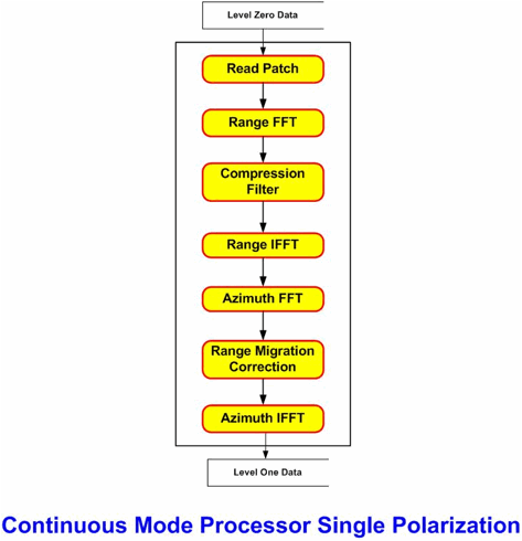
Figure 3 The continuous mode processor
The format and organization of
the archived science, calibration, and ancillary products are described in this
section. Metadata accompanies the Raw PDR and CDR data products in a Vexcel®-developed
human and machine-readable structured text format called “CONI.” These
metadata are stored in parameter files of the same name as the data product,
except that the file name suffix is .TXT.
The associated PDS label contains a reference to the parameter file. The
tables in this section contain detailed descriptions of the product files. The
Num Files column in
the tables indicates the number of files, which make up the specific product.
The Raw Packetized Data Records
(PDRs) are in the form of raw binary telemetry in Consultative Committee for
Space Data systems (CCSDS) packet format, which have been extracted from frames
downlinked from the instrument. PDRs have duplications removed and include any
ancillary information needed to understand what is in a given packet. They are
retained so that future researchers can reproduce the higher-level products if
they so desire. These data will not be reformatted or processed further and
are delivered to the PDS with detached minimal PDS labels. Because the
higher-level products can be reprocessed as often as desired, there may be a
one-to-many relationship a raw data product to a processed data product.
The formats of these packets are
identical, but their contents differ. Each of these packets is composed of
five segments: the CCSDS Primary Header which contains packet identification
information, the CCSDS Secondary Header which contains the packet time stamp,
the Science Header which contains associated metadata, the Science Data which
contains the data samples, and a trailer (“Other Data”) which contains
transmission information. Byte values are 8-bits long, Integer values are
32-bits long, short (integers) are 16-bits long, and floating point values are
32-bit IEEE numbers. These data only are provided in big-endian format.
The science data are time-ordered
and consist of Vertical (V) or Horizontal (H) polarization channel samples
contained within a pulse. The packets will contain either H or V channel data,
never both in the same packet. The “V/H Channel Indicator” flag in the Science
Header indicates if the data are H or V channel. Data gaps in the derived
products or breaks in the sequence count field in the primary CCSDS packet
header would indicate missing packets.
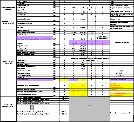
Table 5 Layouts of
the Raw Data PDRs. Unlike the other data products, the Raw PDR files are
delivered in big-endian format.
|
Product
|
File Type
|
Label Type
|
PDS Node
|
Num Files
|
File Name
Extension
|
Description
|
|
Packetized Data Records (PDR) [also referred to as raw
data]
|
CCSDS-formatted
binary
|
Minimal
|
Geosciences
|
1
|
DAT
|
Raw binary telemetry delivered by the LRO MOC consisting
of CCSDS packets with primary, secondary, and science headers. CCSDS packet
PDR data. Delivered with no supporting materials. One file for each pass.
Also called the “instrument telemetry CCSDS packets”. These packets contain
data from acquisitions in either continuous or burst mode.
|
|
Raw SAR Parameter File
|
TEXT
|
Shared with product label
|
Geosciences
|
1
|
TXT
|
The Raw data SAR Parameter File.
|
Table 6 Files
containing the Raw Data PDRs (DATASET_ID: LRO-L-MRFLRO-1-PDR-Vn.n).
Each pixel in the cross product burst contains like power
intensities (HH*, VV*) and the cross power intensity (HV*). The “H” and “V”
notation as used here is not to be confused with broadcast and receive
polarization.
The Level 1 data products are Level 1 Calibrated Data
Records (CDRs). The POC produces Level 1 SAR CDRs by ingesting the Level 0
EDRs and associated Level 0 ancillary files into the SAR processor (Level 0
data are intermediate products generated from raw (PDR) products. Level 0 data
are not archived in PDS.). The Level 1 CDRs are SAR images in range and
azimuth orientation with pixel values in beta naught, which have been
radiometrically and polarmetrically calibrated. Each cross-product image file
contains simple lines of pixels. Each pixel consists of four 4-byte floating-point
numbers for a total of 16 bytes. The first two floating-point numbers are the
image intensity values for the horizontal (H) and vertical (V) channel receive.
The second two numbers are the real and imaginary parts of the single complex
number, which gives the cross power intensity image between the H & V
receive. H & V represent the complex amplitudes of the horizontal and
vertically polarized backscatter respectively. An ‘*’ represents a complex
conjugate of H or V. The Level 1 products are the lowest level usable science
data products.
|
Product
|
File Type
|
Label Type
|
PDS Node
|
Num Files
|
File Name
Extension
|
Description
|
|
Level 1 Calibrated Data Record (CDR) SAR data.
|
Binary
|
Full
|
Geosciences
|
1
|
IMG
|
The ground range detected cross-product polarimetric image
file. Each pixel is represented by two 4-byte floating-point values and an
8-byte complex value (one 4-byte floating point real and one 4-byte floating
point imaginary value) for a total of 16 bytes per pixel. The first two
numbers are proportionate to HH* and VV* respectively. The next two numbers
are proportional to the real and imaginary parts respectively of HV*.
|
|
Level 1 SAR Parameter File
|
TEXT
|
Shared with product label
|
Geosciences
|
1
|
TXT
|
The Level 1 cross-product polarimetric SAR Parameter File.
|
Table 7 Level 1 files. IMG DAT files are binary
instrument data and TIF are TIFF images (DATASET_ID: LRO-L-MRFLRO-3-CDR-Vn.n).
The Level 2 burst mode data
products are CDRs that the POC produces by ingesting the Level 1 CDRs into the
Level 2 SAR processor. The Level 2 CDRs differ from the Level 1 products in
that they are orthorectified and are re-sampled into map projections. Typically,
images of regions between ±79° of the lunar equator will be rendered into
equirectangular projections. Images of regions closer to the lunar poles will
be rendered into oblique cylindrical projections. The “equator” of the map
projection will correspond to the line of longitude that the subspacecraft
point crossed at the equator before the data collection. These will be
archived both at the POC and at the PDS. Each pixel is of the same data type
as that of the Level 1 image. Seven derived products, sometimes referred to as
“daughter products” are included along with each Level 2 CDR. These daughter
products include four stokes parameter files, a circular polarization ratio
file, a same sense polarization ratio products, and an opposite sense
polarization ratio product.
4.3.2.2.1
Stokes Parameters
All Level 2 CDR image products
are each accompanied by four Stokes parameters files. Mini-RF transmits a right
circular polarized signal, and receives Horizontal and vertical polarized
signals, and the phase between the polarizations. The Level 2 file consists of
four pieces of information per pixel. The received power on the horizontal
polarization (ERH), the received power in the vertical polarization
(ERV) and the real and
imaginary portions of the cross product between the two polarization signals (Re ERH ERV*
& Im ERH ERV* ).
The
first Stokes parameter, defined as S1 = <|ELH|2 + |ELV|2>,
represents the total power or total intensity of the received field.
The
second Stokes parameter, defined as S2 = <|ELH|2 -
|ELV|2>,
represents the difference between the horizontally and vertical components of
the polarized portion of the received em field.
The third and fourth Stokes parameters are defined as S3 = 2 Re< ELH ELV*> and S4 = -2 Im < ELH ELV*>, respectively. They represent respectively
the cosine and the sine of the average phase between the horizontally and
vertically polarized components of the received field.
4.3.2.2.2
Polarization Products
4.3.2.2.2.1
Same sense circular polarization (SC)
Mini-RF
transmits two orthogonal, linearly polarized waves with a phase shift of
(nominally)one quarter of the wavelength, and the resulting superposition of
these two forms a (nominally) circularly polarized beam. The same sense
circular polarization product describes the polarization state of the received
field that has an identical polarization to the transmitted beam. This product
is calculated as one half of the difference between the Stokes S1 and S4 parameters (SC = 0.5*S1 – 0.5*S4).
4.3.2.2.2.2
Opposite sense circular polarization (OC)
The
opposite sense circular polarization product describes the polarization state
of the received field that has the opposite circular polarization to the transmitted beam. This product is
calculated as one half of the sum of the Stokes S1 and S4 parameters (OC
= 0.5*S1 + 0.5*S4).
4.3.2.2.2.3
Circular polarization ratio (CPR)
This dimensionless parameter is the ratio of
the same sense circular polarization to the opposite sense circular
polarization (CPR = SC / OC).
The average CPR value of the entire lunar surface is on the order of 0.3. CPR
values for certain types of surface deposits may be either anomalously low
(near zero for very smooth terrain) or anomalously high (>1.0 for blocky
large-scale rough features). High CPR also is due to volumetric backscattering
from thick deposits of frozen volatiles, such as water-ice.
Degree of polarization
(m): The fraction of radar
backscatter that is polarized is given by the ratio m = (S22
+ S32 + S42)1/2/S1. The average value of m at the moon is about 0.6.
|
Product
|
File Type
|
Label Type
|
PDS Node
|
Num Files
|
File Name
Extension
|
Description
|
|
Level 2 SAR Calibrated Data Record (CDR)
|
Binary
|
Full
|
Geosciences
|
1
|
IMG
|
Map-projected calibrated single swath CDR image data. One
file for north polar pass and another for the south polar pass. Each pixel
is represented by two 4-byte floating-point values and an 8-byte complex
value (one 4-byte floating point real and one 4-byte floating point imaginary
value) for a total of 16 bytes per pixel. The first two numbers are the intensity
images for H and V receive, respectively. The complex value is the cross
power intensity image between the H & V receive.
|
|
Level 2 SAR Parameter File
|
TEXT
|
Shared with product
|
Geosciences
|
1
|
TXT
|
The Level 2 SAR Parameter File.
|
|
Level 2 CDR SAR Stokes Parameters
|
Binary
|
Full
|
Geosciences
|
4
|
IMG
|
Map-projected calibrated single swath CDR image data. Stokes
parameters derived from the Level 2 SAR data. One file for each of the four
Stokes parameters. These files are used to produce the Level 3 mosaic
products. The stokes parameter values are double precision real numbers and
are dimensionless.
|
|
Level 2 CDR SAR Same-sense polarization image (SSP)
|
Binary
|
Full
|
Geosciences
|
1
|
IMG
|
Map-projected calibrated single swath CDR image data. Single–swath
CDR image data. Science product. One file for each pass. Data produced by
POC from Level 2 Stokes parameter files. These values are dimensionless.
|
|
Level 2 CDR SAR Opposite-sense polarization image (OSP)
|
Binary
|
Full
|
Geosciences
|
1
|
IMG
|
Map-projected calibrated single swath CDR image data. Single-swath
CDR image data. Science product. One file for each pass. Data produced by
POC from Level 2 Stokes parameter files. These values are dimensionless.
|
|
Level 2 CDR SAR Circular Polarization Ratio
|
Binary
|
Full
|
Geosciences
|
1
|
IMG
|
Map-projected calibrated single swath CDR image data. Single-swath
CDR image data. Science product. One file for each pass. Data produced by
POC from Level 2 Stokes parameter files. Ratio of same sense to opposite
sense polarization. These values are dimensionless.
|
|
CPR Quick Look Image
|
Image
|
Document
|
Geosciences
|
1
|
JPG
|
A reduced-size JPEG rendering of the circular polarization
ratio (CPR) image.
|
|
Stokes 1 Quick Look Image
|
Image
|
Document
|
Geosciences
|
1
|
JPG
|
A reduced-size JPEG rendering of the Stokes 1 parameters
image.
|
Table 8 Level 2 data
products (DATASET_ID: LRO-L-MRFLRO-3-CDR-MAP-Vn.n).
The Level 3 Burst mode data
products are Derived Data Records (DDRs) generated from multiple Level 2 CDRs.
They are mosaics that the POC produces by ingesting the Level 2 Stokes
parameter files into the ISIS software. Four Level 3 mosaics will be produced
of each lunar pole (i.e., regions above 80° latitude) per imaging opportunity.
Unlike the lower-level products, these are composed of data sets collected
during multiple acquisitions and are produced manually using the ISIS software
provided by the Astrogeology branch of the USGS. The final ISIS products are
archived at the PDS. Level 3 is the final stage of data processing performed
at the POC. These will be archived both at the POC and at the PDS.
|
LRO Product
|
File Type
|
Label Type
|
PDS Node
|
Num Files
|
File Name
Extension
|
Description
|
|
Level 3 SAR North Polar Mosaic
|
Binary
|
Full
|
Geosciences
|
8
|
IMG
|
North polar mosaic constructed from data acquired during
multiple orbits.
|
|
Level 3 SAR North Polar Mosaic Quick Look image
|
Image
|
Document
|
Geosciences
|
8
|
JPG
|
A JPEG rendering of the mosaic.
|
|
Level 3 SAR South Polar Mosaic
|
Binary
|
Full
|
Geosciences
|
8
|
IMG
|
South polar mosaic constructed from data acquired during
multiple orbits.
|
|
Level 3 SAR South Polar Mosaic Quick Look image
|
Image
|
Document
|
Geosciences
|
8
|
JPG
|
A TIFF rendering of the mosaic.
|
Table 9 Level 3 Burst
Mode SAR Mosaic data products produced using the USGS ISIS software
(DATASET_ID: LRO-L-MRFLRO-3-CDR-MOSAIC-Vn.n).
See Appendix sec. 6.1 for a
description of additional derived Level 3+ data products.
The continuous mode Level 1 data
products are Level 1 Calibrated Data Records (CDRs). These may be used to
create refined interferometric products. The POC produces Level 1 SAR CDRs by
ingesting the Level 0 EDRs and associated Level 0 ancillary files into the
Vexcel® SWATH processor. The Level 1 CDRs are SAR images and
interferometry in range and azimuth orientation with pixel values in beta
naught. The data are created in single-look complex format with pixel spacing
in the native sampling aspect ratios. They are the lowest level usable science
data products. There are no additional products produced from interferometry
data.
|
Product
|
File Type
|
Label Type
|
PDS Node
|
Num Files
|
File Name
Extension
|
Description
|
|
Level 1 CDR H Polarization Single Look Complex data
|
Binary
|
Full
|
Geosciences
|
1
|
IMG
|
Continuous mode Horizontal channel Interferometry image
strips. Each pixel is a complex number consisting of a 4-byte floating-point
real and 4-byte floating-point imaginary part for a total of 8-bytes.
|
|
Level 1 CDR H Polarization Single Look Complex Parameter
File
|
TEXT
|
Shared with product
|
Geosciences
|
1
|
TXT
|
Ancillary metadata listing the various parameters that
identify and describe the product.
|
|
Level 1 CDR V Polarization Single Look Complex data
|
Binary
|
Full
|
Geosciences
|
1
|
IMG
|
Continuous mode Vertical channel Interferometry image
strips. Each pixel is a complex number consisting of a 4-byte floating-point
real and 4-byte floating-point imaginary part for a total of 8-bytes.
|
|
Level 1 CDR V Polarization Single Look Complex Parameter
File
|
TEXT
|
Shared with product
|
Geosciences
|
1
|
TXT
|
Ancillary metadata listing the various parameters that
identify and describe the product. Produced in continuous acquisition mode
only.
|
Table 10 Level 1
files (DATASET_ID: LRO-L-MRFLRO-3-CDR-INSAR-Vn.n).
Calibration data products used in
processing consist of raw, packetized data records received from the Mini-RF
instrument on-board the spacecraft and produced by calibration activities using
the Arecibo Radio Telescope in Puerto Rico and the Greenbank Radio Telescope in
West Virginia. These are described in papers referenced in sec. 4.2.2.
|
Product
|
File Type
|
Label Type
|
PDS Node
|
Num Files
|
File Name
Extension
|
Description
|
|
Packetized Data Records (PDR) [also referred to as raw
data]
|
CCSDS-formatted
binary
|
Minimal
|
Geosciences
|
1
|
DAT
|
Raw binary telemetry delivered by the LRO MOC, the Arecibo
Radio Telescope, or the Greenbank Radio Telescope consisting of CCSDS packets
with primary, secondary, and science headers. CCSDS packet PDR data.
Delivered with no supporting materials.
|
|
Raw SAR Parameter File
|
TEXT
|
Shared with product label
|
Geosciences
|
1
|
TXT
|
The Raw data Parameter File.
|
|
Calibration Parameter
File
|
Text file
|
Minimal
|
Geosciences
|
1
|
TXT
|
File listing the various parameters and values used in
data calibration.
|
Table 11 Calibration
products. These products are found in the CALIB directory in the archive
volume.
4.3.6 Ancillary Data
Products
Ancillary data accompanies the science data and are also
archived at the POC and the PDS. They too will have detached PDS standard
labels.
The Instrument Housekeeping Data
contain information about the state of the instrument. The data are provided
in comma separated variable (CSV) text files. The exact contents of this may
vary depending on data rate and other factors. See Table 12 for a description of the ancillary data product
that contains these data.
The DEM files are produced using
both interferometric and SAR stereo techniques. They consist of
cartographically projected maps of topography. They will be used by scientists
to study the topography of the polar regions.
|
Product
|
File Type
|
Label Type
|
PDS Node
|
Num Files
|
File Name
Extension
|
Description
|
|
Digital Elevation Model (DEM) data file
|
Binary
|
Full
|
Geosciences
|
1
|
DAT
|
The Digital Elevation Model used in the SAR processors. A
description of these will be provided in a later version of this document.
|
|
Digital Elevation Model (DEM) parameter file
|
TEXT
|
Shared with product
|
Geosciences
|
1
|
TXT
|
The Digital Elevation Model parameter file.
|
|
Instrument Housekeeping Data
|
TEXT SPREAD-SHEET
|
Full
|
Geosciences
|
1
|
CSV
|
The instrument housekeeping (engineering) data.
|
Table 12 List of ancillary data files.
4.3.7 SPICE Kernels
The SPICE Kernels are structured
parameter files that describe, among other things, the ephemeris and attitude
of the spacecraft, the spatial orientation of the instrument, the ephemeris and
physical parameters of the Earth, Moon and other natural bodies in the Solar
System, the relationship between spacecraft time and time as measured on Earth,
and the locations and orientations of ground stations. Some of these files are
standard products generated by the NAIF team at JPL and are not mission
specific. Others are produced specifically for a particular mission or
instrument. Some of these files are binary and others are text. The SPICE
kernels generated for the overall LRO mission will not be part of the data
archive generated by the POC and delivered to the PDS. The LRO project will
manage these and provide for their archiving. If SPICE kernels are generated
specifically for the Mini-RF instrument, they will be archived separately at
the NAIF node of the PDS. These are optional products. The Mini-RF project
will determine during the course of the mission if any instrument-specific
SPICE kernels are to be created. There existence and archival at the NAIF node
will be noted in the AAREADME.TXT file that accompanies the archive volume.
SPICE Kernel files are intended
for use with the SPICE software library. This is a software product from the
Navigation and Ancillary Information Facility (NAIF) at the NASA Jet Propulsion
Laboratory (JPL), which contains functions that perform computations for space
mission-related and astronomical applications. Any SPICE kernels used in product generation will be listed
in the SOURCE_PRODUCT_ID field of the accompanying PDS labels.
|
Product
|
File Type
|
Label Type
|
PDS Node
|
Num Files
|
File Name Extension
|
Description
|
|
Instrument Kernel
|
SPICE IK Kernel
|
SPICE Kernel label
|
NAIF
|
1
|
ti
|
Instrument field of view kernel. This is an optional
product.
|
Table 13 SPICE kernels optionally delivered with the product sets.
4.3.8 PDS Archive
Files
There is a set of standard files that accompany a data
product to be archived at the PDS. These files and some supporting documents
are described here. See the Mini-RF LRO Data Archive Volume SIS [sec. 6] document
for more information about these files and their locations in the archive.
|
Product
|
File Type
|
Label Type
|
PDS Node
|
Num Files
|
File Name
Extension
|
Description
|
|
AAREADME.TXT
|
Plain Text
|
Document attached
|
Geosciences
|
1
|
TXT
|
Volume content and format information. Includes the
location of any instrument-specific SPICE kernels created.
|
|
ERRATA.TXT
|
Plain Text
|
Document attached
|
Geosciences
|
1
|
TXT
|
A cumulative listing of comments and updates relating to
the Forerunner science data archive.
|
|
VOLDESC.CAT
|
PVL Text
|
N/A
|
Geosciences
|
1
|
CAT
|
A description of the contents of the delivered product
set.
|
|
INDXINFO.TXT
|
Plain Text
|
Document attached
|
Geosciences
|
1
|
TXT
|
A description of the contents of the Index directory.
|
|
INDEX.TAB
|
Text Table
|
Full
|
Geosciences
|
1
|
TAB
|
A table listing all of the data products in the delivery.
|
|
MD5.TAB
|
Text Table
|
Full
|
Geosciences
|
1
|
TAB
|
Contains a cumulative set of MD5 checksum values for each
file in the archive.
|
|
DOCINFO.TXT
|
Plain Text
|
Document attached
|
Geosciences
|
1
|
TXT
|
A description of the contents of the Document directory.
|
|
MRFLRO_DP_SIS.PDF
|
Adobe PDF
|
Document
|
Geosciences
|
1
|
PDF
|
The Data Product SIS (this document) in PDF format. The
PDS label is shared with the HTML version below.
|
|
MRFLRO_DP_SIS.HTM, IMAGE*.GIF, IMAGE*.JPG
|
HTML Text
|
Document
|
Geosciences
|
8
|
HTM
|
This document in HTML format. Associated images will be
in JPEG and GIF files.
|
|
MRFLRO_AV_SIS.PDF
|
Adobe PDF
|
Document
|
Geosciences
|
1
|
PDF
|
The archive volume SIS document in PDF format. The PDS
label is shared with the HTML version below.
|
|
MRFLRO_AV_SIS.HTM, IMAGE*.GIF, IMAGE*.JPG
|
HTML Text
|
Document
|
Geosciences
|
1
|
HTM
|
The archive volume SIS document in HTML format. Associated
images will be in JPEG and GIF files.
|
|
MRF_CAL_MCKERRACHER_ET_AL2010.PDF
|
Adobe PDF
|
Document
|
Geosciences
|
1
|
PDF
|
Mini-RF Calibration white paper in PDF format. The PDS
label is shared with the HTML version below.
|
|
MRF_CAL_MCKERRACHER_ET_AL2010.HTM, IMAGE*.GIF or JPG
|
HTML Text
|
Document
|
Geosciences
|
1
|
HTM
|
Mini-RF Calibration white paper in HTML format. Associated
images will be in JPEG and/or GIF files.
|
|
MRFLRO_CAL_GBT_JENSEN2009.PDF
|
Adobe PDF
|
Document
|
Geosciences
|
1
|
PDF
|
Mini-RF Calibration white paper in PDF format. The PDS label
is shared with the HTML version below.
|
|
MRFLRO_CAL_GBT_JENSEN2009.HTM,
IMAGE*.GIF or JPG
|
HTML Text
|
Document
|
Geosciences
|
1
|
HTM
|
Mini-RF Calibration white paper in HTML format. Associated
images will be in JPEG and/or GIF files.
|
|
CATINFO.TXT
|
Plain Text
|
Document attached
|
Geosciences
|
1
|
TXT
|
A description of the contents of the Catalog directory.
|
|
*_DS.CAT
|
PVL Text
|
N/A
|
Geosciences
|
1
|
CAT
|
Data set information for the PDS catalog. These will have
the following file names:
MRFLRO_1_PDR_DS.CAT MRFLRO_4_CDR_DS.CAT
MRFLRO_4_CDR_INSAR_DS.CAT MRFLRO_5_CDR_MAP_DS.CAT MRLRO_5_CDR_MOSAIC_DS.CAT
|
|
INSTHOST.CAT
|
PVL Text
|
N/A
|
Geosciences
|
1
|
CAT
|
Information about the LRO spacecraft for the PDS catalog.
|
|
INST.CAT
|
PVL Text
|
N/A
|
Geosciences
|
1
|
CAT
|
Information about the Mini-RF instrument for the PDS
catalog.
|
|
MISSION.CAT
|
PVL Text
|
N/A
|
Geosciences
|
1
|
CAT
|
Information about the overall mission for the PDS catalog.
|
|
PERSON.CAT
|
PVL Text
|
N/A
|
Geosciences
|
1
|
CAT
|
Information about key personnel involved in the Forerunner
project for the PDS catalog.
|
|
REF.CAT
|
PVL Text
|
N/A
|
Geosciences
|
1
|
CAT
|
References mentioned in other *.CAT files.
|
|
CALINFO.TXT
|
Plain Text
|
Document attached
|
Geosciences
|
1
|
TXT
|
A description of the contents of the Calibration
directory. This directory contains the calibration files referenced in
section 4.2.2.
|
Table 14 PDS
standard files that contain descriptive and indexing information about the
archive.
4.4
Data Product Archiving
The LRO
Mini-RF POC is responsible for science data product generation, validation, and
archiving. The POC supports and works with the LRO mission operations, the LRO
Mini-RF science team, and the PDS.
Prior to science phase of the LRO
mission, the POC produces sample data products from raw telemetry generated by
spacecraft and instrument simulators located at GSFC. During the mission, the
spacecraft control center receives the science data downlink from the
spacecraft on one channel and the housekeeping data on a second channel. The
MOC sends the raw data from the Mini-RF instrument to the POC through a data
link. At the POC, the Vexcel® SAR and Calibration processors
process the raw SAR data through levels 0, 1, and 2. Level 3 mosaics are
produced using the ISIS software from the USGS. Interferometry data are
processed through a separate processor. Software applications developed
specifically for and running only at the POC facilitate this processing and
package the data for later archiving at the PDS.
The Vexcel® SAR
processors consist of the SKY Level 0 processor (products not archived), the
SWATH Level 1 processor, and the ORTHO Level 2 processor. Each processor’s
output products are the input to the next level’s processor. Calibration is
performed by the Vexcel® CALPRO processor.
4.4.2 Labeling and
Identification
With the exception of the Raw data, all data products described in this
document which are to be delivered to the PDS are accompanied by full PDS
standard labels. Detached minimal labels accompany the Raw data. The PDS
labels are detached text files, which describe the associated product file.
There will be one label file for each product file. These labels conform to
the PDS version 3 standards. A product ID in its PDS label will uniquely
identify each product. The file name may be used for the product ID as long as
it is unique.
The PDS label describes and provides ancillary information about the
data product. They are written in a structured text language called “Object
Description Language (ODL).” Examples of a LRO Mini-RF PDS labels are given
in section 4.8.2. Note that not all of the keywords are
necessarily present in a given PDS label.
The LRO Mini-RF science and
calibration data products are constructed according to the data object concepts developed by the
PDS. By adopting the PDS format, the data products are consistent in
content and organization with other planetary image collections. In the PDS
standard, the data product file is grouped into objects with PDS labels describing
the objects. All PDS labels are written in ODL, a subset of the Parameter
Value Language (PVL), which is a structured text format (Applicable Document
1). The LRO Mini-RF data products contain:
- PDS Label Files
describing the specific product (including external data files)
- SAR or Interferometry
image data files.
- Stokes parameter
files.
- Calibration data files.
- Ancillary files
containing housekeeping data, lunar geometric data, and metadata in an
ASCII table format.
- Documentation.
The image data will be delivered in an uncompressed form.
All time values in the PDS labels
shall be given in Coordinated Universal Time (UTC). The time in UTC shall be
represented in ISO calendar format standard: yyyy-mm-ddThh:mm:ss.ss eg 2006-08-14T15:02:10.12.
The spacecraft time in Mission
Elapsed Time (MET) shall also be given in the science product labels in the
form of SPICE spacecraft clock (SCLK) strings. An SCLK string has the form “<partition>/<MET seconds>:<MET
subseconds>”, where partition is the current spacecraft clock partition,
MET seconds is the mission elapsed
time in seconds, and MET subseconds
is the vernier counter representing a fraction of a second. An example of an
SCLK string is “1/123456789:123456”.
Table 11 lists the computational
assumptions for the geometric and viewing data provided in the PDS label. There
are two reference frames (coordinate systems) in use: 1) the International
Celestial Reference Frame (ICRF), also frequently called the J2000 or the E.M.E.
2000 frame, used for target and spacecraft position and velocity vectors, and
instrument pointing and 2) a lunar body-fixed reference frame, used for
specifying certain viewing geometry vectors and target location. The lunar
body-fixed frame used by the Mini-RF investigation is the Mean Earth/Polar Axis
frame (commonly abbreviated as ME), as realized using NASA’s SPICE products
(Frames Kernel).
|
Item
|
Assumption
|
Comment
|
|
Geometric Elements
|
The mid-point time of observation is used for the
geometric element computations.
|
|
|
Label Parameters
|
The label parameters reflect the observed, not the true
geometry. Therefore, light-time and stellar aberration corrections are used
as appropriate.
|
|
|
Inertial Reference Frame
|
The inertial reference frame is J2000 (also called
“EME2000”)
|
|
|
Coordinate System
|
Latitudes and longitudes are given in the Mean Earth/Polar
Axis (ME) coordinate system.
|
LRO project teams may optionally use the Principal Axis
(PA) coordinate system internally, but will always use the ME coordinate system
for data archived at the PDS.
|
|
Sub-Point
|
The “sub-point” of a body on a target is defined by the
surface intercept of the body-to-target-center vector. This is not the
closest point on the body to the observer. This definition gives sub-point
latitude and longitude that are independent of the reference ellipsoid.
|
|
|
Units
|
Distances are in km, speeds in km/sec, angles in degrees,
and angular rates in degrees/sec unless otherwise noted.
|
|
|
Angular Ranges
|
Angle ranges are 0 to 360 degrees for azimuths and local
hour angles. Longitudes range from 0 to 360 degrees (positive to the East).
Latitudes range from ‑90 to 90 degrees.
|
|
|
Geometric Parameters
|
SPICE kernel files are used to store the geometric
parameters.
|
|
Table 15 Computational assumptions.
4.5.4 Archiving
Standard
The science data products will be archived by orbit number
and the complete archive will consist of approximately 720 orbits.
All text files are of standard ASCII format and in
accordance with PDS standards, each line in a text file terminates with a
carriage return (ASCII 13) and line feed (ASCII 10) end of line (EOL) marker
(i.e., <CR><LF>).
Basic data validation is performed at the POC
and consists of the following:
- POC
staff check the data products for conformance to this document and the
Archive Volume SIS, and for valid science content.
- Generation
of data products and volumes, together with validation are completed
within the required validation period of six months from the availability
of processing input data.
- Prior
to the first delivery of the products to the PDS, PDS representatives and
other interested parties review a sample product set generated by the POC
and may request changes to the product set as necessary to conform to the
SIS.
- The
data pipeline is also reviewed as part of the validation process.
- In
accordance with PDS requirements, the design of the data products as
described by this Data Product SIS, and as shown by a set of sample
products, undergoes a peer review prior to the beginning of processing.
A review committee made up of a few scientists who are knowledgeable in
the area along with representatives from the POC and the PDS evaluate the
products. They may produce a list of liens against the product set that
will be resolved prior to PDS archiving.
The
file names developed for any PDS archive are restricted to a maximum 27-character base name and 2 or 3
character extension name with a period separating the file and extension
names. Also known as the “27.3” format, this is compliant with the ISO 9660
Level 2 specification, which is required by PDS. All file names for products
archived at the PDS contain only capital letters, numerals, and underscores
(except for the one period ‘.’ which separates the file basename from the file
extension). All files begin with the one character instrument identifier L (LRO) which is the file designation
for all LRO Mini-RF files. In accordance with PDS standards, all file names are
in capital letters. The three-character file extension for each type of
product file is given in the File Extension column of each product description
table in section 4.2.1.
The following table describes the
detailed naming convention used for the Raw, Level 1, Level 2, and Level 3 data
products. The Vexcel® processors produce the Level 1 and Level 2
products.
Format: Mfm_ooooo_ltt_abu_ccdeee
_Vv.ext
M =
Indicates the instrument.
L = LRO
F =
Forerunner
B = Both
f =
Frequency band
S = S-band
X = X-band
B = Both
N = N/A
m =
Radar mode
B = Baseline SAR
I = Interferometry
S = Scatterometry
Z = Zoom
A = Arecibo
Radio Telescope Calibration
G =
Greenbank Radio Telescope Calibration
C = Other
Calibration
O = Other
(housekeeping, etc.)
ooooo = The orbit number in which
the data acquisition began. Numeric, range 00001…99999.
l = Processing
level
R = Raw PDR
1 = Level 1
2 = Level 2
3 = Level 3
tt = File
type
PD = Packetized Data Records
CD = Calibrated Data Records
S1 = Stokes Parameter 1 File
S2 = Stokes Parameter 2 File
S3 = Stokes Parameter 3 File
S4 = Stokes Parameter 4 File
SC = Same-Sense Polarization Image File
OC = Opposite-Sense Polarization Image
File
CP = Circular Polarization Ratio image
File
HK
= Instrument Housekeeping data (Associated with
RAW
data only)
a = projection
O = Oblique cylindrical
E = Equirectangular
P = Polar
stereographic
X = N/A (for Raw, Level 1,
Housekeeping, cal, etc.)
b = pixel resolution bin scale in pixels per
degree (ppd)
A = 1 ppd
B = 2 ppd
C = 4 ppd
See Table
16.
X = N/A (calibration
or housekeeping data)
|
Designator
|
Pixels/Degree
(ppd)
|
Meters/Pixel (mpd)
|
|
A
|
1
|
30323
|
|
B
|
2
|
15162
|
|
C
|
4
|
7581
|
|
D
|
8
|
3790
|
|
E
|
16
|
1895
|
|
F
|
32
|
948
|
|
G
|
64
|
474
|
|
H
|
128
|
237
|
|
I
|
256
|
118
|
|
J
|
512
|
59
|
|
K
|
1024
|
29.6
|
|
L
|
2048
|
14.8
|
|
M
|
4096
|
7.4
|
|
N
|
8192
|
3.7
|
|
O
|
16384
|
1.9
|
|
X
|
N/A
|
N/A
|
Table 16
Association of letter-designated bins for pixel resolutions.
u = bit type and scaling
U = Unnormalized floating point
F = Normalized floating point
B = Byte
cc = Lunar center latitude to nearest whole
degree
Numeric
value range 00…90.
XX = N/A or Unknown
d = hemisphere of latitude
N = North latitude
S = South latitude
X = N/A
eee = Lunar center longitude to
nearest whole degree
Numeric
value range 000…359.
XXX = N/A or Unkown
IMG = Processed image file
DAT = Unformatted binary data (e.g.,
raw files)
JPG = JPEG formatted browse images
TXT = Unstructured text data (e.g.,
parameter
files)
CSV = Comma Separated Value text files
(housekeeping)
LBL = PDS label file
The following is an example file
name of a Mini-RF SAR mode raw data product. It is baseline SAR, S-band, raw
data, packetized data record, byte format, no projection, 75 m/pixel resolution,
center coordinates 82ºN, 231º, orbit 512, version 1.
LSB_00512_RPD_XJB_82N231_V1.DAT
The following is an example file
name of a Mini-RF LRO SAR mode level 2 CDR data product. It is zoom mode,
X-band, level 2 processed, calibrated data record, oblique cylindrical
projection, 512 pixels/degree resolution, unnormalized floating point format,
center coordinates 82ºN, 231º, orbit 617, version 3.
LXZ_00617_2CD_OJU_82N231_V3.IMG
The following is an example file
name of a Mini-RF LRO SAR mode level 2 stokes 3 data product. It is baseline
SAR mode, S-band, level 2 processed, stokes parameter, simple cylindrical
projection, unnormalized floating point format, 512 pixels/degree resolution,
center coordinates 82ºN, 231º, orbit 512, version 2.
LSB_00512_2S3_EJU_82N231_V2.IMG
The following is an example file name of a Mini-RF LRO
calibration data product. It is a raw product collected using the Arecibo Radio
Telescope. The spacecraft orbit number is 975, it is a raw packetized data
record product, bit type is binary, the location on the Moon is not specified,
and it is version 1.
LSA_00975_RPD_XXB_XXXXXX_V1.DAT
The following table describes the
detailed naming convention for this dataset. These products are mosaics. They
contain data from multiple orbits. The file names of the polar mosaics follow
the same naming convention as the other science products, except that the
center latitude and longitude given in their file names are that of the center
of the mosaic and the orbit number is that of the highest orbit number product among
the lower-level products used in the mosaic.
The following is an example file
name of a Mini-RF LRO polar mosaic, zoom, SAR, S-band, level 3, same-sense
polarization, unnormalized floating point, north pole mosaic product, 2048 ppd,
version 01. The highest orbit number data that was used was orbit 752.
LSZ_00752_3SC_PLU_90N000_V1.IMG
All files have a corresponding PDS label of the same name
except for a suffix ending .LBL.
4.7.1.3 File Naming
Conventions for SPICE Kernels
The Mini-RF instrument kernel is the only LRO kernel,
which might be created, by the POC and therefore, the only one discussed here.
The creation of this product is optional. The LRO project creates other SPICE
kernels for the mission, but they are created and archived separately and not
discussed here. The file naming convention for the sole Mini-RF SPICE kernels
is lro_mrf_vv.ti where nn is the version number and the “.ti”
suffix indicates that it is an instrument kernel. The kernel filename is in all
lower-case per PDS NAIF node standards.
Instrument kernel (IK):
Format:
lro_mrf_vnn.ti
Label: lro_mrf_vnn.lbl
4.7.1.4 File Naming
Conventions for the Digital Elevation Model (DEM) File
The DEM naming convention and
that of its associated parameter file are given below. yyyymmdd is the date that they were released. If provided, the DEM
files will be included in the EXTRAS directory within the archive volume and
will not have associated PDS labels.
Format: LUNAR_DEM_yyyymmdd_vv.DAT
Format : LUNAR_DEM_yyyymmdd_vv.TXT
4.8 Label
and Header Descriptions
The key words used in LRO Mini-RF data product PDS labels
are described in Table 17 below.
|
Key Word
|
Description
|
|
A_AXIS_RADIUS
|
The a_axis_radius element provides the value of the semimajor axis of the ellipsoid that defines the approximate shape of a target body. 'A' is usually in the equatorial plane. |
|
B_AXIS_RADIUS
|
The b_axis_radius element provides the value of the intermediate axis of the ellipsoid that defines the approximate shape of a target body. 'B' is usually in the equatorial plane. |
|
C_AXIS_RADIUS
|
The c_axis_radius element provides the value of the semiminor axis of the ellipsoid that defines the approximate shape of a target body. 'C' is normal to the plane defined by 'A' and 'B'. |
|
AZIMUTH_RESOLUTION
|
The radar image line resolution.
|
|
BANDS
|
The BANDS element indicates the number of bands in the image. |
|
BAND_NAME
|
BAND_NAME is the name given to a single band in a multi-band image or image qube. These identify the components of the radar image pixel. |
|
BAND_STORAGE_TYPE
|
The band_storage_type element indicates the storage sequence of lines, samples and bands in an image. The values describe, for example, how different samples are interleaved in image lines, or how samples from different bands are arranged sequentially. |
|
CENTER_FREQUENCY
|
The carrier frequency of the SAR in Hertz. |
|
CENTER_LATITUDE
|
The center_latitude element provides a reference latitude for the map projections (always 0 for oblique cylindrical) and a center point for Level 1 images. |
|
CENTER_LONGITUDE
|
The center longitude element provides a reference
longitude for the map projections (always 0 for oblique cylindrical) and a
center point for Level 1 images.
|
|
CHECKSUM
|
A CRC checksum value for the data file produced
by the Posix cksum utility.
|
|
COORDINATE_SYSTEM_NAME
|
The coordinate_system_name element provides the full name of the coordinate system to which the state vectors are referenced. |
|
COORDINATE_SYSTEM_TYPE
|
There are three basic types of coordinate systems: body-fixed rotating, body-fixed non-rotating and inertial. A body-fixed coordinate system is one associated with a body (e.g., the Moon). |
|
^DATA_SET_MAP_PROJECTION
|
Reference to the file that describes the oblique
cylindrical map projection.
|
|
DATA_SET_ID
|
Uniquely identifies the data sets available on
the volume. The EDR collection is made up of a single data set.
|
|
DATA_SET_NAME
|
The full name given to the data set. |
|
DESCRIPTION
|
A narrative description of an object described in
the label.
|
|
EASTERNMOST_LONGITUDE
|
The maximum numerical value of longitude unless it crosses the Prime Meridian. |
|
FIRST_STANDARD_PARALLEL
|
A required keyword; however, it is not applicable
for oblique cylindrical projects. Always “N/A”.
|
|
^IMAGE
|
The file name of the image data product being
described.
|
|
INCIDENCE_ANGLE
|
The sensor beam incidence angle. The angle between the local vertical and the spacecraft direction. |
|
INSTRUMENT_HOST_ID
|
The unique identifier for the spacecraft which carries the instrument. |
|
INSTRUMENT_HOST_NAME
|
The full name of the spacecraft which carries the
instrument.
|
|
INSTRUMENT_MODE_DESC
|
Describes the instrument mode which is identified by the instrument_mode_id element. |
|
INSTRUMENT_MODE_ID
|
The instrument-dependent designation of operating mode. |
|
INSTRUMENT_NAME
|
The FULL name of the instrument. Note that the
associated INSTRUMENT_ID element provides an abbreviated name or acronym for
the instrument.
|
|
INSTRUMENT_ID
|
Abbreviated name or acronym which identifies the
instrument.
|
|
KEYWORD_LATITUDE_TYPE
|
Identifies the type of latitude (planetocentric) used in the labels, e.g., for the maximum, minimum, center, reference, and standard-parallel latitudes. |
|
LINE_FIRST_PIXEL
|
The line index of the first pixel that was physically recorded at the beginning of the image array. |
|
LINE_LAST_PIXEL
|
The line index of the last pixel that was
physically recorded at the end of the image array.
|
|
LINE_PROJECTION_OFFSET
|
The line offset value of the map projection origin position from the line and sample 1,1 (line and sample 1,1 is considered the upper left corner of the digital array). |
|
LINES
|
The total number of data instances along the vertical axis of an image. |
|
LINE_SAMPLES
|
The total number of data instances along the
horizontal axis of an image.
|
|
FILE_NAME
|
The name of the product data file described by
the label.
|
|
FILE_RECORDS
|
The number of physical file records, including
both label records and data records.
|
|
LABEL_REVISION_NOTE
|
Indicates the revision date and authorship of the
current label.
|
|
LINE_EXPOSURE_DURATION
|
The time elapsed during the acquisition of one
image line of data.
|
|
LOOK_DIRECTION
|
The value (RIGHT or LEFT) indicates the side of
the spacecraft groundtrack to which the antenna is pointed for data acquired
within a synthetic aperture radar (SAR) image.
|
|
MAP_PROJECTION_ROTATION
|
The clockwise rotation, in degrees, of the line
and sample coordinates with respect to the map projection origin. Always 90
for oblique cylindrical projections.
|
|
MAP_PROJECTION_TYPE
|
Identifies the type of projection characteristic of a given map, always oblique cylindrical in this case. |
|
MAP_RESOLUTION
|
The scale of the map in pixels/degree. The scale is defined as the ratio of the actual distance between two points on the surface of the target body to the distance between the corresponding points on the map. |
|
MAP_SCALE
|
The scale of the map in kilometers/pixel. The
scale is defined as the ratio of the actual distance between two points on the
surface of the target body to the distance between the corresponding points
on the map.
|
|
MAXIMUM
|
Indicates the largest pixel value in the image.
|
|
MAXIMUM_LATITUDE
|
The northern most latitude represented in the
image.
|
|
MD5_CHECKSUM
|
A checksum value using the MD5 algorithm.
|
|
MEAN
|
The mean value of the pixels in the image.
|
|
MINIMUM
|
Indicates the smallest pixel value in the image.
|
|
MINIMUM_LATITUDE
|
The southern most latitude represented in the
image.
|
|
MISSION_NAME
|
Identifies the mission.
|
|
NAME
|
The common term used to describe the type of data
described in the label.
|
|
OBLIQUE_PROJ_POLE_LATITUDE
|
One of the three angles defining the oblique coordinate system used in the OBLIQUE CYLINDRICAL projection. This is the ordinary latitude in degrees of the pole (Z axis) of the oblique system. |
|
OBLIQUE_PROJ_POLE_LONGITUDE
|
One of the three angles defining the oblique coordinate system used in the OBLIQUE CYLINDRICAL projection. This is the ordinary longitude in degrees of the pole (Z axis) of the oblique system. |
|
OBLIQUE_PROJ_POLE_ROTATION
|
One of the three angles defining the oblique coordinate system used in the OBLIQUE CYLINDRICAL projection. This is a rotation in degrees around the polar (Z) axis of the oblique system that completes the transformation from standard to oblique coordinates. |
|
OBLIQUE_PROJ_X_AXIS_VECTOR
|
The X vector is the unit vector to the spacecraft
at closest approach.
|
|
OBLIQUE_PROJ_Y_AXIS_VECTOR
|
The Y vector is the unit vector parallel to the
velocity at this time.
|
|
OBLIQUE_PROJ_Z_AXIS_VECTOR
|
The Z vector is the cross product of the X and Y
vectors.
|
|
ORBIT_NUMBER
|
Indicates the number of the observational pass
around the Moon.
|
|
ORIGINAL_PRODUCT_ID
|
The temporary product identifier that was
assigned to a product during active flight operations, which was eventually
replaced by a permanent id (see product_id). This may not end up being used.
|
|
PDS_VERSION_ID
|
The version number of the PDS standards documents
that is valid when a data product label is created. PDS3 is used for the LRO
Mini-RF Data products.
|
|
POSITIVE_LONGITUDE_DIRECTION
|
Identifies the direction of longitude (e.g. EAST, WEST) for a planet. This is EAST for the Moon. |
|
PRODUCER_FULL_NAME
|
The full_name of the individual mainly responsible for the production of a data set. |
|
PRODUCER_ID
|
The short name or acronym for the producer or
producing team/group of a dataset.
|
|
PRODUCER_INSTITUTION_NAME
|
The organization responsible for developing the
data products.
|
|
PRODUCT_CREATION_TIME
|
The time in UTC when the product was created.
|
|
PRODUCT_ID
|
The permanent, unique identifier assigned to a
data product by its producer. In the PDS, the value assigned to product_id
must be unique within its data set.
|
|
PRODUCT_TYPE
|
The type of product, e.g. PDR, CDR, Mosaic, etc.
|
|
PRODUCT_VERSION
_ID
|
The version of an individual product within a
data set. This will be used for LRO Mini-RF products that may undergo
multiple iterations. For example, RDR products, which are regenerated using
an updated calibration model or compressed images that are uncompressed using
a different scheme.
|
|
PUBLICATION_DATE
|
The date when a published document was issued. |
|
<mission>:RANGE_COEFFICIENT_SET
|
The Mini-RF instrument-specific ground range to
slant range coefficients.
|
|
RANGE_RESOLUTION
|
The image pixel resolution.
|
|
RECORD_BYTES
|
The number of bytes in a physical file record,
including record terminators and separators.
|
|
RECORD_TYPE
|
The record format of a file.
|
|
REFERENCE_LATITUDE
|
The zero latitude in a rotated spherical coordinate system that was used in a given map_projection_type. |
|
REFERENCE_LONGITUDE
|
The zero longitude in a rotated spherical coordinate system that was used in a given map_projection_type. |
|
RELEASE_ID
|
Identifies the unique identifier associated with a specific release of a data set. All initial releases should use a RELEASE_ID value of '0001'. |
|
SAMPLE_BITS
|
The stored number of bits, or units of binary information, contained in a line_sample value. |
|
SAMPLE_FIRST_PIXEL
|
The sample index for the first pixel that was physically recorded at the beginning of the image array. Always 1 for Mini-RF images. |
|
SAMPLE_LAST_PIXEL
|
The sample index for the last pixel that was physically recorded at the end of the image array. |
|
SAMPLE_PROJECTION_OFFSET
|
The sample offset value of the map projection
origin position from line and sample 1,1 (line and sample 1,1 is considered
the upper left corner of the digital array).
|
|
SAMPLE_TYPE
|
The data storage representation of sample value. PC_REAL for Mini-RF images. |
|
SCALED_PIXEL_HEIGHT
|
The height on the surface of the target of the projection of a pixel onto the surface. This is the line spacing in Mini-RF images. |
|
SCALED_PIXEL_WIDTH
|
The width on the surface of the target of the projection of a pixel onto the surface. This is the pixel spacing in Mini-RF images. |
|
SECOND_STANDARD_PARALLEL
|
A required keyword; however, it is not applicable
for oblique cylindrical projects. Always “N/A”.
|
|
SOFTWARE_NAME
|
The name of the software system that created the
data products. The version number of the software is identified by the
SOFTWARE_VERSION_ID keyword.
|
|
SOFTWARE_VERSION_ID
|
Version of the software used to generate the
products.
|
|
SOURCE_PRODUCT_ID
|
The list of products used as input to create a
new product. This will be SPICE kernels and digital elevation model (DEM)
files.
|
|
SPACECRAFT_CLOCK_START_COUNT
|
Clock count of the spacecraft computer at the
start of the observation.
|
|
SPACECRAFT_CLOCK_STOP_COUNT
|
Clock count of the spacecraft computer at the end
of the observation.
|
|
STANDARD_DEVIATION
|
The standard deviation (sigma value) of the pixel values in the image array. |
|
START_TIME
|
The date and time for the start of the
observation in UTC system format.
|
|
STOP_TIME
|
The date and time for the end of the observation
in UTC system format.
|
|
TARGET_NAME
|
Identifies the target of the instrument, i.e.,
the Moon or N/A (for calibration targets)
|
|
^TEXT
|
The name of a referenced text file.
|
|
WESTERNMOST_LONGITUDE
|
The minimum numerical value of longitude unless it crosses the Prime Meridian. |
Table 17 The PDS label keywords used in the Mini-RF labels.
4.8.2
Examples of SAR PDS Labels
PDS_VERSION_ID
= PDS3
LABEL_REVISION_NOTE
= "2010-JHU/APL Mini-RF LRO Ver. 1"
RECORD_TYPE
= UNDEFINED
FILE_NAME
= "LSZ_01408_RPD_XKB_32N355_V1.DAT"
DATA_SET_ID
= "LRO-L-MRFLRO-1-PDR-V1.0"
DATA_SET_NAME
= "LRO MOON MINI-RF 1 PACKETIZED DATA RECORD
V1.0"
PRODUCER_ID
= "JHUAPL"
PRODUCER_FULL_NAME
= "MINI-RF POC TEAM"
PRODUCER_INSTITUTION_NAME
= "JOHNS HOPKINS UNIVERSITY APPLIED PHYSICS
LABORATORY"
PRODUCT_ID
= "LSZ_01408_RPD_XKB_32N355_V1"
PRODUCT_VERSION_ID
= "1.0"
ORIGINAL_PRODUCT_ID
= "
PacketsFrom2009290_20091017_142550_20100115_214904.down"
SOFTWARE_VERSION_ID
= "1.0"
PRODUCT_CREATION_TIME
= 2010-02-05T04:39:01
RELEASE_ID
= "0001"
MISSION_NAME
= "LUNAR RECONNAISSANCE ORBITER"
INSTRUMENT_HOST_NAME
= "LUNAR RECONNAISSANCE ORBITER"
INSTRUMENT_HOST_ID
= LRO
INSTRUMENT_NAME
= "MINI-RF LRO"
INSTRUMENT_ID
= MRFLRO
TARGET_NAME
= MOON
MISSION_PHASE_NAME
= "NOMINAL MISSION"
START_TIME
= 2009-10-17T14:25:50.922
STOP_TIME
= 2009-10-17T14:32:57.921
ORBIT_NUMBER
= 0
DESCRIPTION
= "LRO SAR Packetized Data Record (PDR) file.
The
Raw Packetized Data Records (PDRs) are in the form of raw binary
telemetry
received in CCSDS packet format, which have been extracted from
frames
downlinked from the instrument. PDRs have duplicates removed and
include
any ancillary information needed to understand what is in a given
packet.
They are retained so that future researchers can reproduce the
higher-level
products if they so desire."
/*
Metadata Associated with the Image. */
OBJECT
= PARAMETER_FILE
^TEXT = "LSZ_01408_RPD_XKB_32N355_V1.TXT"
RECORD_TYPE = STREAM
FILE_RECORDS = 16
OBJECT = TEXT
PUBLICATION_DATE = 2010-02-05
NOTE = "A parameter file generated by the raw
data
processor."
END_OBJECT = TEXT
END_OBJECT
= PARAMETER_FILE
END
4.8.2.2
Example
PDS label for a LRO Level 1 SAR Data Product
PDS_VERSION_ID
= PDS3
LABEL_REVISION_NOTE =
"2010-JHU/APL Mini-RF LRO Ver. 1"
/* File Identification and Structures. */
RECORD_TYPE =
FIXED_LENGTH
RECORD_BYTES = 26032
FILE_RECORDS = 23308
/* Pointer to data object. */
^IMAGE =
"LSZ_01408_1CD_XKU_32N355_V1.IMG"
/* Identification Data Elements. */
DATA_SET_ID =
"LRO-L-MRFLRO-4-CDR-V1.0"
DATA_SET_NAME = "LRO
MOON MINI-RF 4 CALIBRATED DATA RECORD
V1.0"
PRODUCER_ID =
"JHUAPL"
PRODUCER_FULL_NAME =
"MINI-RF POC TEAM"
PRODUCER_INSTITUTION_NAME =
"JOHNS HOPKINS UNIVERSITY APPLIED PHYSICS
LABORATORY"
PRODUCT_ID =
"LSZ_01408_1CD_XKU_32N355_V1"
PRODUCT_VERSION_ID =
"1.0"
ORIGINAL_PRODUCT_ID = "
PacketsFrom2009290_20091017_142550_20100115_214904.000.cp"
MISSION_PHASE_NAME =
"NOMINAL MISSION"
PRODUCT_CREATION_TIME =
2010-02-05T22:05:17
RELEASE_ID =
"0001"
MISSION_NAME =
"LUNAR RECONNAISSANCE ORBITER"
INSTRUMENT_HOST_NAME =
"LUNAR RECONNAISSANCE ORBITER"
INSTRUMENT_HOST_ID =
"LRO"
INSTRUMENT_NAME =
"MINI-RF LRO"
INSTRUMENT_ID = MRFLRO
TARGET_NAME = MOON
SOURCE_PRODUCT_ID =
{"LRO_SCLK_20100202_00.TSC","naif0009.tls"}
START_TIME =
2009-10-17T14:25:53.362224
STOP_TIME =
2009-10-17T14:27:40.799
SPACECRAFT_CLOCK_START_COUNT = "UNK"
SPACECRAFT_CLOCK_STOP_COUNT =
"UNK"
ORBIT_NUMBER = 1408
INCIDENCE_ANGLE =
53.61261526<deg>
CENTER_FREQUENCY =
2380.00008611<GHz>
INSTRUMENT_MODE_ID =
"ZOOM_S"
INSTRUMENT_MODE_DESC =
"SAR"
SOFTWARE_NAME =
"FOCUS"
SOFTWARE_VERSION_ID =
"9.0.320"
LOOK_DIRECTION = LEFT
DESCRIPTION =
"Mini-RF Level 1 SAR Calibrated Data Record
(CDR) file. The Level 1 data product is the
lowest level of processed data
product that is scientifically useable. It
consists of a calibrated, but not
georectified SAR image."
/* The ground range/slant range
coefficients. */
LRO:RANGE_COEFFICIENT_SET = (
("2009-10-17T14:25:53.386",
62716.470892, 7.696415E-01, 3.368160E-06,
-3.310459E-11),
("2009-10-17T14:26:01.206",
62716.471172, 7.692234E-01, 3.373354E-06,
-3.313990E-11),
("2009-10-17T14:26:06.319", 62716.471997, 7.689241E-01,
3.377114E-06, -3.316900E-11),
("2009-10-17T14:26:11.733", 62716.470219,
7.685646E-01, 3.381498E-06,
-3.319549E-11), ("2009-10-17T14:26:16.846",
62716.469516, 7.682650E-01, 3.385265E-06,
-3.322443E-11),
("2009-10-17T14:26:22.259",
62716.471800, 7.679047E-01, 3.389759E-06,
-3.325698E-11), ("2009-10-17T14:26:27.372",
62716.470879, 7.676055E-01,
3.393422E-06, -3.327958E-11),
("2009-10-17T14:26:32.786", 62716.470899,
7.672450E-01, 3.397908E-06,
-3.331208E-11), ("2009-10-17T14:26:37.899",
62716.468868, 7.669451E-01, 3.401656E-06,
-3.333879E-11),
("2009-10-17T14:26:43.312",
62716.471006, 7.665846E-01, 3.406134E-06,
-3.337045E-11),
("2009-10-17T14:26:48.425", 62716.469268, 7.662236E-01,
3.410591E-06, -3.340105E-11),
("2009-10-17T14:26:53.839", 62716.470149,
7.658628E-01, 3.415113E-06, -3.343629E-11),
("2009-10-17T14:26:58.952",
62716.467871, 7.655629E-01, 3.418765E-06,
-3.345736E-11),
("2009-10-17T14:27:04.366",
62716.469982, 7.651406E-01, 3.424016E-06,
-3.349598E-11),
("2009-10-17T14:27:09.479", 62716.469638, 7.648401E-01,
3.427802E-06, -3.352542E-11),
("2009-10-17T14:27:14.892", 62716.467454,
7.644179E-01, 3.432936E-06,
-3.355662E-11), ("2009-10-17T14:27:20.005",
62716.467937, 7.640558E-01, 3.437508E-06,
-3.359395E-11),
("2009-10-17T14:27:25.419",
62716.468774, 7.636945E-01, 3.441921E-06,
-3.362111E-11),
("2009-10-17T14:27:30.532", 62716.468191, 7.633325E-01,
3.446382E-06, -3.365133E-11),
("2009-10-17T14:27:38.341", 62716.468455,
7.627890E-01, 3.453189E-06,
-3.370367E-11) )
/* Data Object Description. */
OBJECT = IMAGE
NAME =
"MINI-RF SAR DATA"
CENTER_LONGITUDE =
-4.716889<deg>
CENTER_LATITUDE =
32.260219<deg>
MAXIMUM_LATITUDE =
35.146284<deg>
MINIMUM_LATITUDE =
29.373404<deg>
WESTERNMOST_LONGITUDE =
354.934983<deg>
EASTERNMOST_LONGITUDE =
355.606469<deg>
LINES = 23308
LINE_SAMPLES = 1627
SAMPLE_TYPE = PC_REAL
SAMPLE_BITS = 32
MINIMUM =
0.000000000
MAXIMUM =
7.224467278
MEAN =
0.294750041
STANDARD_DEVIATION =
0.011127740
SCALED_PIXEL_HEIGHT =
7.500000000000
SCALED_PIXEL_WIDTH =
7.500000000000
LRO:AZIMUTH_RESOLUTION =
15.674092
LRO:RANGE_RESOLUTION =
30.486847
LINE_EXPOSURE_DURATION =
0.004609439305
BANDS = 4
BAND_STORAGE_TYPE =
SAMPLE_INTERLEAVED
BAND_NAME = ("H
RECEIVE INTENSITY", "V RECEIVE
INTENSITY", "CROSS POWER
INTENSITY (REAL)", "CROSS POWER INTENSITY
(IMAGINARY)")
DESCRIPTION =
"The ground range detected cross-product
polarimetric image file. Each pixel is
represented by two 4-byte floating
point values and an 8-byte complex value
(one 4-byte floating point real
and one 4-byte floating point imaginary
component) for a total of 16 bytes
per pixel. The first two numbers are the
intensity images for H and V
receive, respectively. The complex
value is the cross power intensity
image between the H and V receive."
END_OBJECT = IMAGE
/* Metadata Associated with the Image. */
OBJECT =
PARAMETER_FILE
^TEXT =
"LSZ_01408_1CD_XKU_32N355_V1.TXT"
RECORD_TYPE = STREAM
FILE_RECORDS = 1815
OBJECT = TEXT
PUBLICATION_DATE =
2010-02-05
NOTE =
"A parameter file generated by the SAR
data processor."
END_OBJECT = TEXT
END_OBJECT =
PARAMETER_FILE
END
4.8.2.3
Example PDS label for a LRO Level 2 SAR Data Product
PDS_VERSION_ID
= PDS3
LABEL_REVISION_NOTE =
"2010-JHU/APL Mini-RF LRO Ver. 1"
^IMAGE =
"LSZ_01408_2CD_OKU_32N355_V1.IMG"
RECORD_TYPE =
FIXED_LENGTH
RECORD_BYTES = 27312
FILE_RECORDS = 23616
DATA_SET_ID =
"LRO-L-MRFLRO-5-CDR-MAP-V1.0"
DATA_SET_NAME = "LRO
MOON MINI-RF 5 MAP-PROJECTED CALIBRATED
DATA REC V1.0"
PRODUCER_ID =
"JHUAPL"
PRODUCER_FULL_NAME =
"MINI-RF POC TEAM"
PRODUCER_INSTITUTION_NAME =
"JOHNS HOPKINS UNIVERSITY APPLIED PHYSICS
LABORATORY"
PRODUCT_ID =
"LSZ_01408_2CD_OKU_32N355_V1"
PRODUCT_VERSION_ID =
"1.0"
ORIGINAL_PRODUCT_ID = "
PacketsFrom2009290_20091017_142550_20100115_214904.000.ortho_OC"
MISSION_PHASE_NAME = "NOMINAL
MISSION"
PRODUCT_CREATION_TIME =
2010-02-05T14:19:17
RELEASE_ID =
"0001"
MISSION_NAME =
"LUNAR RECONNAISSANCE ORBITER"
INSTRUMENT_HOST_NAME =
"LUNAR RECONNAISSANCE ORBITER"
INSTRUMENT_HOST_ID = LRO
INSTRUMENT_NAME =
"MINI-RF LRO"
INSTRUMENT_ID = MRFLRO
TARGET_NAME = MOON
SOURCE_PRODUCT_ID =
{"LRO_SCLK_20100202_00.TSC","naif0009.tls"}
START_TIME = 2009-10-17T14:25:53.362224
STOP_TIME =
2009-10-17T14:27:42.2187
SPACECRAFT_CLOCK_START_COUNT =
"UNK"
SPACECRAFT_CLOCK_STOP_COUNT =
"UNK"
ORBIT_NUMBER = 1408
CENTER_FREQUENCY =
2380000086.11031818<Hz>
INCIDENCE_ANGLE =
53.61261526<deg>
INSTRUMENT_MODE_ID =
"ZOOM_S"
INSTRUMENT_MODE_DESC =
"SAR"
SOFTWARE_NAME =
"Ortho"
SOFTWARE_VERSION_ID =
"9.0.320"
LOOK_DIRECTION = LEFT
DESCRIPTION =
"Mini-RF Level 2 SAR Calibrated Data Record
(CDR) file. The Level 2 data products are
orthorectified and are re-sampled
into oblique cylindrical map projected SAR
images."
/* Data Object Description. */
OBJECT = IMAGE
NAME =
"MINI-RF SAR DATA"
LINES = 23616
LINE_SAMPLES = 1707
SAMPLE_TYPE = PC_REAL
SAMPLE_BITS = 32
MINIMUM =
0.000000000
MAXIMUM =
7.224467278
MEAN =
0.294667579
STANDARD_DEVIATION =
0.010913741
SCALED_PIXEL_HEIGHT =
7.4<m/pixel>
SCALED_PIXEL_WIDTH =
7.4<m/pixel>
LRO:AZIMUTH_RESOLUTION =
15.674092
LRO:RANGE_RESOLUTION =
30.486847
LINE_EXPOSURE_DURATION =
0.004609439305
BANDS = 4
BAND_STORAGE_TYPE =
SAMPLE_INTERLEAVED
BAND_NAME = ("H
RECEIVE INTENSITY", "V RECEIVE
INTENSITY", "CROSS POWER
INTENSITY (REAL)","CROSS POWER INTENSITY
(IMAGINARY)")
DESCRIPTION =
"This image contains multi-valued pixels.
The ground range detected cross-product
polarimetric image file resampled
into an oblique cylindrical map
projection. Each pixel is represented by
two 4-byte floating point values and an
8-byte complex value (one 4-byte
floating point real and one 4-byte
floating point imaginary component) for
a total of 16 bytes per pixel. The
first two numbers are the intensity
images for H and V receive,
respectively. The complex value is the cross
power intensity image between the H and
V receive."
END_OBJECT = IMAGE
/* Map Projection Information. */
OBJECT =
IMAGE_MAP_PROJECTION
^DATA_SET_MAP_PROJECTION =
"DSMAP.CAT"
POSITIVE_LONGITUDE_DIRECTION =
"EAST"
KEYWORD_LATITUDE_TYPE =
"PLANETOCENTRIC"
COORDINATE_SYSTEM_NAME =
"PLANETOCENTRIC"
COORDINATE_SYSTEM_TYPE =
"BODY-FIXED ROTATING"
LINE_FIRST_PIXEL = 1
SAMPLE_FIRST_PIXEL = 1
FIRST_STANDARD_PARALLEL =
"N/A"
SECOND_STANDARD_PARALLEL =
"N/A"
A_AXIS_RADIUS =
1737.4<km>
B_AXIS_RADIUS =
1737.4<km>
C_AXIS_RADIUS =
1737.4<km>
LINE_LAST_PIXEL = 23616
SAMPLE_LAST_PIXEL = 1707
LINE_PROJECTION_OFFSET =
11600.9521456
SAMPLE_PROJECTION_OFFSET =
-6310.44370744
MAP_PROJECTION_TYPE =
"OBLIQUE CYLINDRICAL"
MAP_PROJECTION_ROTATION =
90.0<deg>
MAP_RESOLUTION =
4096.08934062<pix/deg>
MAP_SCALE =
0.0074030002528<km/pix>
CENTER_LATITUDE =
0.0<deg>
CENTER_LONGITUDE =
0.0<deg>
REFERENCE_LATITUDE =
32.2468226517
REFERENCE_LONGITUDE =
-178.075208329
MAXIMUM_LATITUDE =
35.146367<deg>
MINIMUM_LATITUDE =
29.373408<deg>
WESTERNMOST_LONGITUDE =
354.917237<deg>
EASTERNMOST_LONGITUDE =
355.623363<deg>
OBLIQUE_PROJ_POLE_LATITUDE =
-0.572471<deg>
OBLIQUE_PROJ_POLE_LONGITUDE =
-92.285964<deg>
OBLIQUE_PROJ_POLE_ROTATION =
122.248627<deg>
OBLIQUE_PROJ_X_AXIS_VECTOR =
(-0.845280,-0.028407,0.533568)
OBLIQUE_PROJ_Y_AXIS_VECTOR =
(0.532833,0.029727,0.845698)
OBLIQUE_PROJ_Z_AXIS_VECTOR =
(-0.039885,0.999154,-0.009991)
END_OBJECT =
IMAGE_MAP_PROJECTION
/* Metadata Associated with the Image. */
OBJECT =
PARAMETER_FILE
^TEXT =
"LSZ_01408_2CD_OKU_32N355_V1.TXT"
RECORD_TYPE = STREAM
FILE_RECORDS = 1872
OBJECT = TEXT
PUBLICATION_DATE =
2010-02-05
NOTE =
"A parameter file generated by the SAR
data processor."
END_OBJECT = TEXT
END_OBJECT =
PARAMETER_FILE
END
The above
example is for a Level 2 map product in oblique cylindrical projection. Polar
images are in this projection. Non-polar images are provided in equirectangular
projection and have a slightly different label.
PDS_VERSION_ID
= PDS3
LABEL_REVISION_NOTE
= "2010-JHU/APL Mini-RF LRO Ver. 1"
NOTE
= "Mini-RF LRO circular polarization ratio
product."
^IMAGE
= "LSZ_01408_2CP_EKU_32N355_V1.IMG"
RECORD_TYPE
= FIXED_LENGTH
RECORD_BYTES
= 5788
FILE_RECORDS
= 11823
DATA_SET_ID
= "LRO-L-MRFLRO-5-CDR-MAP-V1.0"
DATA_SET_NAME
= "LRO MOON MINI-RF 5 MAP-PROJECTED CALIBRATED
DATA
REC V1.0"
PRODUCER_ID
= "JHUAPL"
PRODUCER_FULL_NAME
= "MINI-RF POC TEAM"
PRODUCER_INSTITUTION_NAME
= "JOHNS HOPKINS UNIVERSITY APPLIED PHYSICS
LABORATORY"
PRODUCT_ID
= "LSZ_01408_2CP_EKU_32N355_V1"
PRODUCT_VERSION_ID
= "1.0"
ORIGINAL_PRODUCT_ID
= "
PacketsFrom2009290_20091017_142550_20100115_214904.000.ortho_OC"
MISSION_PHASE_NAME
= "NOMINAL MISSION"
PRODUCT_CREATION_TIME
= 2010-02-19T21:49:34
RELEASE_ID
= "0001"
MISSION_NAME
= "LUNAR RECONNAISSANCE ORBITER"
INSTRUMENT_HOST_NAME
= "LUNAR RECONNAISSANCE ORBITER"
INSTRUMENT_HOST_ID
= LRO
INSTRUMENT_NAME
= "MINI-RF LRO"
INSTRUMENT_ID
= MRFLRO
TARGET_NAME
= MOON
SOURCE_PRODUCT_ID
= TBD
START_TIME
= 2009-10-17T14:25:53.362224
STOP_TIME
= 2009-10-17T14:27:42.2187
SPACECRAFT_CLOCK_START_COUNT
= "UNK"
SPACECRAFT_CLOCK_STOP_COUNT
= "UNK"
ORBIT_NUMBER
= 1408
CENTER_FREQUENCY
= 2380000086.11031818<Hz>
INCIDENCE_ANGLE
= 53.61261526<deg>
INSTRUMENT_MODE_ID
= "ZOOM_S"
INSTRUMENT_MODE_DESC
= "SAR"
SOFTWARE_NAME
= "ISIS"
SOFTWARE_VERSION_ID
= "3.1.21 | 2009-09-16"
LOOK_DIRECTION
= LEFT
DESCRIPTION
= "This dimensionless parameter is the ratio
of
the same sense circular polarization to the opposite sense circular
polarization
(CPR = SC / OS). The average CPR value of the entire lunar
surface
is on the order of 0.3. Certain types of surface deposits can have
either
anomalously low (near zero) or anomalously high (>1.0) values."
/*
Data Object Description. */
OBJECT
= IMAGE
LINES
= 11823
LINE_SAMPLES
= 1447
BANDS
= 1
BAND_STORAGE_TYPE
= BAND_SEQUENTIAL
OFFSET
= 0.0
SCALING_FACTOR
= 1.0
SAMPLE_BITS
= 32
SAMPLE_BIT_MASK
= 2#11111111111111111111111111111111#
SAMPLE_TYPE
= PC_REAL
CORE_NULL
= 16#FF7FFFFB#
CORE_LOW_REPR_SATURATION
= 16#FF7FFFFC#
CORE_LOW_INSTR_SATURATION
= 16#FF7FFFFD#
CORE_HIGH_REPR_SATURATION
= 16#FF7FFFFF#
CORE_HIGH_INSTR_SATURATION
= 16#FF7FFFFE#
END_OBJECT
= IMAGE
OBJECT
= IMAGE_MAP_PROJECTION
^DATA_SET_MAP_PROJECTION
= "DSMAP.CAT"
COORDINATE_SYSTEM_TYPE
= "BODY-FIXED ROTATING"
MAP_PROJECTION_TYPE
= "EQUIRECTANGULAR"
A_AXIS_RADIUS
= 1737.4 <km>
B_AXIS_RADIUS
= 1737.4 <km>
C_AXIS_RADIUS
= 1737.4 <km>
FIRST_STANDARD_PARALLEL
= "N/A"
SECOND_STANDARD_PARALLEL
= "N/A"
COORDINATE_SYSTEM_NAME
= PLANETOCENTRIC
POSITIVE_LONGITUDE_DIRECTION
= EAST
KEYWORD_LATITUDE_TYPE
= PLANETOCENTRIC
CENTER_LATITUDE
= 0.0 <deg>
CENTER_LONGITUDE
= 180.0 <deg>
LINE_FIRST_PIXEL
= 1
LINE_LAST_PIXEL
= 11823
SAMPLE_FIRST_PIXEL
= 1
SAMPLE_LAST_PIXEL
= 1447
MAP_PROJECTION_ROTATION
= 0.0 <deg>
MAP_RESOLUTION
= 2048.0 <pix/deg>
MAP_SCALE
= 14.806323449292 <m/pixel>
MAXIMUM_LATITUDE
= 35.146367 <deg>
MINIMUM_LATITUDE
= 29.373408 <deg>
EASTERNMOST_LONGITUDE
= 355.623363 <deg>
WESTERNMOST_LONGITUDE
= 354.917237 <deg>
LINE_PROJECTION_OFFSET
= 71980.499999997 <pixel>
SAMPLE_PROJECTION_OFFSET
= -358229.5 <pixel>
END_OBJECT
= IMAGE_MAP_PROJECTION
END
The above example is for a circular polarization ratio (CPR)
product. SSP, OSP, and stokes parameter product labels are similar.
An example of a PDS label for the
ISIS-generated mosaics is provided below. Right or left looking is relative to
north. ORBIT_NUMBER contains the number of the first image used to make the
mosaic.
PDS_VERSION_ID = PDS3
LABEL_REVISION_NOTE =
"2008-JHU/APL Sample to PDS March 2008"
/* File Identification and Structures. */
RECORD_TYPE =
FIXED_LENGTH
RECORD_BYTES = 32444
FILE_RECORDS = 8111
/* Pointer to data object. */
^IMAGE = "LSZ_3SC_PLU_90N000_00752_V1.IMG"
/* Identification Data Elements. */
DATA_SET_ID =
"LRO-L-MRFLRO-5-CDR-MOSAIC-V1.0"
DATA_SET_NAME = "LRO
MOON MINI-RF 5 POLAR MOSAIC CALIBRATED
DATA REC V1.0"
PRODUCER_ID =
"JHUAPL"
PRODUCER_FULL_NAME =
"MINI-RF POC TEAM"
PRODUCER_INSTITUTION_NAME =
"JOHNS HOPKINS UNIVERSITY APPLIED PHYSICS
LABORATORY"
PRODUCT_ID = "LSZ_3SC_PLU_90N000_00752_V1"
PRODUCT_VERSION_ID =
"1.0"
PRODUCT_CREATION_TIME =
2008-01-02T20:37:30
RELEASE_ID =
"0001"
MISSION_NAME =
"LUNAR RECONNAISSANCE ORBITER"
INSTRUMENT_HOST_NAME =
"LUNAR RECONNAISSANCE ORBITER"
INSTRUMENT_HOST_ID = LRO
INSTRUMENT_NAME =
"MINI-RF LRO"
INSTRUMENT_ID = MRFLRO
TARGET_NAME = MOON
START_TIME =
2007-10-31T17:52:06.798338
STOP_TIME =
2007-10-31T17:53:22.3410
SPACECRAFT_CLOCK_START_COUNT = "1/1234567:123"
SPACECRAFT_CLOCK_STOP_COUNT = "1/1234567:123"
ORBIT_NUMBER = 300
INCIDENCE_ANGLE =
"N/A"
INSTRUMENT_MODE_ID =
"N/A"
INSTRUMENT_MODE_DESC =
"N/A"
SOFTWARE_NAME =
"ISIS"
SOFTWARE_VERSION_ID =
"3.1.14"
LOOK_DIRECTION =
"N/A"
DESCRIPTION = "
Polar mosaic made from Mini-RF Level 2 SAR Calibrated
Data Record (CDR) files."
/* Data Object Description. */
OBJECT = IMAGE
NAME =
"MINI-RF SAR DATA"
LINES = 8111
LINE_SAMPLES = 8111
SAMPLE_TYPE = PC_REAL
SAMPLE_BITS = 32
MINIMUM =
"N/A"
MAXIMUM =
"N/A"
MEAN =
"N/A"
STANDARD_DEVIATION =
"N/A"
SCALED_PIXEL_HEIGHT =
"N/A"
SCALED_PIXEL_WIDTH =
"N/A"
AZIMUTH_RESOLUTION =
"N/A"
RANGE_RESOLUTION =
"N/A"
BANDS = 1
BAND_STORAGE_TYPE =
BAND_SEQUENTIAL
BAND_NAME =
"SAME SENSE POLARIZATION"
DESCRIPTION = "
This mosaic covers the north polar
region of the Moon and
consists of strips of same sense
polarization data."
END_OBJECT = IMAGE
OBJECT = IMAGE_MAP_PROJECTION
^DATA_SET_MAP_PROJECTION =
"DSMAP.CAT"
COORDINATE_SYSTEM_TYPE =
"BODY-FIXED ROTATING"
MAP_PROJECTION_TYPE =
"POLAR STEREOGRAPHIC"
A_AXIS_RADIUS =
1738.100000 <KM>
B_AXIS_RADIUS
= 1738.100000 <KM>
C_AXIS_RADIUS =
1738.100000 <KM>
FIRST_STANDARD_PARALLEL
= "N/A"
SECOND_STANDARD_PARALLEL =
"N/A"
COORDINATE_SYSTEM_NAME =
PLANETOCENTRIC
POSITIVE_LONGITUDE_DIRECTION = EAST
KEYWORD_LATITUDE_TYPE =
PLANETOCENTRIC
/* NOTE: CENTER_LATITUDE and
CENTER_LONGITUDE describe */
/* the location of the center of projection,
which is not */
/* necessarily equal to the location of the
center point */
/* of the file.
*/
CENTER_LATITUDE =
90.000000 <DEG>
CENTER_LONGITUDE = 0.000000
<DEG>
REFERENCE_LATITUDE =
"N/A"
REFERENCE_LONGITUDE =
"N/A"
LINE_FIRST_PIXEL = 1
LINE_LAST_PIXEL = 8111
SAMPLE_FIRST_PIXEL = 1
SAMPLE_LAST_PIXEL = 8111
MAP_PROJECTION_ROTATION = 0.000000
MAP_RESOLUTION
= 404.474236 <PIX/DEG>
MAP_SCALE = 0.075000
<KM/PIX>
MAXIMUM_LATITUDE =
90.000000 <DEG>
MINIMUM_LATITUDE
= 80.000000 <DEG>
EASTERNMOST_LONGITUDE =
360.000000 <DEG>
WESTERNMOST_LONGITUDE = 0.000000
<DEG>
LINE_PROJECTION_OFFSET =
4055.000000
SAMPLE_PROJECTION_OFFSET =
4055.000000
END_OBJECT = IMAGE_MAP_PROJECTION
END
The LRO Mini-RF
delivery to the PDS does not include software.
Sandia National Laboratories will
produce a tool that generates topography from the continuous mode SAR data to
be acquired by Mini-RF on LRO. They will use as input the SAR strips that
have been processed by the Vexcel SAR processor. Additionally Sandia will
need to provide the viewing geometry limits that are needed in order for their
tool to be able to generate topography. This will affect targeting, as
APL will need to acquire strips that are applicable for SAR stereo processing.
The output from the SAR stereo
processor will be strips showing lunar topography. These strips will have
pixel values that either show lunar radius, or an altitude relative to a stated
datum. The strips will be in a polar stereographic projection for regions
poleward of 80°. If any equatorial data is acquired then the topographic
strips will be in a simple cylindrical projection. Table 18
below describes these products.
Sandia will deliver both the
processing tool as well as generate the image products and deliver them
too. It is envisioned that some training will be required on how to use
the tool.
|
Product
|
File Type
|
Label Type
|
PDS Node
|
Num Files
|
File Name Extension
|
Description
|
|
Level 3 Reduced Data Record
(RDR) SAR Stereo image.
|
Binary
|
Full
|
Geosciences
|
1
|
IMG
|
The lunar topographic profile image file. These
products are created from data collected during two separate orbits.
The images are strips provided in polar stereographic map projection.
Each pixel is represented by one 4-byte floating-point value. Each
value is an altitude in meters above the 1,737.4 km radius lunar sphere model. The precision of
each pixel is given to the nearest whole meter (although not necessarily to
that accuracy). The image file is of fixed-record length with absent data on
either side of the image filled with null pixels. A null pixel is defined as
one having a value of -65,000.0.
|
|
Level 3 SAR Stereo Parameter
file
|
Text
|
Full
|
Geosciences
|
1
|
TAB
|
Ancillary metadata listing the various parameters, which
identify and describe the product. This file shall consist of a
two-column table with parameter name and value columns. The columns
shall be delimited by commas. The records are of fixed-length with
numeric values left-justified to the comma delimiter and character or string
values enclosed in double quotes. The quoted values shall fill the
column space and text shall be left-justified within the text string and any
remaining space padded with white space. Each record shall be
terminated by a <CR><LF> end-of-line (EOL) marker.
|
Table 18 The SAR Stereo product file description (DATASET_ID: LRO-L-MRFLRO-5-CDR-STEREO-V
n.n).
Table
19 below describes the SAR Stereo
Parameter file. This file shall be an ASCII text file where the text is
in a parameter name-value comma-separated value form. The columns shall
be comma delimited and the records are of fixed-length.
|
Name
|
Data Type
|
Units
|
Description
|
|
Product ID
|
string
|
N/A
|
An identifier of the product.
|
|
Version Num.
|
integer
|
N/A
|
The version of this product file (usually 1).
|
|
Product Creation Time
|
string
|
ISO Time field
|
The time that this version of the product was
generated. This field is only accurate to the nearest minute. ISO
Format: (yyyy-dd-mmThh:mm).
|
|
First Orbit Number
|
integer
|
N/A
|
The first orbit number during which the data were
collected.
|
|
Second Orbit Number
|
integer
|
N/A
|
The second orbit number during which the data were
collected.
|
|
Source Product ID 1
|
string
|
N/A
|
The product ID of the first (earlier orbit) Level 1 product
strip from which this product was made.
|
|
Source Product ID 2
|
string
|
N/A
|
The product ID of the second (later orbit) Level 1
product strip from which this product was made.
|
|
Center Latitude
|
float
|
degrees
|
The lunar latitude of the center pixel in the image.
|
|
Center Longitude
|
float
|
degrees
|
The lunar longitude of the center pixel in the image.
|
|
Scale
|
integer
|
meters
|
The amount of lunar surface represented by one pixel in
the image in meters per pixel.
|
|
Line Length
|
integer
|
N/A
|
The number of pixels in a line of data in the image
(corresponds to the cross-track dimension).
|
|
Number of Lines
|
integer
|
N/A
|
The number of data lines in the image (corresponds to the
along-track dimension).
|
Table 19 The contents of the SAR Stereo Parameter
file. The size of the image file in bytes should equal: (Line Length) *
(Number of Lines) * (4 bytes/pixel).
|
"Product
ID ",
|
"LIN_STR_LV3_06612_06616_A01"
|
|
"Version
",
|
1
|
|
"Creation
Time ",
|
"2010-04-07T22:38
"
|
|
"First
Orbit Number "
|
6612
|
|
"Second
Orbit Number ",
|
6616
|
|
"Source
Product ID 1 ",
|
"LSR_CDR_LV1_06612_A01
"
|
|
"Source
Product ID 2 ",
|
"LSR_CDR_LV1_06616_A01
"
|
|
"Center
Latitude (deg) ",
|
-81.473826
|
|
"Center
Longitude (deg)",
|
122.412897
|
|
"Scale
(m/pixel) ",
|
60.281
|
|
"Line
Length ",
|
2976
|
|
"Number
of Lines ",
|
6089
|
Table 20 Sample
contents of a Sandia SAR Stereo parameter file. Note that all string values
are quoted and space-padded for constant field length.
The following table describes the
detailed naming convention for this dataset. These products are composed
of two strips. They contain data from two orbits.
The filenames of these products will follow the convention
described in sec. 4.7.1 except that the center latitude and longitude given in
their file names are that of the center of the image and the orbit number is
that of the highest orbit number product among the lower-level products used in
the product :
The following is an example file name of a Mini-RF LRO SAR
stereo product, S-band, interferometric, level 3, calibrated data record, 512
ppd resolution, unnormalized floating point format, center coordinates 82ºN,
231º, highest orbit number 617, version 1.
LSI_3CD_XLU_82N231_00617_V1.IMG
It would be accompanied by the following metadata parameter
file:
LSI_3CD_XLU_82N231_00617_V1.CSV
|
Archive
|
An archive consists of one
or more data sets along with all the documentation and ancillary information
needed to understand and use the data. An archive is a logical construct
independent of the medium on which it is stored.
|
|
Burst Mode
|
One of the two operating
modes of the Mini-RF instrument for which science data products are produced.
This is also called “SAR Mode.”
|
|
Calibrated Data Record (CDR)
|
Data that have undergone
gain and bias adjustments and have units. These are generated by the Vexcel®
SWATH and ORTHO processors. The LRO Mini-RF level 1 and 2 products are CDRs.
|
|
Chandrayaan-1
|
An ISRO lunar orbiting
spacecraft which hosts a similar Mini-RF instrument.
|
|
Continuous Mode
|
One of the two operating
modes of the Mini-RF instrument for which science data products are produced.
This is also called “Interferometry Mode” or “InsSAR.”
|
|
Cross Track
|
The linear direction on the
ground as seen by the instrument perpendicular to the direction of the
spacecraft’s orbit.
|
|
Data Product
|
A labeled grouping of data
resulting from a scientific observation, usually stored in one file. A
product label identifies, describes, and defines the structure of the data.
|
|
Data Set
|
An accumulation of data
products. A Data set together with supporting documentation and ancillary
files is an archive.
|
|
Derived Data Records (DDR)
|
Data records that have been
processed from lower-level data products.
|
|
Experiment Data Record (EDR)
|
NASA Level 0 data for a
given instrument. These are generated by the Vexcel® SKY Processor.
|
|
InSAR
|
Another name for the
Continuous Mode.
|
|
Lunar Reconnaissance Orbiter (LRO)
|
The NASA lunar orbiting
spacecraft which hosts the Mini-RF instrument.
|
|
Mini-RF
|
The synthetic aperture radar
instrument hosted on-board the LRO lunar orbiting spacecraft and producing
data from which the products described by this document are produced. Also,
the name of the project which developed and manages that instrument.
|
|
Packetized Data Record (PDR)
|
Data items received from the
spacecraft and contained within CCSDS packets that have not undergone any
formatting or calibration.
|
|
Sandia
|
Sandia National
Laboratories, Albuquerque, New Mexico.
|
|
Standard data product
|
A data product that has been
defined during the proposal and selection process and that is contractually
promised by the PI as part of the investigation. Standard data products are
generated in a predefined way, using well-understood procedures, and
processed in “pipeline” fashion.
|
|
Synthetic Aperture Radar (SAR)
|
A type of radar. The
Mini-RF instrument is a side-looking synthetic aperture imaging radar
instrument.
|
|
Swath
|
The area along the ground
visible to the instrument during a given section of an orbit. The
combination of track and cross track define the swath.
|
|
Track
|
The linear direction on the
ground as seen by the instrument parallel to the direction of the
spacecraft’s orbit.
|
APL (The
Johns Hopkins University) Applied Physics Laboratory
ASCII American
Standard Code for Information Interchange
CCSDS Consultative
Committee for Space Data Systems
CDR Calibrated
Data Record
CK Camera-Matrix
Kernel (SPICE)
CLM Chandrayaan-1
Lunar Module
CODMAC Committee
on Data Management and Computation
CPR Circular
Polarization Ratio
CSV Comma-Separated
Values
DEM Digital
Elevation Model
dB Decibels
DDR Derived
Data Record
EDR Experimental
Data Record
GSFC Goddard
Space Flight Center
kHz Kilohertz
I&T Integration
and Test
IK Instrument
Measurement Kernel (SPICE)
ISIS Integrated
Software for Imaging Spectrometers
ISRO Indian
Space Research Organisation
JHU/APL The
Johns Hopkins University Applied Physics Laboratory
K Kelvin
km Kilometers
LCP Left
Circular Polarized
LSK Leap
seconds Kernel (SPICE)
m Meters
m/s Meters
per second
ms Microseconds
(10-6 seconds)
LRO Lunar
Reconnaissance Orbiter
MET Mission
Elapsed Time
NAIF Navigation
and Ancillary Information Facility
NASA National
Aeronautics and Space Administration
NAWC Naval
Air Warfare Center
ns Nanoseconds
(10-9 seconds)
ODL Object
Description Language
OSP Opposite
Sense Polarization
PDF (Adobe)
Portable Document Format
PDR Packetized
Data Records
PDS (NASA)
Planetary Data System
POC Payload
Operations Center
PVL Parameter
Value Language
RCP Right
Circular Polarized
RDR Reduced
Data Records
SAR Synthetic
Aperture Radar
SCLK Spacecraft
Clock Kernel (SPICE)
SSP Same
Sense Polarization
STF (Vexcel®)
SKY Telemetry Format
SPICE Spacecraft,
Planet, Instrument, C-matrix Events
SPK Spacecraft
and Planets Kernel (SPICE)
TIFF Tagged
Image File Format
ULCN2005 Unified
Lunar Control Network 2005
USGS United
States Geological Survey
UTC Coordinated
Universal Time
W Watts