Introduction: The Mini-RF program consists of two dual-polarized Mini-RF Synthetic Aperture Radars (SAR’s), Forerunner, on the Indian Space Research Organisation’s Chandrayaan-1 (Ch-1) spacecraft (2008-2009), and LRO Mini-RF on NASA’s Lunar Reconnaissance Orbiter (2009-present). Both missions achieved lunar orbit and gathered data towards their overarching science goal of probing the permanently shadowed terrain near the lunar poles. After several months of successful operations, during which time Mini-RF produced excellent S-Band images, the Ch-1 spacecraft lost all communications. LRO remains an operational mission with a Mini-RF capable of enhanced S and X-Band operations at higher resolutions.
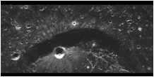
Figure 1. SAR image taken by Mini-RF on LRO of a portion of the Kopf impact crater. Ejected material on the rim of Kopf is from small interior crater. This material is not visible in Clementine or Lunar Orbiter images of this region.
The calibration of the Mini-RF instruments proved challenging for several reasons. No opportunities for pre-launch calibration of the complete radar system were available, which limited the ground calibration to separate characterizations of the radar electronics and antenna. Standard techniques used by Earth orbiters were not an option; there are no Amazon rain forests, nor specially placed radar reflectors available on the Moon. Therefore, the team employed a unique combination of experiments, designed specifically to measure the key calibration parameters. The Mini-RF approach provided for complete on-orbit radiometric and polarimetric radar calibrations via a combination of nadir and Earth-based measurements. A complete calibration usng only nadir measurements is possible if and only if the radar is hybrid-polarimetric, i.e. transmitting circular polarization, and receiving coherently orthogonal linear polarizations, such as H (Horizontal) and V (Vertical) [1]. The Mini-RF calibration effort included a direct characterization of the transmit and receive portions of the radars via Earth-based resources, so as to remove the assumption of perfect circularity of the transmitted signal from the calibration analysis. The two Mini-RF radars are the pioneers of the aforementioned hybrid-polarimetric architecture and of the associated calibration strategy.
Calibration Overview & Philosophy:
Polarimetric Calibration An extensive set of measurements produced the primary Mini-RF calibration parameters. They are the system antenna patterns, especially in the azimuth dimension, as well as the receiver V/H polarization amplitude ratios, and V relative to H phase shifts. These corrections represent the key polarimetric corrections used in the Mini-RF SAR data processing to produce quality CPR measurements. The CPR, or Circular Polarization Ratio, is the central Mini-RF parameter contributing towards NASA’s search for water-ice on the Moon. CPR is one of prime parameters permitting scientific analysis of the lunar surface [2]. For the purpose of CPR based science, the fundamental data product for each Mini-RF radar is the 2x2 coherency matrix of the backscattered field, as based on Stokes parameters. These elements are derived from the magnitudes of and relative phase between the two channels of the H and V polarized receiver. To be meaningful, these values must be relatively calibrated to produce a polarimetric calibrated radar. Hence, the focus of this report is on polarimetric calibration techniques.
On-Orbit Calibration Experiments The on-orbit calibration experiments measured the Mini-RF receive (Rx) and transmit (Tx) characteristics on separate days, using different Earth-based antennas, as the corresponding transmitter or receiver platforms. The Arecibo radio telescope in Puerto Rico (ART) acted as a transmitter to the Mini-RF Rx. The Green Bank Radio Telescope in West Virginia (GBT) received Mini-RF transmissions. For both, the spacecraft reoriented and slewed, such that the Mini-RF to Earth-antenna orientations varied for the azimuth versus elevation antenna axis cuts. Another event, an end-to-end experiment, rolled the spacecraft to align the Mini-RF radar antenna in a nadir-pointing orientation towards the Moon. Under this condition radar backscattering properties are such that both H and V polarizations retain their relative transmitted amplitude and phase balances in the returned signal, as compared to the transmitted signal; that is, the backscatter in the H and V channels remains statistically independent. This experiment allowed for a comparison of the piecewise Rx and Tx calibration responses with an end-to-end system measurement. In addition, piecewise, pre-launch measurements of phase and amplitude balances for the transmitter, receiver, and antenna chains provided a prediction on the sensitivity of these items to temperature variations. For the LRO Mini-RF, built-in loop-back measurements provided a means to compare on-orbit performance directly with pre-launch values.
Calibration Implementation: Once the above experiments are completed, and the calibration coefficients determined, the team remains mindful that some of the polarimetric calibration corrections must be applied before azimuth data compression algorithms in the SAR processor software; others can be applied afterwards. The azimuth antenna pattern is of the first type; it directly affects the relative amplitude of the individual SAR “looks” that are integrated to create the final output products. In contrast, variations found in the SAR elevation direction are essentially preserved and can be corrected at a later stage in the processing pipeline. Higher-order corrections in the radar’s performance due to temperature variations can be applied as fine-tuning of the first-order calibrations.
Mini-RF Forerunner (Ch-1) Calibration Results: Calibration results agreed well with pre-launch predictions. Summary results follow. Azimuth antenna patterns and Rx chain results are first-order corrections to the data. The actual transmitted field is a combination of LHC and RHC (Left Hand Circular, Right HC) polarizations, dominated by LHC, for both Mini-RFs.
Antenna Pattern Measurements. The antenna patterns revealed a 33.5˚offset from the spacecraft panel, versus 32.7˚ expected from ground measurements. Beam width was 4.8⁰ in azimuth and 8.5⁰ in elevation.
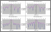
Figure 2. C-1 Mini-RF Antenna patterns, Ground measurements in blue, ART in pink, wider elevation axis pattern in top row, narrower azimuth axis at bottom, H-channels on left and V-channels on right.
Ch-1 Mini-RF Receiver Path Calibrations
ART Experiment 1/30/2009
|
Rx Chain Parameter |
Nominal Value |
|
V/H imbalance |
0.3 ± 0.2 dB |
|
V-H phase imbalance |
43.5˚± 1.5˚ |
Ch-1 Mini-RF Transmit Path Calibrations
GBT Experiment 2/28/2009
|
Tx Chain Parameter |
Nominal Value |
|
V/H imbalance |
-2.44 dB |
|
V-H phase balance |
-92.4˚ |
|
Axial Ratio |
2.46 dB |
Ch-1 Mini-RF End-to-End Nadir Results 1/18/2009
|
Parameter |
End-to-end prediction |
Observation |
|
V/H gain balance |
-2.14 ±0.25 dB |
-2.55±0.25 dB |
|
V-H phase balance |
-135.9˚± 1.5˚ |
-138˚± 2.7˚ |
Mini-RF LRO S-Band Calibration Results: Here antenna patterns and receiver results agreed generally well with pre-launch measurements. The transmitter balance differed from pre-launch predictions.
Antenna Pattern Corrections The antenna patterns verified correct alignment at a 47.8˚ offset with widths of 4.2˚ in azimuth and 12.2˚ in elevation.
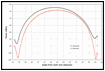
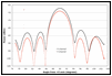
Figure 3. LRO Mini-RF Antenna patterns, H-channel measurements in blue, V in red, wider elevation axis pattern at left, narrower azimuth axis at right.
LRO/Mini-RF Receiver Path Calibrations
ART Experiment 8/17, 8/20, 9/13
|
Rx Chain Parameter |
Nominal Value |
|
V/H imbalance |
-1.75 ± 0.15 dB |
|
V-H phase imbalance |
183.1˚± 0.7˚ |
LRO/Mini-RF Transmit Path Calibrations,
GBT Experiment 8/23/2009
|
Tx Chain Parameter |
Nominal Value |
|
V/H imbalance |
-0.37 ± 0.25 dB |
|
V-H phase balance |
-105.2˚± 0.1˚ |
|
Axial Ratio |
2.38 ± 0.02 dB |
|
Polarization Ratio |
17.4 dB |
The actual transmitted field is a combination of LHC and RHC polarizations, dominated by LHC. The polarization ellipse is oriented at roughly 45 degrees between the Mini-RF horizontal and vertical axes.
LRO/Mini-RF End-to-End Nadir Results 7/16/2009
|
Parameter |
End-to-end prediction |
Nadir Observation |
|
V/H gain balance |
-2.12 ± 0.25 |
-1.8 ± 0.4 dB |
|
V-H phase balance |
108.3˚± 0.1˚ |
101.4˚± 2.7˚ |
Conclusions: The unique Mini-RF calibration effort successfully determined the first-order calibration coefficients for the Mini-RF Forerunner. Analysis of the LRO Mini-RF calibration parameters in S-Band from on-orbit events are in use by the SAR processor. X-Band on-orbit events are planned. Forerunner corrections are available and in use by the Mini-RF SAR processor and processing pipeline software. Successive applications of improved or higher-order calibrations are possible.
References: [1] R. K. Raney. (2007) IEEE Trans.Geos. Remote Sensing, 45, 3397-3404.
[2] LPSC XLI: Spudis P.D. et al.; Bussey D.B. et al.; Payne C.J. et al.; Thomson B.J. et al.; Neish C. D. et al. (2010).