MESSENGER Gamma Ray Spectrometer
Calibrated Data Record,
Reduced Data Record, and
Derived Analysis Product
Software Interface Specification
Version 1.51
November 18, 2015
Document Review
This document and the archive it describes have been through
PDS Peer Review and have been accepted into the PDS archive.
Patrick Peplowski, GRS Instrument Scientist, has reviewed
and approved this document.
Susan Slavney, PDS Geosciences Node Representative, has
reviewed and approved this document.
Susan Ensor, MESSENGER Science Operations Center Lead, has
reviewed and approved this document.
|
DATE
|
SECTIONS CHANGED
|
REASON FOR
CHANGE
|
REVISION
|
|
08/17/06
|
Added PDS labels
|
Draft
|
1.0b
|
|
08/21/06
|
Changed numbering scheme
|
Draft
|
1.0c
|
|
07/01/08
|
Corrected typos
|
Draft
|
1.3
|
|
10/29/08
|
All
|
Draft
|
1.4
|
|
10/29/08
|
All
|
Draft
|
1.5
|
|
11/03/08
|
All
|
Draft
|
1.6
|
|
02/10/09
|
All
|
Draft
|
1.7
|
|
03/03/09
|
All
|
Draft
|
1.8
|
|
03/10/09
|
All
|
Draft
|
1.9
|
|
03/19/09
|
All
|
Draft
|
1.10
|
|
03/23/09
|
All
|
Draft
|
1.11
|
|
03/24/09
|
All
|
Draft
|
1.12
|
|
04/03/09
|
All
|
Draft
|
1.13
|
|
04/07/09
|
All
|
Draft
|
1.14
|
|
04/14/09
|
All
|
Draft
|
1.15
|
|
04/14/09
|
All
|
Draft
|
1.16
|
|
04/17/09
|
All
|
Added search indexes info
|
1.17
|
|
04/29/09
|
All
|
Added NAME attribute to OBJECTs in GRS_ENG LBL file.
Changed GRS_ENG.FMT file to have raw data type of
MSB_INTEGER.
|
1.18
|
|
05/08/09
|
All
|
Added 3 S/C orientation columns to the GRS_CAL_AC,
GRS_CAL_RAW and GRS_CAL_SH files. Added Susan Slavney changes.
|
1.19
|
|
06/12/09
|
All
|
Modified Appendix with GRS_CAL_AC.FMT, GRS_CAL_RAW.FMT and
GRS_CAL_SH.FMT to have spectra with each item being an IEEE_REAL 4 byte float
instead. Also modified the archive’s DATA sub-directory under the month
sub-directory to be named after the day of the month not the day of the year.
|
1.20
|
|
8/31/09
|
All
|
Modified Document to reflect comments from the PDS Peer
Review
|
1.21
|
|
1/19/10
|
6.7
|
Added md5 files
|
1.22
|
|
2/7/10
|
8.4, 8.5.4, 8.5, 8.7.4, document headers
|
Updated engineering conversions. Removed DETECTOR_ID from
the ENG format file. Updated index description. Minor updates to document
headers.
|
1.23
|
|
2/8/10
|
TOC, 5.6, 8.5, 8.7.1, 8.7.4
|
Updated TOC page numbers. Edited software description.
Minor sample label edits to match delivered files. Sample index.lbl
formatting, fixed VOLUME_ID. Edited column 13 NAME in GRS_CAL_RAW.FMT and
column 5 DESCRIPTION in GRS_ENG.FMT to match delivered files. Additional
minor edits/formatting.
|
1.24
|
|
2/11/10
|
6.7.1
|
Changed name of SOFTWARE directory file from software.txt
to softinfo.txt.
|
1.25
|
|
12/14/10
|
6.5, 6.8.2, 8.5.4, 8.7.4
|
Added new Shield data product
|
1.26
|
|
5/16/11
|
5.2
|
Added GRS_CAL_SH2 into table and added a description of
the flight software change
|
1.26
|
|
5.16.11
|
6.2.1, 6.3.1. 6.4.1, 6,5,1
|
Removed the phrase (see Section 6, Detailed Data
Product Specifications, on page 20 for each binary file)
|
1.26
|
|
5/16/11
|
8.5.4
|
Added the keyword STANDARD_DATA_PRODUCT_ID to the sample
label, correct column count to 45
|
1.26
|
|
6/2/11
|
8.6, 8.7
|
Change “periherm” to “apoherm” in descriptions of orbit
start time
|
1.27
|
|
6/14/11
|
Document Review
8.6
|
Added document review information.
Adjusted table formatting.
|
1.28
|
|
8/4/11
|
All
|
Changed GRS_CAL_SH_2 to GRS_CAL_SH2.
|
1.29
|
|
3/16/12
|
6.7, 6.9.2, 8.5.6, 8.6, 8.7.6
|
Added RDR_SUM data type
|
1.30
|
|
5/16/12
|
2, 4, 5.5
|
Change “Data Management and Science Analysis Plan” to
“Data Management and Archiving Plan:
|
1.31
|
|
5/22/12
|
Document Review
|
Change MESSENGER GRNS reviewer to Patrick Peplowski
|
1.32
|
|
6/7/12
|
8.5.6, 8.7.7, 8.6, 6.7, 6.9.2
|
Add new columns to RDR_SUM product, added RDR product size,
added information about sum types
|
1.33
|
|
8/21/12
|
8.6, 8.7.7
|
Correct type of gain and offset in RDR_SUM.
|
1.34
|
|
9/27/12
|
6.7.1
|
Minor corrections from peer review liens.
|
1.35
|
|
12/7/12
|
8.6, 8.72-8.75
|
Revised BAD_DATA_FLAG descriptions.
|
1.36
|
|
1/15/13
|
8.7.7
|
Fixed units in GRS_RDR_SUMS.FMT.
|
1.37
|
|
2/4/13
|
All
|
Editorial changes
|
1.38
|
|
4/22/13
|
1.1
|
Editorial changes.
|
1.39
|
|
6/7/13
|
All
|
Added new count rate and abundance map data product.
|
1.40
|
|
6/12/13
|
Document Review, Table 6.2
|
Revised “Document Review” section and Table 6.2. Version
submitted for DAP peer review.
|
1.41
|
|
10/4/13
|
5.2, 6.6, 6.7, 8.5.5, 8.5.6, 8.7.5, 8.7.6
|
Added description of new data products resulting from
flight software update.
|
1.42
|
|
10/16/13
|
6.1.3, 6.10.1, 6.12.1, 8.5.9, 8.5.10
|
DAP peer review revisions.
|
1.43
|
|
11/21/13
|
5.1, 6.7.1, 8.5.6, 8.6, 8.7.5, 8.7.6
|
Edits resulting from review of new shield sensor products.
|
1.44
|
|
1/10/14
|
8.5.9
|
Minor edits.
|
1.45
|
|
5/21/14
|
8.4, 8.5.5, 8.5.6, 8.6, 8.7.5, 8.7.6
|
Removed references to “AZI_ANG”, added “DEADTIME_FRAC” to
CDR descriptions. Revised associated SCR and SH3 CDR sample labels and format
files.
|
1.46
|
|
11/13/14
|
8.5.5, 8.5.6, 8.5.10, 8.7.5, 8.7.6
|
Revised “ALTITUDE” column in SCR and SH3 CDR format files.
Updated sample labels accordingly. Replaced sample index label with current
version.
|
1.47
|
|
10/16/15
|
8.6, 8.7
|
Updated data column descriptions, FMT files.
|
1.48
|
|
10/28/15
|
8.5, 8.7, TBD Log
|
Matched sample labels and format files with archived
files. Removed TBD log.
|
1.49
|
|
11/13/15
|
All
|
Editorial updates to reflect completion of data
acquisition and PDS deliveries.
|
1.50
|
|
11/18/15
|
5.3.2, 6.7.1
|
Minor typo and editorial fixes.
|
1.51
|
Change Log. 2
1 Purpose and Scope of Document 9
1.1 Purpose. 9
1.2 Scope. 9
2 Applicable Documents. 9
3 Relationships with Other
Interfaces. 10
4 Roles and Responsibilities. 10
5 Data Product Characteristics
and Environment 10
5.1 Instrument
Overview.. 10
5.2 Data
Product Overview.. 12
5.3 Data
Processing. 14
5.3.1 Data
Processing Level 14
5.3.2 Data
Product Generation. 14
5.3.3 Data
Flow.. 14
5.3.4 Labeling
and Identification. 16
5.4 Standards
Used in Generating Data Products. 16
5.4.1 PDS
Standards. 16
5.4.2 Coordinate
Systems. 16
5.4.3 Data
Storage Conventions. 19
5.5 Data
Validation. 19
5.6 Software. 20
6 Detailed Data Product
Specifications. 20
6.1 Common
Elements of Calibrated Data. 20
6.1.1 Handling
Errors. 20
6.1.2 Geometric
Elements. 20
6.1.3 PDS
Label File Format 21
6.1.4 Table
File Formats. 26
6.1.5 Format
File Keyword Definitions. 26
6.2 Raw
Spectra – GRS_CAL_RAW... 28
6.2.1 Data
Product Structure and Organization. 28
6.2.2 Data
Format Descriptions. 28
6.2.3 File
Naming Conventions. 28
6.2.4 Label
Description. 29
6.3 Anticoincidence
Spectra – GRS_CAL_AC.. 29
6.3.1 Data
Product Structure and Organization. 29
6.3.2 Data
Format Descriptions. 30
6.3.3 File
Naming Conventions. 30
6.3.4 Label
Description. 30
6.4 Shield
Spectra – GRS_CAL_SH.. 31
6.4.1 Data
Product Structure and Organization. 31
6.4.2 Data
Format Descriptions. 31
6.4.3 File
Naming Conventions. 31
6.4.4 Label
Description. 32
6.5 Shield
Spectra – GRS_CAL_SH2. 32
6.5.1 Data
Product Structure and Organization. 32
6.5.2 Data
Format Descriptions. 33
6.5.3 File
Naming Conventions. 33
6.5.4 Label
Description. 33
6.6 Shield
Spectra – GRS_CAL_SH3. 34
6.6.1 Data
Product Structure and Organization. 34
6.6.2 Data
Format Descriptions. 34
6.6.3 File
Naming Conventions. 34
6.6.4 Label
Description. 35
6.7 Shield
Spectra – GRS_CAL_SCR.. 35
6.7.1 Data
Product Structure and Organization. 35
6.7.2 Data
Format Descriptions. 36
6.7.3 File
Naming Conventions. 36
6.7.4 Label
Description. 36
6.8 Engineering
Data – GRS_ENG.. 37
6.8.1 Data
Product Structure and Organization. 37
6.8.2 Data
Format Descriptions. 38
6.8.3 File
Naming Conventions. 38
6.8.4 Label
Description. 39
6.9 Summed
Spectra – GRS_RDR_SUM... 39
6.9.1 Data
Product Structure and Organization. 39
6.9.2 Data
Format Descriptions. 40
6.9.3 File
Naming Conventions. 40
6.9.4 Label
Description. 41
6.10 Count
Rate and Abundance Maps – GRS_DAP. 41
6.10.1 Data
Product Structure and Organization. 41
6.10.2 Data
Format Descriptions. 42
6.10.3 File
Naming Conventions. 42
6.10.4 Label
Description. 43
6.11 Archive
Volume. 43
6.12 Directory
Structure and Contents for GRS Archive Volume. 43
6.12.1 Directory
Contents. 44
6.12.2 Data
Product Sizes. 46
7 Product Delivery. 47
7.1 Product
Delivery Mechanism.. 47
7.2 Product
Redelivery. 47
8 Appendices. 48
8.1 Appendix:
SPICE Kernel Files Used in MESSENGER Data Products. 48
8.2 Appendix:
CODMAC/NASA Definition of Processing Levels. 49
8.3 Appendix:
GRS Glossary and Acronym List 50
8.4 Appendix:
Engineering Transformations. 52
8.5 Appendix:
GRS PDS Label Files. 54
8.5.1 GRS_CAL_RAW... 54
8.5.2 GRS_CAL_AC.. 55
8.5.3 GRS_CAL_SH.. 56
8.5.4 GRS_CAL_SH2. 57
8.5.5 GRS_CAL_SH3. 58
8.5.6 GRS_CAL_SCR.. 59
8.5.7 GRS_ENG.. 60
8.5.8 GRS_RDR_SUM... 75
8.5.9 GRS_DAP. 76
8.5.10 INDEX.. 78
8.6 Appendix:
GRS CDR/RDR Data Columns. 81
8.7 Appendix:
GRS PDS FMT Files. 89
8.7.1 Appendix:
GRS_CAL_RAW.FMT. 89
8.7.2 Appendix:
GRS_CAL_AC.FMT. 99
8.7.3 Appendix:
GRS_CAL_SH.FMT. 109
8.7.4 Appendix:
GRS_CAL_SH2.FMT. 116
8.7.5 Appendix:
GRS_CAL_SH3.FMT. 125
8.7.6 Appendix:
GRS_CAL_SCR.FMT. 131
8.7.7 Appendix:
GRS_ENG.FMT. 137
8.7.8 Appendix:
GRS_RDR_SUMS.FMT. 138
This document provides users of the MESSENGER Gamma-Ray
Spectrometer (GRS) data products with a detailed description of the GRS
instrument, CDR/RDR/DAP (Calibrated Data Record/Reduced Data Record/Derived
Analysis Product) generation, validation, and storage. Note that the Gamma Ray
and Neutron Spectrometer instruments were generally referred to as the GRNS
instrument. However, they were two separate sensors, each with its own EPU,
and the data products are described within the specific Software Interface
Specification (SIS) of each sensor.
The goal of this document is to provide thorough and
complete information so that Planetary Data System (PDS) users can read and
understand the data products long after the completion of the MESSENGER
mission. As such, this document provides a common reference for scientists,
data analysts, software engineers, and researchers to access and understand the
MESSENGER Gamma Ray Spectrometer CDR/RDR/DAP PDS archived data.
This document describes the intermediate and advanced data
products for the MESSENGER GRS. These data products correspond to National
Research Council Committee on Data Management and Computation (CODMAC) levels 3-5.
These data levels are described more fully in Section 8.2, Appendix:
CODMAC/NASA Definition of Processing Levels.
The MESSENGER GRS CDR/RDR/DAP SIS is responsive to the
following documents:
·
Planetary Data System Standards Reference, February 27, 2009,
Version 3.8. JPL D-7669, Part-2.
·
Planetary Data System Archive Preparation Guide, April 1, 2010,
Version 1.4, JPL D-31224.
·
GRS Flight Software Specification, Draft Dec. 15, 2003.
·
MESSENGER Experiment Data Record (EDR) Software Interface
Specification for the Gamma Ray Spectrometer.
·
MESSENGER Data Management and Archiving Plan. The Johns Hopkins
University, APL.
·
MESSENGER Project Archive Generation, Validation, and
Distribution Plan.
·
MESSENGER Mercury: Surface, Space Environment, Geochemistry,
Ranging; A mission to Orbit and Explore the Planet Mercury, Concept Study,
March 1999.
·
[PLR] Appendix 7 to the Discovery Program Plan; Program Level
Requirement for the MESSENGER Discovery project, June 20, 2001.
·
The MESSENGER Gamma-Ray and Neutron Spectrometer, Space Science
Reviews 131,
339-391,
2007.
The GRS CDR/RDR/DAP data products are dependent on the GRS Experiment
Data Record (EDR) data products. Changes to the EDR product have required
revisions to the associated CDR/RDR/DAP products. The GRS CDR/RDR/DAP data
products are also dependent on valid SPICE Kernel generation for timing and
spatial information. Changes or revisions to the SPICE Kernel have also
required revisions to the GRS CDR/RDR/DAP products. Changes to data processing
programs (see Section 6, Detailed Data Product Specifications) that
convert EDR data to CDR/RDR/DAP data have also resulted in revised CDR/RDR/DAP
data products.
The roles and responsibilities of the instrument teams,
Applied Physics Laboratory (APL), Applied Coherent Technology (ACT), and the
Planetary Data System (PDS) are defined in the MESSENGER Data Management and Archiving
Plan.
The Mercury Surface, Space ENvironment, GEochemistry, and
Ranging (MESSENGER) mission was designed to orbit Mercury following one Earth
flyby, two of Venus, and three of Mercury. It launched in August 2004 and
achieved orbit insertion around Mercury on 18 March 2011. Initial data
collection began during the three flybys of Mercury and consisted primarily of
global mapping and measurements of the surface, atmosphere, and magnetosphere
composition. The nominal one-Earth-year long mission ended on 17 March 2012.
This was immediately followed by the start of a one-year-long extended mission.
A second and final two-year-long second extended mission ended on 30 April,
2015, when the MESSENGER spacecraft impacted the surface as expected. MESSENGER
orbital observations provide data to answer questions about the nature and
composition of Mercury’s crust, tectonic history, structure of the
atmosphere/magnetosphere, and the nature of the polar caps.
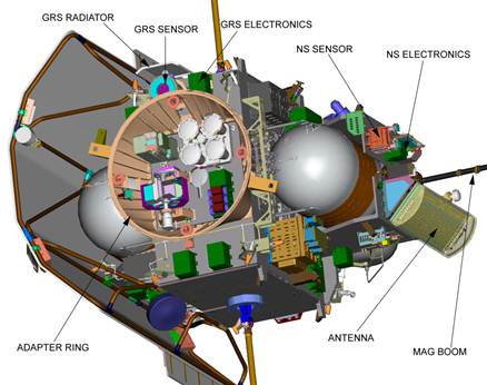
The Gamma Ray Spectrometer (GRS) instrument onboard the
MESSENGER spacecraft was designed to observe the spectrum of gamma rays emitted
from Mercury’s surface in the energy range from 0.1 MeV to 10 MeV. Gamma rays
are produced either directly from radioactive decay (of K, Th, U) or indirectly
when activated by the cosmic ray background. The relatively low absorption rate
of these gamma rays allows the estimation of the surface composition to depths
of ~10’s of cm, depending on the energy
of the gamma ray.
The GRS consisted of two separate sensors. Gamma-ray
measurements were made using a high-purity germanium (HPGe) cylindrical
semiconductor crystal encapsulated in aluminum. The HPGe was surrounded by a
shield of plastic scintillator (BC-454) that is sensitive to charged particles
and neutrons. The encapsulated HPGe was contained within a cryostat made of a
nest of gold-plated cans and suspended by a network of Kevlar strings. This was
done to provide thermal and electrical isolation. The HPGe required a
mechanical cryocooler to maintain the required ~90K temperatures in order to
detect gamma rays. The cryocooler failed on 15 June, 2012 after approximately
9,000 hours of operation. This exceeded the expected 8,000 hour lifetime of the
cooler. Following the cooler failure, new flight software was uploaded to the
GRS on 25 February, 2013 for the purpose of optimizing the instrument for
neutron and charged particle measurements with the BC-454 shield. These changes
included the addition of a high time cadence measure of the local particle
flux, which is useful for characterizing the charged particle environment near
Mercury. ACS measurements were acquired nearly continuously until the end of
the mission.
When gamma rays interact with the bulk HPGe, a charge is
generated. The electrical charge was amplified, measured, and then digitally
converted into one of the 16,384 (214) channels (bins) of the
detector. After a specified accumulation time, a histogram was produced that
shows the distribution of events (number of strikes) that accrued during that
period as a function of energy (channel number). Due to the low count rates
usually encountered, accumulation times of minutes to hours are normal. The raw
science data product is the counts in each in each of the 16,384 bins after
this accumulation period. This histogram is counted as one gamma ray spectrum
(GRS_CAL_RAW product).
In addition to the HPGe, the GRS used the plastic
scintillator as an anticoincidence shield, primarily to reduce the background
signal in the HPGe from cosmic-ray-originating neutrons and gamma rays created
within the spacecraft. In a scintillator, the interaction of the gamma ray
results in a brief fluorescence, with an intensity proportional to the energy.
The light pulse was amplified by a photo-multiplier tube and then buffered, shaped
and digitized with a separate analysis chain from the HPGe. The shield
scintillator has a much lower energy resolution than the HPGe and its spectrum
has no well-defined energy peaks, so detected events in the shield are binned
to only 1024 channels by the EPU (GRS_CAL_AC product). Scintillator-incident
neutrons were detected though the 10B(n,g)
reaction, as the BC-454 is enriched in 10B. Additionally, charged
particles may be detected though the ionization they induce while passing
through the scintillator.
If events were found to occur in both detectors within some
short time interval, a coincidence condition is flagged. This may have been
caused by a single high-energy particle depositing energy in both detectors as
it passed through or by secondary photons created after an initial gamma ray or
neutron interaction or by two independent events occurring simultaneously
(false coincidence or “accidental”). In either case, the energies measured
cannot be related to the initial event without additional interpretation.
Separate spectra are maintained to accumulate both raw (unprocessed) and
anticoincidence HPGe events (GRS_CAL_SH product).
The 25 February 2013 flight software upload included the
addition of a new data product, called “shield count rate”. This product
measures the total count rate at high time cadence (10 ms) in order to provide
new insights into the charged particle environment around Mercury, particularly
the energetic electron events. The total count rate on the detector was
measured every 10 ms and stored in a 16,384 channel long array. For short
integration periods, this array is too large and the remaining values are set
to zero. When a data integration period would require more than 16,384
channels, the values past this length are stored in the final channel. The
first approximately 50 entries of the shield count rate product are always
zero, and reflect the 0.5-second-long interval at the beginning of the
accumulation period during which the GRS electronics busy performing other tasks
and are unable to processes the total shield count rates.
The GRS CDR/RDR/DAP archive includes nine data products: 7 CDR,
1 RDR, and 1 DAP. A CDR data file contains all the data of a given type
recorded for a given day of the Earth year. RDR and DAP products contain summed
information acquired over a range of times. The data products are as follows:
|
Data Product
|
Product Description
|
Example Filename
|
|
|
·
Detached PDS label file.
·
Spectra data file – HPGe raw spectra, and associated timing,
spatial, and engineering data in binary table.
|
GRS_CRA2008265ZZZ.DAT
See section 6.2.3 for details.
|
|
|
·
Detached PDS label file.
·
Spectra data file – HPGe anti-coincident spectra and associated
timing, spatial, and engineering data in binary table.
|
GRS_CAC2008265ZZZ.DAT
See section 6.3.3 for details.
|
|
|
·
Detached PDS label file.
·
Shield Spectra data file – shield spectra and associated
timing, spatial, and engineering data in binary table. This product was
generated prior to September 17, 2010.
|
GRS_CSH2008265ZZZ.DAT
See section 6.4.3 for details.
|
|
|
·
Detached PDS label file.
·
Shield Spectra data file – shield spectra and associated
timing, spatial, and engineering data in binary table. This product was
generated after September 17, 2010.
|
GRS_CS22008265ZZZ.DAT
See section 6.5.3 for details.
|
|
|
·
Detached PDS label file.
·
Shield Spectra data file – shield spectra and associated
timing, spatial, and engineering data in ASCII table. This product was
generated after March 17, 2013.
|
GRS_CS32013151ZZZ.TAB
See section 6.6.3 for details.
|
|
|
·
Detached PDS label file.
·
Shield count rate file – shield count rate and associated
timing, spatial, and engineering data in ASCII table. This product was
generated after March 17, 2013.
|
GRS_CSC2013091ZZZ.TAB
See section 6.7.3 for details.
|
|
|
·
Detached PDS label file.
·
Engineering data file – GRS instrumental engineering data in
binary table.
|
GRS_E012008265ZZZ.DAT
See section 6.8.3 for details
|
|
|
·
Detached PDS label file.
·
Spectral Sum in binary table.
|
GRS_RS12008265ZZZ.DAT
See section 6.9.3 for details
|
|
|
·
Detached PDS label file.
·
Map of gamma-ray count rates or elemental abundances derived
from summed GRS data.
|
GRS_DAP_K_ABD_MAP.JP2
See section 6.10.3 for details
|
Each MESSENGER GRS CDR/RDR product consists of three files.
One file contains the data itself and is arranged in binary or ASCII table
format. Another file is a label file that describes the content of the data
file. The label file defines the start time and end time of the observation,
product creation time, etc. It does not describe the structure of the data file
itself. Instead, the PDS label file contains a reference pointer to a separate
format file (*.FMT). The format file describes the structure of the table and
each of the different fields within the table. This format file resides in the
top level of a LABEL directory in a data archive volume, because it applies to
the structure of all the table files. The GRS DAPs do not contain associated
format files; rather, the file structure is fully described by the label.
On 17 September 2010, new flight software was loaded onto
the spacecraft to produce the GRS_CAL_SH2 data format. The new software added
fast-neutron detection capability to the GRS by employing a new mode of operation
between the anticoincidence shield and the germanium detector. The CAL_SH
column of the GRS_CAL_SH data product was transformed into 12 separate columns
in the GRS_CAL_SH2 data product. These columns are described in section 8.7.4.
The column range is from NUM_BUFFERED_EVENTS through SHIELD_FAST.
Measurement of the fast-neutron
flux near the GRS is needed to reduce the uncertainty in the spacecraft
contribution to important elemental lines in the GRS gamma-ray spectrum. The
previous shield spectrum data product was a full 1024 bins and extended well
beyond the region of interest. The four thermal and fast events spectra are all
obtained using coincidence events with the HPGe detector in the 478-keV region
of the HPGe spectrum. The 478-keV region contains the gamma-ray emitted in a
thermal neutron capture reaction with 10B present in the
borated-plastic shield. It was found that the spectra of these coincidence
events best isolated the neutron signal, while minimizing the gamma-ray
background, but it is not certain what fraction of these events are actually
neutrons or gamma-rays. The HPGE_THERMAL and SHIELD_THERMAL events spectra
contain events within a narrow ± 0.1μs coincidence window and likely
represent mostly thermal neutrons. The HPGE_FAST and SHIELD_FAST events spectra
contain events with positive coincidence times > 0.1μs and likely
represent mostly fast neutrons. The HPGE_THERMAL and HPGE_FAST events spectra
provide the corresponding 478-keV HPGe peak along with sufficient background
channels on either side of the peak to allow background subtraction, while the
SHIELD_THERMAL and SHIELD_FAST events spectra contain the corresponding shield
spectrum.
On 25 February 2013, new flight software was loaded onto the
spacecraft. This software added the shield count rate data product, and changed
the gain of the anti-coincidence shield in order to facilitate peak fitting of
the GRC_CAL_SH2 spectra. Additionally, the format of the gain-modified SH2 EDR
was changed, resulting in the SH3 product.
The CODMAC data level numbering system is used to describe
the processing level of the GRS data products. GRS CDR/RDR products are
considered a CODMAC “Level 3” (Calibrated) or NASA “Level 1A,” which are edited
data that are still in units produced by the instrument, but have been
transformed (e.g., calibrated, rearranged) in a reversible manner and packaged
with needed ancillary and auxiliary data (e.g., temperatures with calibration
equations applied). The GRS DAP products are a CODMAC "Level 5"
(Derived) or NASA "Level 3," which are derived results such as maps,
reports, graphics, etc. For a more detailed description, see Section 8.2, Appendix: CODMAC/NASA Definition of Processing Levels.
The GRS CDR/RDR files with the exception of the SH3 and SCR
CDRs were produced by the University of Arizona (UA) and provided to the
MESSENGER Science Operations Center (SOC) operated jointly by APL and Applied
Coherent Technology Corporation (ACT). The University of Arizona was
responsible for converting the data to the proper PDS labeled format, with the
exception of the SH3 and SCR products, which were produced by APL. The CDR/RDR
data products were made available to the MESSENGER Science Team for initial
evaluation and validation. At the end of the evaluation and validation period,
the data were organized and stored on the best determined media and made
available to the PDS for distribution to the science community. These products
are used for engineering support, direct science analysis, and construction of
other science products. DAPs were created by APL and ACT.
The MESSENGER SOC planned data acquisition during the
operational period and generated and validated data archives under the auspices
of the MESSENGER Project Scientist. The SOC supported and worked with the MOC, the
Science Team, instrument scientists, and the PDS.
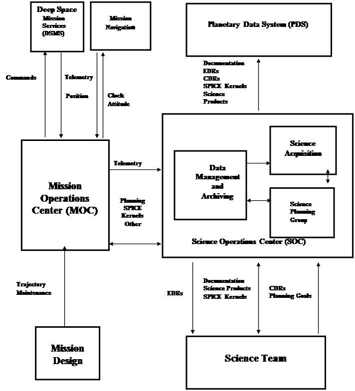
A primary data server residing at the SOC, located at APL,
served as the data storage facility for all MESSENGER instruments. Inputs to
the SOC consisted of telemetry in the form of Consultative Committee for Space
Data Systems (CCSDS) packets. Files were received from the SOC and delivered to
the SOC via ftp. (See figure 1, MESSENGER data flow.) In the case of the GRS
CAL_RAW, CAL_AC, CAL_SH, CAL_SH2, ENG, and RDR_SUM data products, UA received
GRS EDR data from the SOC, transformed the data into valid CDR/RDR data products,
and returned the data to the SOC for storage and distribution. CAL_SH3,
CAL_SCR, and DAP products were produced at APL and returned to the SOC for
storage and distribution.
Figure
1 MESSENGER data flow
There is a corresponding detached PDS label file for each
GRS CDR/RDR/DAP data file. See Section 6, Detailed Data Product
Specifications for the sample PDS label files and a complete description of
each label format. Detached means that the label file is separate from the
data file, as opposed to being in the header portion of the data file.
The data set ID assigned by PDS to the GRS CDR/RDR data set
is “MESS-E/V/H-GRNS-3-GRS-CDR-V1.0”. The data set ID assigned by PDS to the
GRS DAP data set is “MESS-E/V/H-GRNS-5-GRS-DAP-V1.0”.
The GRS CDR/RDR/DAP data products comply with the Planetary
Data System standards for file formats and labels as specified in the PDS
Standards Reference.
The GRS CDR/RDR data products include:
Data File - A binary or ASCII table object containing the
data.
Detached Label File - Serves as a high-level description of the parameters that
correspond to the table object.
A pointer to a FORMAT file, which describes the structure of the table file.
The GRS DAP data product includes:
Data File - An image object containing the data.
Detached Label File - Describes the parameters and structure of the image
object.
There are two coordinate systems in use:
- the celestial reference system used for target and
spacecraft position and velocity vectors and camera pointing, and
- the planetary coordinate system for geometry vectors and
target location.
The celestial coordinate system is J2000 (Mean of Earth
equator and equinox of J2000). The planetary coordinate system is planetocentric.
The planetocentric system has an origin at the center of mass of the body. The
planetocentric latitude is the angle between the equatorial plane and a vector
connecting the point of interest and the origin of the coordinate system.
Latitudes are defined to be positive in the northern hemisphere of the body,
where north is in the direction of Earth's angular momentum vector, i.e.,
pointing toward the hemisphere north of the solar system invariant plane.
Planetocentric longitude is measured around the equator of the body from a
prime meridian defined and adopted by international agreement, i.e., Seidelmann
et al 2003. Longitudes increase toward the east making the planetocentric
system right-handed. Radius is the distance from the planetary body's center of
mass to the point of interest.
The list below describes the computational assumptions for
the geometric and viewing data provided in the PDS label:
·
The mid-point time of observation is used for the geometric element
computations. (The mid-point is calculated using the Start and End times from
the EDR set.)
Label parameters reflect observed, not true, geometry. Therefore, light-time
and stellar aberration corrections are used as appropriate.
The inertial reference frame is J2000 (also called
EME2000).
Latitudes and longitudes are planetocentric.
The "sub-point" of a body on a target is defined
by the surface intercept of the body-to-target-center vector. This is not the
closest point on the body to the observer where the observer is the spacecraft,
MESSENGER.
Distances are in km, speeds in km/sec, angles, in degrees,
angular rates in degrees/sec, unless otherwise noted.
Angle ranges are 0 to 360 degrees for azimuths and local
hour angle. Longitudes range from 0 to 360 degrees (positive to the East).
Latitudes range from -90 to 90 degrees.
SPICE kernel files are used in the geometric parameters
(See Appendix: SPICE Kernel Files Used in MESSENGER Data Products.)
The spacecraft attitude during orbits and flybys is
defined by two additional coordinate systems, the GRS LVLH (Local Vertical
Local Horizontal) frame and the spacecraft fixed frame, and by the rotation of
the spacecraft frame with respect to the GRS LVLH frame. The GRS LVLH frame is
illustrated in the figure below.

In the GRS LVLH frame, the Z axis is aligned with the
vector from the spacecraft to the planet center (the nadir direction), the Y
axis is the negative of the cross product of the position and velocity vectors
(into the plane of the paper in the illustration), and the X axis points in the
instantaneous direction of motion, completing a right-handed coordinate system.
The spacecraft fixed frame is illustrated in the figure
below. The Z axis is along the viewing direction of the instrument deck inside
the adapter ring and of the GRS just outside the adapter ring, the Y axis is
directed from the spacecraft along the magnetometer boom, and the X-axis is
parallel to the solar panel booms, forming a right-handed coordinate system.
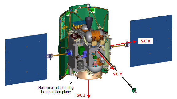
The spacecraft attitude is specified by the rotation of the spacecraft fixed
frame Z axis in the GRS LVLH frame and a twist angle about the Z axis. The Z
axis rotation is given by a nadir angle and an azimuth angle, where the nadir
angle is 0 degrees when the spacecraft Z axis points along the + Z LVLH axis
and 180 degrees when it points along –Z in the LVLH frame, and the LVLH azimuth
angle is measured counterclockwise about the Z LVLH axis from the X LVLH axis.
The twist angle is measured positive about the +Z spacecraft axis.
The data are organized following PDS standards. The CAL_RAW,
CAL_AC, CAL_SH, CAL_SH2, ENG, and RDR_SUM data are stored in binary files as
floating-point, signed and unsigned integer data in most-significant-first
(big-endian) byte order. The CAL_SH3 and CAL_SCR data are stored as ASCII
files. The DAPs are stored as jpeg2000 image files. See jp2info.txt in the
DOCUMENT directory for additional information on the JP2 data format.
The GRS CDR/RDR/DAP data products were validated by the GRS
Instrument Scientist for science content and for compliance with PDS archive
standards.
The GRS CDR/RDR/DAP data products and documentation were
submitted to a peer review committee for science review according to PDS
policy.
As PDS-compliant tables, most CDR/RDR data can be read using
the PDS-supplied program NASAView and other software designed to read PDS data.
However, NASAView will not read GRS engineering files because it does not
support a one-label-to-many-files relationship. Since NASAView cannot support
the GRS engineering CDRs, the GRS team supplies software to read these files.
This software is available from the PDS Geosciences node. (See softinfo.txt in
the SOFTWARE directory for details.) NASAView is available at no charge from
the PDS website http://pds.nasa.gov. The
information in the PDS labels includes complete software-readable descriptions
of data file formats, so that users may write custom software to read the
products if desired.
Please refer to jp2info.txt located in the DOCUMENT
directory for information on software to view the DAP JP2 files.
Even with data validation procedures applied to the volumes,
it is inevitable that errors will be introduced into the archive. A plan is
required to handle errors discovered in data volumes that have already been
produced.
As errors were discovered, they were reported to the GRS
data processing facility. The files were corrected and sent on to the PDS. A
text file called “ERRATA.TXT” located in the top level of the data volume was maintained
to track and document all discovered errors. The keywords PRODUCT_VERSION_ID
and PRODUCT_CREATION_TIME were updated in the PDS labels of corrected files.
The timing and spatial information that is packaged with the
GRS CDR/RDR/DAP data products are the timing and spatial values derived from
the appropriate SPICE kernels collected for each day of the mission. SPICE is
an acronym for Spacecraft, Planet, Instrument, C-matrix,
and Event kernels. SPICE kernels are provided by the Navigational
Ancillary Information Facility (NAIF) at the Jet Propulsion Laboratory, and are
the standard for all timing and spatial data transformations.
Below are the keyword definitions for the detached PDS label
files:
A_AXIS_RADIUS
Provides the value of the semimajor axis of the ellipsoid
that defines the approximate shape of a target body.
B_AXIS_RADIUS
Provides the value of the intermediate axis of the
ellipsoid that defines the approximate shape of a target body.
C_AXIS_RADIUS
Provides the value of the semiminor axis of the ellipsoid
that defines the approximate shape of a target body.
CENTER_LATITUDE
Provides a reference latitude for certain map
projections.
CENTER_LONGITUDE
Provides a reference longitude for certain map
projections.
COLUMNS
Identifies the number of columns (fields) in a table.
COORDINATE_SYSTEM_NAME
Provides the full name of the coordinate system to which
the state vectors are referenced, in this case "MEAN EARTH/POLAR AXIS OF
DE421".
COORDINATE_SYSTEM_TYPE
One of the three basic types of coordinate systems, in
this case "BODY-FIXED ROTATING".
DATA_SET_ID
Uniquely identifies the CDR/RDR/DAP file as part of a
volume collection, organized by sensor, mission phase, and version number. The
GRS CDR/RDR DATA_SET_ID is “MESS-E/V/H-GRNS-3-GRS-CDR-V1.0” and the GRS DAP
DATA_SET_ID is “MESS-E/V/H-GRNS-5-GRS-DAP-V1.0”.
^DATA_SET_MAP_PROJECTION
Pointer to the data set map projection catalog file.
DERIVED_MINIMUM
Indicates the smallest value occurring in a given
instance of the data object after the application of a scaling factor and/or
offset.
DERIVED_MAXIMUM
Indicates the largest value occurring in a given instance
of the data object after the application of a scaling factor and/or offset.
DESCRIPTION
Specifies a description of the object.
DETECTOR_ID
The detector_id element
identifies a particular instrument detector.
EASTERNMOST_LONGITUDE
For Planetocentric coordinates
and for Planetographic coordinates in which longitude increases toward the
east, the easternmost (rightmost) longitude of a spatial area (e.g.,a map,
mosaic, bin, feature or region)
is the maximum numerical value
of longitude unless it crosses the Prime Meridian.
ENCODING_TYPE
Indicates the type of
compression or encryption used for data storage.
ENCODING_TYPE_VERSION_NAME
Indicates the version of a standard or specification with
which a particular ENCODING_TYPE complies.
FILE_NAME
Provides the location
independent name of a file.
FILE_RECORDS
Indicates the number of physical file records in the
detached data file.
^IMAGE
Pointer to the image data file.
INSTRUMENT_HOST_NAME
A unique identifier for (name
of) the spacecraft on which the instrument is hosted, in this case "MESSENGER".
INSTRUMENT_ID
Unique ID associated with the instrument, in this case "GRS".
INSTRUMENT_NAME
Full, unabbreviated name of the instrument, in this case "GAMMA
RAY SPECTROMETER".
INTERCHANGE_FORMAT
Specifies the table format, binary or ASCII.
KEYWORD_LATITUDE_TYPE
Identifies the type of
latitude (planetographic or planetocentric) used in the labels, in this case it
is planetocentric.
LINE_FIRST_PIXEL
Provides the line index for the
first pixel that was physically recorded at the beginning of the image array.
LINE_LAST_PIXEL
Provides the line index for
the last pixel that was physically recorded at the end of the image array.
LINE_PROJECTION_OFFSET
Provides the line offset value
of the map projection origin position from the line and sample 1,1 (line and
sample 1,1 is considered the upper left corner of the digital array).
LINE_SAMPLES
Indicates the total number of
data instances along the horizontal axis of an image.
LINES
Indicates the total number of
data instances along the vertical axis of an image.
MAP_PROJECTION_ROTATION
Provides the clockwise rotation,
in degrees, of the line and sample coordinates with respect to the map
projection origin (line_projection_offset, line_projection_offset). This parameter
is used to indicate where 'up' is in the projection.
MAP_PROJECTION_TYPE
Identifies the type of
projection characteristic of a given map, in this case "SIMPLE
CYLINDRICAL".
MAP_RESOLUTION
Identifies the scale of a
given map in pixel/degree. The scale is defined as the ratio of the actual
distance between two points on the surface of the target body to the distance
between the corresponding points on the map. The map_scale references the scale
of a map at a certain point or line.
MAP_SCALE
Identifies the scale of a
given map in km/pixel. The scale is defined as the ratio of the actual distance
between two points on the surface of the target body to the distance between
the corresponding points on the map. The map_scale references the scale of a
map at a certain point or line.
MAXIMUM_LATITUDE
Specifies the northernmost latitude
of a spatial area.
MAXIMUM_LONGITUDE
Specifies the westernmost (left_most)
longitude of a spatial area.
MISSION_PHASE_NAME
The name of the mission phase
during which data were collected. See the dataset.cat file for a table identifying
the mission phases with start and end dates.
MISSING_CONSTANT
Supplies the value used to indicate that no data were
available.
NAME
Name of the file or
time_series object. This parameter is used in the engineering CDR to specify
the engineering parameter name and associated files and time series.
OBJECT=FILE
Specifies that the CDR/RDR is a PDS FILE object. This
object contains its own elements; name, record_type, record_bytes,
file_records, ^time_series, product_id, product_type, and description. NOTE:
The end of the object definition is always marked with an END_OBJECT line.
OBJECT=IMAGE
Specifies that the DAP is a PDS IMAGE object. This object
contains its own elements; name, lines, line_samples, sample_type, sample_bits,
unit, scaling_factor, derived_minimum, derived_maximum, and missing_constant. NOTE:
The end of the object definition is always marked with an END_OBJECT line.
OBJECT=TABLE
Specifies that the CDR/RDR is a PDS TABLE object. This
object contains its own elements; columns, interchange_format, rows,
row_bytes, description and ^structure. NOTE: The end of the object
definition is always marked with an END_OBJECT line.
OBJECT=TIME_SERIES
Specifies that the CDR is a PDS TIME_SERIES object. This
object contains its own elements; name, interchange_format, rows, row_bytes,
sampling_parameter_name, sampling_parameter_unit, sampleing_parameter_interval,
columns and ^structure. NOTE: The end of the object definition is
always marked with an END_OBJECT line.
PDS_VERSION_ID
Represents the version number of the PDS standards
document that is valid when a data product label is created. PDS3 is used for
the MESSENGER data products.
POSITIVE_LONGITUDE_DIRECTION
Identifies the direction of longitude (e.g. EAST, WEST)
for a planet, in this case "EAST".
PRODUCER_FULL_NAME
Provides the full_name of the individual mainly
responsible for the production of a data set.
PRODUCER_ID
Provides a short name or acronym for the producer or
producing team/group of a dataset.
PRODUCER_INSTITUTION_NAME
Identifies a university, research center, NASA center or
other institution associated with the production of a data set.
PRODUCT_CREATION_TIME
Stores the time that the data product was created, in UTC
time in the format YYYY-MM-DDTHH:MM:SS.
PRODUCT_ID
The product_id data element represents a permanent,
unique identifier assigned to a data product by its producer. Note: In the
PDS, the value assigned to product_id must be unique within its data set. See
section 6 for product naming conventions.
PRODUCT_TYPE
Spectral and engineering data products are identified as
a CDR (Calibrated Data Record) , RDR (Reduced Data Record, or DAP (Derived Analysis
Product).
PRODUCT_VERSION_ID
The product_version_id element identifies the version of
an individual product within a data set. Example: 1.0, 2A, 1.2.3C. Note: This
is not the same as the data set version that is an element of the data_set_id
value. product_version_id is intended to identify separate iterations of a
given product, which also have unique file_names.
RECORD_BYTES
This element indicates the number of bytes in a physical
file record, including record terminators and separators.
RECORD_TYPE
This element indicates the record format of a file.
REQUIRED_STORAGE_BYTES
Provides the number of bytes required to store an
uncompressed file.
ROWS
Number of rows in the table.
ROW_BYTES
Specifies the number of bytes for each row in the table.
SAMPLE_BITS
Indicates the stored number of bits, or units of binary
information, contained in a line_sample value.
SAMPLE_FIRST_PIXEL
Provides the sample index for the first pixel that was
physically recorded at the beginning of the image array.
SAMPLE_LAST_PIXEL
Provides the sample index for the last pixel that was
physically recorded at the end of the image array.
SAMPLE_PROJECTION_OFFSET
Provides the sample offset value of the map projection
origin position from line and sample 1,1 (line and sample 1,1 is considered the
upper left corner of the digital array). Note: that the positive direction is
to the right and down.
SAMPLE_TYPE
Indicates the data storage representation of sample
value.
SAMPLING_PARAMETER_NAME
Identifies the sampling parameter name. In the GRS_ENG
data products the sampling parameter is time.
SAMPLING_PARAMETER_UNIT
Identifies
the sampling parameter unit. In the GRS_ENG data the sampling parameter unit is
seconds.
SAMPLING_PARAMETER_INTERVAL
Identifies the sampling parameter interval, which is
undefined for the GRS_ENG.
SCALING_FACTOR
Provides the constant value by which the stored value is
multiplied.
SOFTWARE_NAME
Identifies the name of the software system that created
the data products.
SOFTWARE_VERSION_ID
Identifies the version of
software used to generate the data product.
SPACECRAFT_CLOCK_START_COUNT
Mission elapsed time clock count in seconds of the
spacecraft computer at the start of the observation.
SPACECRAFT_CLOCK_STOP_COUNT
Mission elapsed time clock count in seconds of the
spacecraft computer at the end of the observation.
STANDARD_DATA_PRODUCT_ID
Used to link a data
product (file) to a standard data product (collection of similar files) described
within
software interface
specification document for a particular data set.
START_TIME
Start time of the observation in UTC in the format
YYYY-MM_DDTHH:MM:SS.nnn.
STOP_TIME
Time when the instrument stopped collecting measurements in
UTC in the format YYYY-MM_DDTHH:MM:SS.nnn.
^STRUCTURE
Pointer to the external file which provides the structure
definition for the table object. In the CDR/RDR data set the structure is found
in a *.FMT file named similarly to the data product and located in the LABEL
directory.
^TABLE
Pointer to the external data file that contains the table
object.
TARGET_NAME
Target of the observation, in this case "MERCURY".
^TIME_SERIES
Pointer to the external file which provides the data for
the file object.
UNCOMPRESSED_FILE_NAME
Provides the location independent name of a file. In the
case of the .JP2 files in the DAP dataset, this is the name of the .IMG file
you would get if you uncompressed the .JP2 file. This .IMG file doesn’t
actually exist on the volume.
UNIT
Provides the full name or standard abbreviation of a unit
of measurement in which a value is expressed.
WESTERNMOST_LONGITUDE
For Planetocentric coordinates and for Planetographic
coordinates in which longitude increases toward the east, the westernmost
(leftmost) longitude of a spatial area (e.g.,a map, mosaic, bin, feature or
region) is the minimum numerical value of longitude unless it crosses the Prime
Meridian this case Mercury.
6.1.4 Table File
Formats
Each GRS CDR/RDR PDS label contains a pointer to the column
format file. This file describes the structure of the GRS table that includes
column name, byte size, data type, applicable units, and a description of the
value assigned to the column. See Appendix 8.7 for the format files.
The following describes the keywords used in the format file:
BYTES
Specifies the total number of bytes allocated for this
particular column element.
COLUMN_NUMBER
Identifies the location of the column within the larger
table data object. For tables consisting of rows (I= 1, N) and columns (j = 1,
M), the column_number is the j-th index of any row.
DATA_TYPE
Specifies the internal representation and/or mathematical
properties of the value being stored in this column.
FORMAT
A specified or
predetermined arrangement of data within a file or on a storage medium. Note:
In the PDS, the
format element
indicates the display specification for a collection of data. It is equivalent
to the FORTRAN
language format
specification. Example values: 'Ew.deEXP', A6, I5.
ITEMS
Defines the number of multiple, identical occurrences of
a single data item.
ITEM_BYTES
Represents the size in each individual item within the
column field.
NAME
Indicates a literal value representing the common term
used to identify an element or object.
NOTE: In the PDS data dictionary, name is
restricted to 30 characters and must conform to PDS nomenclature standards.
OBJECT=COLUMN
Identifies the object as a column field within a table.
START_BYTE
Identifies the location of the first byte of the
particular column, counting from 1.
The GRS_CAL_RAW are raw gamma spectra that have the
timing, spatial, and engineering readings taken at the mid-point of the
spectral collection period associated with it. This association of spectra with
all necessary ancillary data supports calibration of the spectra from a counts
per channel regime (EDR and CDR data) to a counts per energy bin regime (RDR
data). These spectra have been temperature-corrected; see MESSGRS_PROCESSING.PDF in the DOCUMENT directory for a complete
description of the correction process. The GRS_CAL_RAW data product is
structured as a time series, 59-column data table. See Appendix 8.7.1 for the
GRS_CAL_RAW table structure.
The GRS_CAL_RAW data product is organized as a binary data
file containing raw spectra and associated data collected over a 24-hour time
period, with a detached ASCII text PDS label file. The 24 hour data files are
grouped by Earth day. Data folders are labeled by Earth date in the format YYYY/MM/DD.
The data format for the GRS_CAL_RAW is a 59-column binary
table. Columns vary in width from 1 to 32,768 bytes. Column structure and start
byte are described in Appendix 8.7.1. The number of rows in a data table depends
on the number of collection intervals during the time frame of the data file (i.e.,
one Earth day).
The file names developed for PDS data volumes are restricted
to a 36-character file name and a 3 character extension name with a period
separating the file and extension names. The general form of the GRS_CAL_RAW
file name is:
"GRS__ZZZYYYYDDDWWW.XXX", where:
GRS instrument identifier:
represents the GRS instrument
ZZZ Data
product name–
CRA – Raw GRS Spectra
with associated engineering, timing and spatial
data.
YYYY four-digit
year corresponding to the start-time of the first record in the GRS data file.
DDD three-digit
day of the year corresponding to the start time of the first record in the GRS
CDR data file.
WWW reserved
character string used during the course of the mission as necessary to identify
“special” data products. Nominal data products are identified by ZZZ.
.XXX the
file extension. The binary table file has the extension .DAT.
The GRS_CAL_RAW data product has detached PDS labels
stored as ASCII text. A PDS label is object-oriented and describes the objects
in the data file. The PDS label contains keywords for product identification
and for data object definitions. The label also contains descriptive
information needed to interpret or process the data objects in the file. The
detached label file has the same name as the data file it describes, except
that it has the extension LBL instead of DAT.
PDS labels are written in Object Description Language
(ODL). PDS label statements have the form of "keyword = value". Each
label statement is terminated with a carriage return character (ASCII 13) and a
line feed character (ASCII 10) sequence to allow the label to be read by many
operating systems. Pointer statements with the following format are used to
indicate the location of data objects:
^object = location
where the carat character (^, also called a pointer) is
followed by the name of the specific data object. The location is the name of
the file that contains the data object.
The GRS_CAL_AC are anticoincidence spectra that have the
timing, spatial and engineering readings taken at the mid-point of the spectral
collection period associated with it. This association of spectra with all
necessary ancillary data supports calibration of the spectra from a counts per
channel regime (EDR and CDR data) to a counts per energy bin regime (RDR data).
These spectra have been temperature corrected, see MESSGRS_PROCESSING.PDF in
the DOCUMENT directory for a complete description of the correction process. The
GRS_CAL_AC data product is structured as a time series, 59-column data table.
See Appendix 8.7.2 for the GRS_CAL_AC table structure.
The GRS_CAL_AC data product is organized as a binary data
file containing corrected spectra and associated data collected over a 24 hour
time period, with a detached ASCII text PDS label file . The 24 hour data files
are grouped by Earth day. Data folders are labeled by Earth date in the format
YYYY/MM/DD.
The data format for the GRS_CAL_AC is a 59-column binary
table. Columns vary in width from 1 to 32,768 bytes. Column structure and start
byte are described in Appendix 8.7.2. The number of rows in a data table depends
on the number of collection intervals during the time frame of the data file (i.e.,
one Earth day).
"GRS__ZZZYYYYDDDWWW.XXX", where:
GRS instrument identifier:
represents the GRS instrument
ZZZ Data
product name–
CAC – Anti-coincident
GRS Spectra with associated engineering, timing and spatial data.
YYYY four-digit
year corresponding to the start-time of the first record in the GRS data file.
DDD three-digit
day of the year corresponding to the start time of the first record in the GRS
CDR data file.
WWW reserved
character string used during the course of the mission as necessary to identify
“special” data products. Nominal data products are identified by ZZZ.
.XXX the
file extension. The binary table file has the extension .DAT.
The GRS_CAL_AC data product has detached PDS labels stored
as ASCII text. A PDS label is object-oriented and describes the objects in the
data file. The PDS label contains keywords for product identification and for
data object definitions. The label also contains descriptive information needed
to interpret or process the data objects in the file. The detached label file
has the same name as the data file it describes, except that it has the
extension LBL instead of DAT.
PDS labels are written in Object Description Language
(ODL). PDS label statements have the form of "keyword = value". Each
label statement is terminated with a carriage return character (ASCII 13) and a
line feed character (ASCII 10) sequence to allow the label to be read by many
operating systems. Pointer statements with the following format are used to
indicate the location of data objects:
^object = location
where the carat character (^, also called a pointer) is
followed by the name of the specific data object. The location is the name of
the file that contains the data object.
This format for the shield data is used for data acquired
before September 17th 2010. A new version of flight software was
loaded which produced a new format (GRS_CAL_SH2). The GRS_CAL_SH are shield
spectra that have the timing, spatial and engineering readings taken at the
mid-point of the spectral collection period associated with it. This
association of spectra with all necessary ancillary data supports calibration
of the spectra from a counts per channel regime (EDR and CDR data) to a counts
per energy bin regime (RDR data).The GRS_CAL_SH data product is structured as a
time series, 35-column data table. See Appendix 8.7.3 for the GRS_CAL_SH table
structure.
The GRS_CAL_SH data product is organized as a binary data
file containing corrected spectra and associated data collected over a 24 hour
time period, with a detached ASCII text PDS label file. The 24 hour data files
are grouped by Earth day. Data folders are labeled by Earth date in the format
YYYY/MM/DD.
The data format for the GRS_CAL_SH is a 35-column binary
table. Columns vary in width from 1 to 32,768 bytes. Column structure and start
byte are described in Appendix 8.7.3. The number of rows in a data table depends
on the number of collection intervals during the time frame of the data file (i.e.,
one Earth day).
"GRS__ZZZYYYYDDDWWW.XXX", where:
GRS instrument identifier: represents
the GRS instrument
ZZZ Data
product name–
CSH – Shield GRS
Spectra with associated engineering, timing and spatial data.
YYYY four-digit
year corresponding to the start-time of the first record in the GRS data file.
DDD three-digit
day of the year corresponding to the start time of the first record in the
GRS_SH data file.
WWW reserved
character string used during the course of the mission as necessary to identify
“special” data products. Nominal data products are identified by ZZZ.
.XXX the
file extension. The binary table file has the extension .DAT.
The GRS_CAL_SH data product has detached PDS labels stored
as ASCII text. A PDS label is object-oriented and describes the objects in the
data file. The PDS label contains keywords for product identification and for
data object definitions. The label also contains descriptive information needed
to interpret or process the data objects in the file. The detached label file
has the same name as the data file it describes, except that it has the
extension LBL instead of DAT.
PDS labels are written in Object Description Language
(ODL). PDS label statements have the form of "keyword = value". Each
label statement is terminated with a carriage return character (ASCII 13) and a
line feed character (ASCII 10) sequence to allow the label to be read by many
operating systems. Pointer statements with the following format are used to
indicate the location of data objects:
^object = location
where the carat character (^, also called a pointer) is
followed by the name of the specific data object. The location is the name of
the file that contains the data object.
This format for the shield data is used for data acquired
after September 17th 2010. A new version of flight software was
loaded to produce this new format. The GRS_CAL_SH2 are shield spectra that have
the timing, spatial and engineering readings taken at the mid-point of the
spectral collection period associated with it. This association of spectra with
all necessary ancillary data supports calibration of the spectra from a counts
per channel regime (EDR and CDR data) to a counts per energy bin regime (RDR
data) .The GRS_CAL_SH2 data product is structured as a time series, 45-column
data table. See Appendix 8.7.4 for the GRS_CAL_SH2 table structure.
The GRS_CAL_SH2 data product is organized as a binary data
file containing corrected spectra and associated data collected over a 24 hour
time period, with a detached ASCII text PDS label file. The 24 hour data files
are grouped by Earth day. Data folders are labeled by Earth date in the format
YYYY/MM/DD.
The data format for the GRS_CAL_SH2 is a 45-column binary
table. Columns vary in width from 1 to 256 bytes. Column structure and start
byte are described in Appendix 8.7.4. The number of rows in a data table depends
on the number of collection intervals during the time frame of the data file (i.e.,
one Earth day).
"GRS__ZZZYYYYDDDWWW.XXX", where:
GRS instrument identifier:
represents the GRS instrument
ZZZ Data
product name–
CS2 – Shield GRS
Spectra with associated engineering, timing and spatial data.
YYYY four-digit
year corresponding to the start-time of the first record in the GRS data file.
DDD three-digit
day of the year corresponding to the start time of the first record in the GRS_CAL_SH2
data file.
WWW reserved
character string used during the course of the mission as necessary to identify
“special” data products. Nominal data products are identified by ZZZ.
.XXX the
file extension. The binary table file has the extension .DAT.
The GRS_CAL_SH2 data product has detached PDS labels
stored as ASCII text. A PDS label is object-oriented and describes the objects
in the data file. The PDS label contains keywords for product identification
and for data object definitions. The label also contains descriptive
information needed to interpret or process the data objects in the file. The
detached label file has the same name as the data file it describes, except
that it has the extension LBL instead of DAT.
PDS labels are written in Object Description Language
(ODL). PDS label statements have the form of "keyword = value". Each
label statement is terminated with a carriage return character (ASCII 13) and a
line feed character (ASCII 10) sequence to allow the label to be read by many
operating systems. Pointer statements with the following format are used to
indicate the location of data objects:
^object = location
where the carat character (^, also called a pointer) is
followed by the name of the specific data object. The location is the name of
the file that contains the data object.
This format for the shield data is used for data acquired
after 17 March 2013. A new version of flight
software was loaded to produce this new format. The GRS_CAL_SH3 are
shield spectra that have the timing, spatial and engineering readings taken at
the mid-point of the spectral collection period associated with it. This
association of spectra with all necessary ancillary data supports calibration
of the spectra from a counts per channel regime (EDR and CDR data) to a counts
per energy bin regime (RDR data). The GRS_CAL_SH3 data product is structured as
a time series, 32-column data table. See Appendix
8.7.5 for the GRS_CAL_SH3 table structure.
The GRS_CAL_SH3 data product is organized as an ASCII data
file containing corrected spectra and associated data collected over a 24 hour
time period, with a detached ASCII text PDS label file. The 24 hour data files are grouped by Earth day. Data folders are
labeled by Earth month in the format YYYY/MM.
The data format for the GRS_CAL_SH3 is a 32-column ASCII
table. Column structure and start byte are described in Appendix 8.7.5. The number of rows in a data table depends
on the number of collection intervals during the time frame of the data file
(i.e., one Earth day).
"GRS__ZZZYYYYDDDWWW.XXX", where:
GRS instrument identifier:
represents the GRS instrument
ZZZ Data
product name–
CS3 – Shield GRS
Spectra with associated engineering, timing and spatial data.
YYYY four-digit
year corresponding to the start-time of the first record in the GRS data file.
DDD three-digit
day of the year corresponding to the start time of the first record in the
GRS_CAL_SH3 data file.
WWW reserved
character string used during the course of the mission as necessary to identify
“special” data products. Nominal data products are identified by ZZZ.
.XXX the
file extension. The ASCII table file has the extension .TAB.
The GRS_CAL_SH3 data product has detached PDS labels
stored as ASCII text. A PDS label is object-oriented and describes the objects
in the data file. The PDS label contains keywords for product identification
and for data object definitions. The label also contains descriptive
information needed to interpret or process the data objects in the file. The
detached label file has the same name as the data file it describes, except
that it has the extension LBL instead of TAB.
PDS labels are written in Object Description Language
(ODL). PDS label statements have the form of "keyword = value". Each
label statement is terminated with a carriage return character (ASCII 13) and a
line feed character (ASCII 10) sequence to allow the label to be read by many operating
systems. Pointer statements with the following format are used to indicate the
location of data objects:
^object = location
where the carat character (^, also called a pointer) is
followed by the name of the specific data object. The location is the name of the
file that contains the data object.
This data product was created following the February 25,
2013 flight software upload. After a commissioning phase, the final product was
produced beginning on March 18, 2013. The GRS_CAL_SCR are time series
measurements of the total count rate measured by the GRS anti-coincidence
shield, and are due to incident particles (primarily electrons, but also
gamma-rays, protons, and neutrons). Each data product, which is associated with
a given measurement time, is subdivided into 10-ms-cadence measurements of the
count rate, which are sequentially assigned to the 16,384 channels in the
spectrum array. For short integration periods, this array is not filled and the
remaining entries as set to zero. For longer integration periods, the array
fills up and the final channel contains the sum of all subsequent events. This
typically occurred when the spacecraft was far from Mercury, and therefore the
measurements of less interest. These products have the timing, spatial and
engineering readings taken at the mid-point of the spectral collection period
associated with it. The GRS_CAL_SCR data product is structured as a time
series, 32-column data table. See Appendix 8.7.6 for the GRS_CAL_SCR table
structure.
The GRS_CAL_SCR data product is organized as an ASCII data
file containing corrected spectra and associated
data collected over a 24 hour time period, with a detached ASCII text PDS label
file. The 24 hour data files are grouped by Earth day. Data folders are labeled
by Earth month in the format YYYY/MM.
The data format for the GRS_CAL_SCR is a 32-column binary
table. Column structure and start byte are described in Appendix 8.7.6. The number of rows in a data table depends
on the number of collection intervals during the time frame of the data file
(i.e., one Earth day).
"GRS__ZZZYYYYDDDWWW.XXX", where:
GRS instrument identifier:
represents the GRS instrument
ZZZ Data
product name–
CSC – Shield GRS Count
Rate measurements with associated engineering, timing and spatial data.
YYYY four-digit
year corresponding to the start-time of the first record in the GRS data file.
DDD three-digit
day of the year corresponding to the start time of the first record in the
GRS_CAL_SCR data file.
WWW reserved
character string used during the course of the mission as necessary to identify
“special” data products. Nominal data products are identified by ZZZ.
.XXX the
file extension. The ASCII table file has the extension .TAB.
The GRS_CAL_SCR data product has detached PDS labels
stored as ASCII text. A PDS label is object-oriented and describes the objects
in the data file. The PDS label contains keywords for product identification
and for data object definitions. The label also contains descriptive
information needed to interpret or process the data objects in the file. The
detached label file has the same name as the data file it describes, except
that it has the extension LBL instead of TAB.
PDS labels are written in Object Description Language
(ODL). PDS label statements have the form of "keyword = value". Each
label statement is terminated with a carriage return character (ASCII 13) and a
line feed character (ASCII 10) sequence to allow the label to be read by many
operating systems. Pointer statements with the following format are used to
indicate the location of data objects:
^object = location
where the carat character (^, also called a pointer) is
followed by the name of the specific data object. The location is the name of
the file that contains the data object.
The GRS_ENG are time series records for each engineering
parameter taken over the course of a day. Data files are grouped in the ENG
folder and are labeled with the engineering parameter name. Individual records
are a single data collection interval that is variable in duration. Engineering
values are reported in individual binary tables by parameter name and include
collection time, raw value, and engineering value. Engineering values (physical
units) are calculated from the raw DN values using the polynomial coefficients
given in Appendix 8.4, which were derived during instrument calibration. In
general, temperatures are reported in Celsius (except that HPGe crystal
temperatures are reported in Kelvin), currents in amperes, and potentials in
volts. GRS_ENG parameters and engineering units are listed in Table 6.1 Engineering Parameter Names and Units.
Table 6.1 Engineering Parameter Names and Units
|
GRS_ENG Index
|
GRS_ENG
Parameter Name
|
Engineering
Units
|
|
01
|
LVPS_PLUS5V
|
Volts
|
|
02
|
LVPS_NEG5V
|
Volts
|
|
03
|
LVPS_PLUS12V
|
Volts
|
|
04
|
LVPS_NEG12V
|
Volts
|
|
05
|
LVPS_PLUS5V_I
|
Amps
|
|
06
|
LVPS_NEG5V_I
|
Amps
|
|
07
|
LVPS_PLUS12V_I
|
Amps
|
|
08
|
LVPS_NEG12V_I
|
Amps
|
|
09
|
LVPS_TEMP
|
Celsius
|
|
10
|
LVPS_PRI_I
|
Amps
|
|
11
|
LVPS_SEC_I
|
Amps
|
|
12
|
HVPS_TEMP
|
Celsius
|
|
13
|
HVPS_VOLT
|
Volts
|
|
14
|
HVPS_REF_VOLT
|
Digital Number
|
|
15
|
HPGE_TEMP_1
|
Kelvin
|
|
16
|
HPGE_TEMP_2
|
Kelvin
|
|
17
|
HPGE_DET_LEAK
|
Pico-amps
|
|
18
|
HVPS_TEMP_2
|
Celsius
|
|
19
|
PREAMP_TEMP
|
Celsius
|
|
20
|
SHAPER_TEMP
|
Celsius
|
|
21
|
AD_TEMP
|
Celsius
|
|
22
|
HV_MONITOR
|
Volts
|
|
23
|
REF_2_5V
|
Counts*
|
|
24
|
REF_2_5V_DIV2
|
Counts*
|
|
25
|
REF_2_5V_DIV3
|
Counts*
|
|
26
|
CONTROL_BOARD_TEMP
|
Celsius
|
|
27
|
ANNEAL_PRI_VOLT
|
Volts
|
|
28
|
COOLER_PRI_VOLT
|
Volts
|
|
29
|
ANNEAL_SEC_I
|
Milliamps
|
|
30
|
COOLER_SEC_I
|
Milliamps
|
|
31
|
COOLER_PRI_I
|
Milliamps
|
|
32
|
ANNEAL_PRI_I
|
Milliamps
|
|
33
|
COOLER_POWER_BOARD_TEMP
|
Celsius
|
|
34
|
COOLER_TEMP
|
Celsius
|
|
35
|
CMD_SCIENCE_MODE
|
Digital Number
|
|
36
|
CMD_HPGE_HV
|
Volts
|
|
37
|
CMD_SHIELD_HV
|
Volts
|
|
38
|
CALIB_AVG_DET_TEMP
|
Kelvin
|
|
39
|
HPGE_HV_SAFING_LVL
|
Digital Number
|
|
40
|
SHLD_HV_SAFING_LVL
|
Digital Number
|
|
41
|
COOLER_TEMP_SETPOINT
|
Kelvin
|
*ADC digital counts associated with reference voltage
(assumed constant), to correct ADC for temperature dependence.
The data format for the GRS_ENG data are 41 individual
binary tables containing 5 data columns. The 5 data columns are structured and
labeled identically in all 41 data tables. Columns vary in width from 2 to 23
bytes. Column structure and start byte are described in Appendix 8.7.7. The
number of rows in a data table depends on the number of collection intervals
during the time frame of the data file (i.e., one Earth day).
Engineering data are contained in a subfolder named GRS ENG
with files named according to the following naming convention,
"GRS__ZZZYYYYDDDWWW", where:
GRS instrument identifier:
represents the GRS instrument
ZZZ Data
product name–
EXX – Engineering data
where XX is the Index.
YYYY four-digit
year corresponding to the start-time of the first record in the GRS data file.
DDD three-digit
day of the year corresponding to the start time of the first record in the GRS
Engineering data file.
WWW reserved
character string used during the course of the mission as necessary to identify
“special” data products. Nominal data products are identified by ZZZ.
Each of the 41 individual binary data tables resides in this
folder, and is labeled with the appropriate engineering parameter name (e.g.
GRS_E022012044ZZZ.DAT).
The GRS_ENG data product has detached PDS labels stored as
ASCII text. A PDS label is object-oriented and describes the objects in the
data file. The PDS label contains keywords for product identification and for
data object definitions. The label also contains descriptive information needed
to interpret or process the data objects in the file. For the GRS_ENG data
product, a single PDS label describes the 41 binary tables that make up one
product. This label is named GRS_ENGYYYYDDD.LBL according to the above scheme.
PDS labels are written in Object Description Language
(ODL). PDS label statements have the form of "keyword = value". Each
label statement is terminated with a carriage return character (ASCII 13) and a
line feed character (ASCII 10) sequence to allow the label to be read by many
operating systems. Pointer statements with the following format are used to
indicate the location of data objects:
^object = location
where the carat character (^, also called a pointer) is
followed by the name of the specific data object. The location is the name of
the file that contains the data object.
The GRS_RDR_SUM is a reduced data product that is derived
from the GRS_CAL_AC and GRS_CAL_RAW. The GRS_RDR_SUM are summed spectra over
certain spatial and temporal regions. The GRS_RDR_SUM data product is
structured as a, 52-column data table. See Appendix 8.7.8 for the GRS_RDR_SUM
table structure. See Appendix 8.6, SUM_TYPE for the different types of sums.
Only spectra that are not marked as BAD were used in making sums.
The GRS_RDR_SUM data product is organized as a binary data
file containing summed spectra and associated data collected over an Earth year,
with a detached ASCII text PDS label file. The files are grouped by Earth year.
Data folders are labeled by Earth date, format YYYY/MM/DD.
Summed spectra are limited to data acquired when the angle
between the detector boresight and the spacecraft-to-planet-center vectors
(hereafter referred to as the nadir angle) was less than 15°. This is because the photopeak detection efficiency of
the MESSENGER Gamma-Ray Spectrometer is a function of the energy and the
incident angle of the detected gamma rays [Peplowski et al., 2012]. The
orientation-dependency is primarily the result of the placement of the GRS on
the instrument deck of the spacecraft [Goldsten et al., 2007], which results in
attenuation of the planet-originating signal by instrument-surrounding
components such as the adapter ring and sunshade [Rhodes et al., 2011].
Attenuation becomes significant for gamma-rays incident at angles larger than
45 degrees, although some attenuation is experienced for angles as small as ~20
degrees. As a result, summed spectra are limited to GRS data acquired at nadir
angles of <= 15 degrees, a choice that limits the nadir-angle induced
variability in the detection efficiency and facilitates comparison of the
summed data products.
References for these issues:
Goldsten, J. O., Rhodes, E. A., Boynton, W. V., Feldman, W.
C., Lawrence, D. J., Trombka, J. I., Smith, D. M., Evans, L. G., White, J.,
Madden, N. W., Berg. P. C., Murphy, G. A., Gurnee, R. S., Strobehn, K.,
Williams, B. D., Schaefer, E. D., Monaco, C. A., Cork, C. A., Eckels, J. D.,
Miller, W. O., Burks, M. T., Hagler, L. B., DeTeresa, S. J. and Witte, M. C.,
(2007), The MESSENGER Gamma-Ray and Neutron Spectrometer, Space Sci. Rev., doi:10.1007/s11214-007-9262-7.
Rhodes, E. A., Evans, L. G. Nittler, L. R., Starr, R. D.,
Sprague, A. L., Lawrence, D. J., McCoy, T. J., Stockstill-Cahill, K. R., Goldsten,
J. O., Peplowski, P. N., Hamara, D. K., Boynton, W. V., and Solomon, S. C.,
(2011), Analysis of MESSENGER Gamma-Ray Spectrometer data from the Mercury
flybys, Planet Space Sci., doi:10.1016/j.pss.2011.07.018.
Peplowski, P.N., Lawrence, D. J., Rhodes, E. A., Sprague, A.
L., McCoy, T. J., Denevi, B. W., Evans, L. G., Head, J. W., Nittler, L. R.,
Solomon, S. C., Stockstill-Cahill, K. R., and Weider, S. Z., (2012), Variations
in the abundances of potassium and thorium on the surface of Mercury: Results from
the MESSENGER Gamma-Ray Spectrometer, J. Geophys. Res.,
doi:10.1029/2012JE004141 .
The data format for the GRS_RDR_SUM is a 52-column binary
table. Columns vary in width from 1 to 65,536 bytes. Column structure and start
byte are described in Appendix 8.7.8. The number of rows in a data table depends
on the spatial area for the type of sum.
"GRS__ZZZYYYYDDDWWW.XXX", where:
GRS instrument identifier:
represents the GRS instrument
ZZZ Data
product name–
RSS – Reduced spectral
sum.
YYYY four-digit
year corresponding to the start-time of the first record in the GRS data file.
DDD three-digit
day of the year corresponding to the start time of the first record in the
GRS_RDR_SUM data file.
WWW reserved
character string for use during the course of the mission as necessary to
identify “special” data products. Nominal data products are identified by ZZZ.
.XXX the
file extension. The binary table file has the extension .DAT.
The GRS_RDR_SUM data product has detached PDS labels
stored as ASCII text. A PDS label is object-oriented and describes the objects
in the data file. The PDS label contains keywords for product identification
and for data object definitions. The label also contains descriptive
information needed to interpret or process the data objects in the file. The
detached label file has the same name as the data file it describes, except
that it has the extension LBL instead of DAT.
PDS labels are written in Object Description Language
(ODL). PDS label statements have the form of "keyword = value". Each
label statement is terminated with a carriage return character (ASCII 13) and a
line feed character (ASCII 10) sequence to allow the label to be read by many
operating systems. Pointer statements with the following format are used to
indicate the location of data objects:
^object = location,
where the carat character (^, also called a pointer) is
followed by the name of the specific data object. The location is the name of
the file that contains the data object.
The GRS_DAP is an advanced data product that is derived
from calibrated data records in a manner that is similar to the creation of the
reduced data records (e.g. GRS_ RDR_SUM). The GRS_DAPs are 720 x 360 pixel maps
of gamma-ray count rates or count-rate-derived elemental abundances. Each map
pixel corresponds to 0.5° ´ 0.5° surface elements, and range from
–180° to 180° longitude and –90° to 90° latitude. The data are mapped in
larger surface elements whose size is variable but are typically larger than 15° ´ 15°. The value for each surface element
was derived from multiple data records (GRS_CAL_AC) summed using the process
described for deriving GRS_RDR_SUM records. Values of zero denote regions that
were not mapped by the GRS due to the high orbital altitudes of the spacecraft,
which limited the statistical significance of measurements in equatorial and
southern latitudes.
The maps were created using multiple GRS_CAL_AC spectra
that were summed according to the subspacecraft latitude and longitude and were
limited to data acquired when the angle between the detector boresight and the
spacecraft-to-planet-center vectors was less than 15°.
There are a total of 8 GRS_DAP
maps: a potassium (K) abundance map, silicon (Si), oxygen (O), and K gamma-ray
count rate maps, along with 4 maps of the one-standard-deviation statistical
significance of these measurements. The maps have spatial coverage that is
limited to the northern hemisphere as a result of the highly elliptical orbit
of MESSENGER about Mercury (with periapse location at mid-to-high northern
latitudes) and the strong altitude-dependence of the GRS measurements. The
spatial resolution of the measurements as shown in the maps is variable to
ensure comparable statistical significance for each measurement pixel
[Peplowski et al., 2012].
The data reduction process used to create these maps is
presented in the document MESSGRS_PROCESSING.PDF, located in the DOCUMENT
directory.
Reference:
Peplowski, P.N., Lawrence, D. J., Rhodes, E. A., Sprague, A.
L., McCoy, T. J., Denevi, B. W., Evans, L. G., Head, J. W., Nittler, L. R.,
Solomon, S. C., Stockstill-Cahill, K. R., and Weider, S. Z., (2012), Variations
in the abundances of potassium and thorium on the surface of Mercury: Results
from the MESSENGER Gamma-Ray Spectrometer, J. Geophys. Res.,
doi:10.1029/2012JE004141.
There are a total of 8 DAP
maps: a potassium (K) abundance map, silicon (Si), oxygen (O), and K gamma-ray
count rate maps, along with error maps for each. Each GRS_DAP is a 720 ´ 360 jpeg2000 image with a detached ASCII text PDS label.
See jp2info.txt in the DOCUMENT directory for additional information on the JP2
data format.
"GRS_ZZZ_Y_WWW_VVV.XXX", where:
GRS instrument identifier:
represents the GRS instrument
ZZZ data
product name–
DAP – Derived Analysis
Product.
Y element
name in periodic table: Potassium (K), Silicon (Si), or Oxygen (O).
WWW map
type: abundance (ABD) or gamma-ray count rate (GCR).
VVV data
map (MAP) or error map (ERR).
.XXX the
file extension: jpeg2000 (JP2).
The GRS_DAP data products have detached PDS labels stored
as ASCII text. A PDS label is object-oriented and describes the objects in the
data file. The PDS label contains keywords for product identification and for
data object definitions. The label also contains descriptive information needed
to interpret or process the data objects in the file. The detached label file
has the same name as the data file it describes, except that it has the
extension LBL instead of JP2.
PDS labels are written in Object Description Language
(ODL). PDS label statements have the form of "keyword = value". Each
label statement is terminated with a carriage return character (ASCII 13) and a
line feed character (ASCII 10) sequence to allow the label to be read by many
operating systems. Pointer statements with the following format are used to
indicate the location of data objects:
^object = location,
where the carat character (^, also called a pointer) is
followed by the name of the specific data object. The location is the name of
the file that contains the data object.
Both the GRS CDR/RDR/DAP
documentation and data needed to analyze the CDRs, RDRs, and DAPs are stored on
a single archive volume. The following documentation is included in the
archive:
- All required PDS catalog files for the CDR/RDR/DAP
archive (dataset, instrument, mission, etc.).
- The CDR/RDR/DAP SIS document.
3.
A GRS calibration procedures document. This contains appropriate
pseudo-code for calibrating the data, converting the time word (MET to UTC),
and transforming the data into useful coordinate systems.
- Other documents considered useful by the
MESSENGER project or MESSENGER team (i.e., “data processing guide”).
The archive volume bears the
PDS-assigned volume ID MESSGRS_2001.
The archive volume was delivered
to PDS with the first release of GRS CDR/RDR/DAP data products. Subsequent
deliveries of the GRS CDR/RDR/DAP productconsisted of volumes containing only new
and changed files.
The following illustration shows the directory structure
overview for the data volumes. Below the root directory are the LABEL,
GEOMETRY, INDEX, DATA, CATALOG, DOCUMENT and SOFTWARE directories. A detailed
description of the directory tree is provided in Figure 2. Empty directories
are not included on the volume. (Empty directories occur when no data were
received for a given orbit or day in which data were expected.) Please note
that the day folders (DD) are excluded for data acquired after March 17, 2013.
<ROOT>
______________________________|___________________________________
| | | | | | |
<DATA>
<GEOMETRY> <INDEX> <LABEL> <CATALOG> <DOCUMENT>
<SOFTWARE>
__|_______________________________________________________________
| | | |
<YYYY>
<YYYY> <YYYY> <MAPS>
_|______________________________________________
| | |
<01> <02> <12>
____|___________________________________
| | |
<01>
<02> <31>
| | |
<GRS_ENG>
<GRS_ENG> <GRS_ENG>
Figure 2
Directory Structure Overview for GRS CDR/RDR/DAP
Archive Volume
<ROOT> Directory
AAREADME.TXT - General
information file. Provides users with information about the MESSENGER GRS
CDR/RDR/DAP data products.
VOLDESC.CAT - PDS file
containing labels that describe the volume data products. Information includes:
production date, producer name and institution, volume ID, etc.
ERRATA.TXT - Text file for
tracking and recording discovered errors in the MESSENGER GRS CDR/RDR/DAP data
products.
<DATA> Directory
This is the top level of the
directories containing CDRs, RDRs, and DAPs.
<DATA/MAPS> Directory
A sub-directory of the <DATA> directory containing the DAPs.
<DATA/YYYY> Directory
A sub-directory of the
<DATA> directory for each year.
<DATA/YYYY/MM>
Directory
A sub-directory of the
<DATA/YYYY> directory for each month of the year where MM ranges from 01
through 12. Data acquired after March 17, 2013 (GRS_CAL_SH3, GRS_CAL_SCR) are
included in the MM directories. Data acquired prior to this date reside in the
DD directories (see below).
<DATA/YYYY/MM/DD>
Directories
Sub-directories of a
<DATA/YYYY/MM> directory, these are the top level directories for the CDR
and RDR data products. The names of the data directories identify day of the
month for the start time of the data products contained in the directories. Please
note that the day folders (DD) are excluded for data acquired after March 17,
2013.
<DATA/YYYY/MM/DD/GRS_ENG>
Directories
Sub-directories of a
<DATA/YYYY/MM/DD > directory, these are the top level directories for the
CDR engineering data products.
<GEOMETRY> Directory
GEOMINFO.TXT - Description
of geometry directory files. See section 6.1.
<INDEX> Directory
INDXINFO.TXT - Text file
describing contents of <INDEX> directory.
INDEX.TAB - The CDR/RDR/DAP
index file is organized as a table. In the table, there is a row for each data
product on the volume. The table columns contain parameters that describe the
observation and instrument and spacecraft parameters.
The following columns, at
minimum, are present in the index table:
|
VOLUME_ID
|
MISSION_PHASE_NAME
|
|
PATH_NAME
|
TARGET_NAME
|
|
FILE_NAME
|
START_TIME
|
|
PRODUCT_ID
|
STOP_TIME
|
|
PRODUCT_TYPE
|
START_MET_PARTITION
|
|
PRODUCT_CREATION_TIME
|
SPACECRAFT_CLOCK_START_COUNT
|
|
PRODUCT_VERSION_ID
|
SPACECRAFT_CLOCK_STOP_COUNT
|
|
RELEASE_ID
|
|
INDEX.LBL - Detached PDS
label for INDEX.TAB. It contains the INDEX_TABLE object which identifies and
describes the columns of the GRS CDR/RDR/DAP index table. See appendix 8.5.8.
MD5.TAB - List of md5 sums
for the archive volume.
MD5.LBL - Detached PDS
label for MD5.TAB.
< LABEL > Directory
LABINFO.TXT - Description of label directory files that include
additional PDS labels and files that are not packaged with the data products.
<CATALOG> Directory
CATINFO.TXT - Description
of catalog directory files.
*.CAT - Description of PDS
catalog mission, spacecraft, instrument and data sets as ASCII text files in
PDS-specified formats, to be entered into the PDS online catalog for searching.
<DOCUMENT> Directory
The documentation files exist in
several forms in order to facilitate access to the documents:
Extension 'TXT' or 'ASC'
- ASCII text files (that virtually all text editors can read).
Extension 'PDF' -
Adobe Portable Document File.
Extension ‘HTM’ -
Hypertext Markup files, which are read in a web browser.
<SOFTWARE> Directory
SOFTINFO.TXT - Description
of software directory files. Software files are to view data products.
6.12.2
Data Product Sizes
The
following table shows sizes in bytes of each data product and total estimated
size of the GRS CDR/RDR/DAP data set.
Table 6.2. Data Product Sizes
|
Product Type
|
Time span covered
|
Typical product size (bytes)
|
Estimated mission total
|
|
GRS_CAL_RAW
|
1 Earth day
|
19500000
|
14000000000
|
|
GRS_CAL_AC
|
1 Earth day
|
19500000
|
14000000000
|
|
GRS_CAL_SH / SH2
|
1 Earth day
|
370000
|
270000000
|
|
GRS_CAL_SH3
|
1 Earth day
|
20926913
|
17500000000
|
|
GRS_CAL_SCR
|
1 Earth day
|
164236
|
120000000
|
|
GRS_ENG
|
1 Earth day
|
68000
|
2100000000
|
|
GRS_RDR_SUM
|
04 Mar 2011 to 11 Oct 2011
|
28416000
|
56832000
|
|
GRS_DAP
|
04 Mar 2011 to 11 Oct 2011
|
5000
|
40000
|
The GRS CDR and RDR components of the archive volume were
delivered separately to ACT in files created with gzip and tar. These files were
delivered on a periodic basis to ACT. ACT extracted the volume contents from
the delivered files and created the index files. The initial delivery had a
PRODUCT_VERSION_ID of 1.0 and a SOFTWARE_VERSION_ID of 1.0.
The GRS DAP components of the archive volume were delivered
by APL to ACT. ACT created the DAP labels and index file.
The
products were redelivered to ACT when a previously delivered product has
changed. Reasons for redelivery included:
·
The software that converts the
EDRs into CDRs changed. This resulted in a change to the data delivered. The
PRODUCT_VERSION_ID and the SOFTWARE_VERSION_ID were incremented by 1 in the
.LBL files of the redelivered product.
·
The data in the BAD_DATA_FLAG column
in a GRS_CACYYYYDDDZZZ.DAT, GRS_CRAYYYYDDDZZZ.DAT or GRS_CSHYYYYDDDZZZ.DAT
changed. The PRODUCT_VERSION_ID was incremented by 1 in the .LBL files of the
redelivered product.
·
GRS_CDR-RDR-DAP_SIS document
changed.
·
MESSGRS_PROCESSING document
changed.
The following SPICE files were used to compute the UTC
time and any geometric quantities found in the PDS labels. Kernel files were
generated throughout the mission with a filenaming convention specified by the
MESSENGER project.
*.bsp:
MESSENGER spacecraft ephemeris file
*.bc:
MESSENGER spacecraft orientation file.
*.tsc:
MESSENGER spacecraft clock coefficients file.
*.tpc:
Planetary constants file.
*.tls
NAIF leapseconds kernel file, used for converting between
Universal Time Coordinated (UTC) and Barycentric Dynamical Time (TDB, also
called Ephemeris Time, or ET).
Table 8.1. CODMAC/NASA
Definition of Processing Levels for Science Data Sets
|
CODMAC Level
|
Proc. Type
|
Data Processing Level
Description
|
|
1
|
Raw Data
|
Telemetry data stream as
received at the ground station, with science and engineering data embedded.
Corresponds to NASA packet data.
|
|
2
|
Edited Data
|
Instrument science data
(e.g. raw voltages, counts) at full resolution, time ordered, with duplicates
and transmission errors removed. Referred to in the MESSENGER program as
Experimental Data Records (EDRs). Corresponds to NASA Level 0 data.
|
|
3
|
Calibrated Data
|
Edited data that are still
in units produced by instrument, but have been transformed (e.g. calibrated,
rearranged) in a reversible manner and packaged with needed ancillary and
auxiliary data (e.g. radiances with calibration equations applied). Referred
to in the MESSENGER Program as Calibrated Data Records (CDRs). In some cases,
these also qualify as derived data products (DDRs). Corresponds to NASA Level
1A.
|
|
4
|
Resampled data
|
Irreversibly transformed
(e.g. resampled, remapped, calibrated) values of the instrument measurements
(e.g. radiances, magnetic field strength). Referred to in the MESSENGER
program as either derived data products (DDPs) or derived analysis products
(DAPs). Corresponds to NASA Level 1B.
|
|
5
|
Derived Data
|
Derived results such as
maps, reports, graphics, etc. Corresponds to NASA Levels 2 through 5
|
|
6
|
Ancillary Data
|
Non-Science data needed to
generate calibrated or resampled data sets. Consists of instrument gains,
offsets, pointing information for scan platforms, etc.
|
|
7
|
Corrective Data
|
Other science data needed to
interpret space-borne data sets. May include ground based data observations,
such as soil type or ocean buoy wind drift measurements.
|
|
8
|
User Description
|
Description of why the data
were required, any peculiarities associated with the data sets and enough
documentation to allow the secondary user to extract information from the
data.
|
The above is based on the National Research Council
Committee on Data Management and Computation (CODMAC) data levels.
ACT Applied Coherent
Technology Corporation
AGC Automatic Gain
Control
AIAA American Institute
of Aeronautics and Astronautics
AM
Atmosphere
and Magnetosphere Group
APL
The
Johns Hopkins University Applied Physics Laboratory
ASCII
American
Standard Code for Information Interchange
ATDF Archival Tracking
Data File
B-frame Body Frame
C&DH Command and Data
Handler
CA
Closest
Approach
CAS Canned Activity
sequence
CCD Charged-Coupled
Device
CCSDS Consultative Committee
for Space Data Systems
CDF Common Data Format
CFDP CCSDS File Delivery
Protocol
CK Camera Kernel
(SPICE)
CLCW Command Link
Control Word
CLTU Command Link
Transfer Unit
CoDMAC Committee on Data
Management and Computation
Co-I Co-Investigator
COP Command Operation
Procedure
CUCC CSDS Unsegmented
Time Code
DAP Derived Analysis Product
DPU Data Processing
Unit
EDR Experimental Data
Records
EK Event Kernel
EPPS Energetic Particle
and Plasma Spectrometer
ET Ephemeris Time
FIPS Fast Imaging Plasma
Spectrometer
FITS Flexible Image
Transport System
FOP Frame Operation
Procedure
FOV Field-of-View
FPA Focal Plane Assembly
FTP
File
Transfer protocol
GC Geochemistry
Group
GP Geophysics Group
GRNS
Gamma-ray
and Neutron Spectrometer
GRS Gamma Ray Spectrometer
GSFC Goddard Space
Flight Center
I&T Integration and
Test
I2C Inter-Integrated
Circuit
IEM Integrated
Electronic Module
IK Instrument
Measurement Kernel (SPICE)
IMU Inertial
Measurement unit
ISI Integral Systems
Incorporated (EPOCH)
LSK Leapseconds Kernel
(SPICE)
MAG Magnetometer
MASCS Mercury Atmospheric
and Surface Composition Spectrometer
MCP Monitor and
Control Processor (DSN station)
MDIS Mercury Dual
Imaging System
MESSENGER Mercury, Surface, Space
ENvironment, GEochemistry, and Ranging
MET Mission Elapsed
Time
MIA Monitor Interface
Assembly (DSN station)
NAIF Navigation and
Ancillary Information Facility
NSSDC National Space
Science Data Center
ODF Orbit Data File
ODL Object Description
Language
OWLT One-Way Light Time
PCK Planetary Constant
Kernel (SPICE)
PDR Preliminary Design
Review
PDR Packetized Data
Records
PDS Planetary Data
System
SCET Space Craft Event
Time
SCLK Space Clock Kernel
(SPICE)
SCPS Space Communication
Protocol Standards
SFDU Standard Formatted
Data Unit
SPICE Spacecraft, Planet,
Instrument, C-matrix Events
SPK Spacecraft and
Planets Kernel (SPICE)
TDB Barycentric
Dynamical Time, the same an ET in the SPICE system
TDT Terrestrial
Dynamical Time
TMOD Telecommunications
and Mission Operations Directorate
USN Universal Space
Net
UTC Coordinated
Universal Time
VC Virtual Channel
XRS X-Ray Spectrometer
The following table contains the coefficients of a 6th-order
polynomial equation for generating calibrated engineering data from the
GRS_STATUS EDR data:
|
CDR Index
|
NAME
|
DESCRIPTION
|
Units
|
Optional Ref
Column
|
Polynomial
Coefficients (highest order term first)
|
|
|
|
|
1
|
LVPS_PLUS5V
|
LVPS
+5 volt monitor
|
V
|
|
0
|
0
|
0
|
0
|
0
|
0.002479
|
0
|
|
2
|
LVPS_NEG5V
|
LVPS
-5 volt monitor
|
V
|
|
0
|
0
|
0
|
0
|
0
|
0.002479
|
0
|
|
3
|
LVPS_PLUS12V
|
LVPS
+12 volt monitor
|
V
|
|
0
|
0
|
0
|
0
|
0
|
0.002479
|
0
|
|
4
|
LVPS_NEG12V
|
LVPS
-12 volt monitor
|
V
|
|
0
|
0
|
0
|
0
|
0
|
0.002479
|
0
|
|
5
|
LVPS_PLUS5V_I
|
LVPS
+5V current
|
A
|
|
0
|
0
|
0
|
0
|
0
|
0.000244
|
0
|
|
6
|
LVPS_NEG5V_I
|
LVPS
-5V current
|
A
|
|
0
|
0
|
0
|
0
|
0
|
0.000244
|
0
|
|
7
|
LVPS_PLUS12V_I
|
LVPS
+12V current
|
A
|
|
0
|
0
|
0
|
0
|
0
|
0.000244
|
0
|
|
8
|
LVPS_NEG12V_I
|
LVPS
-12V current
|
A
|
|
0
|
0
|
0
|
0
|
0
|
0.000244
|
0
|
|
9
|
LVPS_TEMP
|
LVPS
Temperature
|
ºC
|
|
0
|
0
|
0
|
1.1254E-10
|
3.5855E-07
|
0.012218
|
-38.889
|
|
10
|
LVPS_PRI_I
|
LVPS
Primary Current
|
A
|
|
0
|
0
|
0
|
0
|
0
|
0.000244
|
0
|
|
11
|
LVPS_SEC_I
|
LVPS
Switched Primary Current (Op Heater)
|
A
|
|
0
|
0
|
0
|
0
|
0
|
0.000244
|
-0.0173
|
|
12
|
HVPS_TEMP*
|
Shield
HVPS Temperature
|
ºC
|
14
|
0
|
0
|
0
|
0
|
0
|
0.03372
|
-277.3
|
|
13
|
HVPS_VOLT*
|
Shield
HVPS Voltage
|
V
|
14
|
0
|
0
|
0
|
0
|
0
|
0.032050597
|
0
|
|
14
|
HVPS_REF_VOLT
|
Shield
HVPS Reference Voltage, nom value = 46852
|
DN
|
|
0
|
0
|
0
|
0
|
0
|
1
|
0
|
|
15
|
HPGE_TEMP_1*
|
ADC0
Channel 0, HPGE Detector Temperature 1
|
K
|
23
|
-6.01731E-23
|
1.94306E-17
|
-2.61457E-12
|
1.87671E-07
|
-0.007579695
|
163.3708647
|
-1468809.947
|
|
16
|
HPGE_TEMP_2*
|
ADC0
Channel 1, HPGE Detector Temperature 2
|
K
|
23
|
-6.01731E-23
|
1.94306E-17
|
-2.61457E-12
|
1.87671E-07
|
-0.007579695
|
163.3708647
|
-1468809.947
|
|
17
|
HPGE_DET_LEAK*
|
ADC0
Channel 2, HPGE Detector Leakage current
|
pA
|
23
|
0
|
0
|
0
|
0
|
0
|
0.91618
|
-19341.47598
|
|
18
|
HVPS_TEMP_2*
|
ADC0
Channel 3, HPGE HVPS Temperature
|
ºC
|
23
|
-2.8067E-25
|
3.1611E-20
|
-1.3066E-15
|
2.052E-11
|
6.2608E-08
|
-7.6038E-03
|
1.2109E+02
|
|
19
|
PREAMP_TEMP*
|
ADC0
Channel 4, Pre Amp Temperature
|
ºC
|
23
|
-2.8067E-25
|
3.1611E-20
|
-1.3066E-15
|
2.052E-11
|
6.2608E-08
|
-7.6038E-03
|
1.2109E+02
|
|
20
|
SHAPER_TEMP*
|
ADC0
Channel 5, Shaper Temperature
|
ºC
|
23
|
-2.8067E-25
|
3.1611E-20
|
-1.3066E-15
|
2.052E-11
|
6.2608E-08
|
-7.6038E-03
|
1.2109E+02
|
|
21
|
AD_TEMP*
|
ADC0
Channel 6, AD Temperature
|
ºC
|
23
|
-2.8067E-25
|
3.1611E-20
|
-1.3066E-15
|
2.052E-11
|
6.2608E-08
|
-7.6038E-03
|
1.2109E+02
|
|
22
|
HV_MONITOR*
|
ADC0
Channel 7, HPGE HV Monitor
|
V
|
23
|
0
|
0
|
0
|
0
|
0
|
0.06387
|
0
|
|
23
|
REF_2_5V
|
ADC0
Channel 8, 2.5V reference, nom value=43059
|
DN
|
|
0
|
0
|
0
|
0
|
0
|
1
|
0
|
|
24
|
REF_2_5V_DIV2
|
ADC0
Channel 9, 2.5V reference divided by 2
|
DN
|
|
0
|
0
|
0
|
0
|
0
|
1
|
0
|
|
25
|
REF_2_5V_DIV3
|
ADC0
Channel A, 2.5V reference divided by 3
|
DN
|
|
0
|
0
|
0
|
0
|
0
|
1
|
0
|
|
26
|
CONTROL_BOARD_TEMP
|
ADC0
Channel B, Controller Board temperature
|
ºC
|
|
0
|
-6.7391E-21
|
7.7051E-16
|
-3.6142E-11
|
8.771E-07
|
-0.013407
|
137.01
|
|
27
|
ANNEAL_PRI_VOLT
|
ADC1
Channel 0, Anneal +12V monitor
|
V
|
|
0
|
0
|
0
|
0
|
0
|
0.0004392
|
-0.0051
|
|
28
|
COOLER_PRI_VOLT
|
ADC1
Channel 1, Cooler +15V monitor
|
V
|
|
0
|
0
|
0
|
0
|
0
|
0.0004392
|
-0.0002
|
|
29
|
ANNEAL_SEC_I
|
ADC1
Channel 2, Anneal +12V current
|
mA
|
|
0
|
0
|
0
|
0
|
0
|
0.04611
|
-0.5
|
|
30
|
COOLER_SEC_I
|
ADC1
Channel 3, Cooler +15V current
|
mA
|
|
0
|
0
|
0
|
0
|
0
|
0.04562
|
0.8
|
|
31
|
COOLER_PRI_I
|
ADC1
Channel 4, Cooler primary current
|
mA
|
|
0
|
0
|
0
|
0
|
0
|
0.04627
|
-12
|
|
32
|
ANNEAL_PRI_I
|
ADC1
Channel 5, Anneal primary current
|
mA
|
|
0
|
0
|
0
|
0
|
0
|
0.04545
|
7
|
|
33
|
COOLER_POWER_BOARD_TEMP
|
ADC1
Channel 6, Cooler power board temperature
|
ºC
|
|
0
|
-6.7391E-21
|
7.7051E-16
|
-3.6142E-11
|
8.771E-07
|
-0.013407
|
137.01
|
|
34
|
COOLER_TEMP
|
ADC1
Channel 7, Cooler Stator temperature
|
ºC
|
|
0
|
0
|
0
|
0
|
2.3554E-06
|
0.04321
|
-238.87
|
|
35
|
CMD_SCIENCE_MODE
|
Commanded
to event classification
|
DN
|
|
0
|
0
|
0
|
0
|
0
|
1
|
0
|
|
36
|
CMD_HPGE_HV
|
Commanded
HPGe HV level
|
V
|
|
0
|
0
|
0
|
0
|
0
|
1.220703125
|
0
|
|
37
|
CMD_SHIELD_HV
|
Commanded
Shield HV level
|
V
|
|
0
|
0
|
0
|
0
|
0
|
0.732421875
|
0
|
|
38
|
CALIB_AVG_DET_TEMP
|
Calibrated,
averaged detector temperature
|
K
|
|
-6.01731E-23
|
1.94306E-17
|
-2.61457E-12
|
1.87671E-07
|
-0.007579695
|
163.3708647
|
-1468809.947
|
|
39
|
HPGE_HV_SAFING_LVL
|
Current
safing level
|
DN
|
|
0
|
0
|
0
|
0
|
0
|
1
|
0
|
|
40
|
SHLD_HV_SAFING_LVL
|
Current
safing level
|
DN
|
|
0
|
0
|
0
|
0
|
0
|
1
|
0
|
|
41
|
COOLER_TEMP_SETPOINT
|
Cooler
temperature set point
|
K
|
|
-6.01731E-23
|
1.94306E-17
|
-2.61457E-12
|
1.87671E-07
|
-0.007579695
|
163.3708647
|
-1468809.947
|
|
|
|
|
|
|
|
|
|
|
|
|
|
|
***********
|
*Enhanced
correction using on-board voltage reference values
|
|
|
|
|
|
|
|
Column(s)
|
Correction
Formula
|
|
Description
|
|
|
|
12
|
raw'
= 46852*raw(12)/raw(14)
|
Pre-correct
using Column 14, then apply polynomial
|
|
|
|
13
|
value
= 1500*raw(13)/raw(14)
|
Direct
value, polynomial not req'd
|
|
|
|
15-16
|
raw'
= 65535-43059*(65535-raw(n))/raw(23)
|
Bit-wise
invert, correct using Column 23, reinvert, then apply polynomial
|
|
|
|
17-22
|
raw'
= 43059*raw(n)/raw(23)
|
Pre-correct
using Column 23, then apply polynomial
|
|
|
|
GRS_CAL_SH3 and GRS_CAL_SCR include the “DEADTIME_FRAC”
value, which is derived from the “ACCUMULATED_DEAD_TIME” entry (column 5) in
the software counter (SWC) EDR for each GRS measurement as:
DEADTIME_FRAC = 16x10-6
x (ACCUMULATED_DEAD_TIME/ACCUM_TIME),
where “ACCUM_TIME” is the accumulation period for the
spectrum of interest as listed in the corresponding CDR entry. See sections 8.6,
8.7.5, and 8.7.6 for additional information on this entry.
PDS_VERSION_ID
= "PDS3"
/***
FILE FORMAT ***/
FILE_RECORDS
= 296
RECORD_TYPE
= FIXED_LENGTH
RECORD_BYTES
= 65831
/***
GENERAL DATA DESCRIPTION PARAMETERS ***/
PRODUCT_ID
= "GRS_CRA2011315ZZZ_DAT"
PRODUCT_VERSION_ID
= "4.0"
PRODUCT_CREATION_TIME
= 2015-09-21T15:04:03
PRODUCT_TYPE
= "CDR"
SOFTWARE_NAME
= "GRS_CDR_GEN"
SOFTWARE_VERSION_ID
= "1.0"
INSTRUMENT_HOST_NAME
= "MESSENGER"
INSTRUMENT_NAME
= "GAMMA RAY SPECTROMETER"
INSTRUMENT_ID
= "GRS"
DETECTOR_ID
= "HPGE"
DATA_SET_ID
= "MESS-E/V/H-GRNS-3-GRS-CDR-V1.0"
MISSION_PHASE_NAME
= "MERCURY ORBIT"
TARGET_NAME
= "MERCURY"
START_TIME
= 2011-11-11T00:10:29.380
STOP_TIME
= 2011-11-11T23:50:23.381
SPACECRAFT_CLOCK_START_COUNT
= "1/229457696"
SPACECRAFT_CLOCK_STOP_COUNT
= "1/229542890"
^TABLE
= "GRS_CRA2011315ZZZ.DAT"
OBJECT
= TABLE
COLUMNS = 59
INTERCHANGE_FORMAT = BINARY
ROWS = 296
ROW_BYTES = 65831
DESCRIPTION = "
This table contains one set of corrected raw spectra collected from the
high purity Germanium (HPGe) detector plus spatial and temporal
information and relevant engineering and counter and pulser data
from the time the spectra was taken. A set is defined as all data
with timestamps corresponding to a given day of year.
"
^STRUCTURE = "GRS_CAL_RAW.FMT"
END_OBJECT
= TABLE
END
PDS_VERSION_ID
= "PDS3"
/***
FILE FORMAT ***/
FILE_RECORDS
= 296
RECORD_TYPE
= FIXED_LENGTH
RECORD_BYTES
= 65831
/***
GENERAL DATA DESCRIPTION PARAMETERS ***/
PRODUCT_ID
= "GRS_CAC2011315ZZZ_DAT"
PRODUCT_VERSION_ID
= "4.0"
PRODUCT_CREATION_TIME
= 2015-09-21T15:03:58
PRODUCT_TYPE
= "CDR"
SOFTWARE_NAME
= "GRS_CDR_GEN"
SOFTWARE_VERSION_ID
= "1.0"
INSTRUMENT_HOST_NAME
= "MESSENGER"
INSTRUMENT_NAME
= "GAMMA RAY SPECTROMETER"
INSTRUMENT_ID
= "GRS"
DETECTOR_ID
= "HPGE"
DATA_SET_ID
= "MESS-E/V/H-GRNS-3-GRS-CDR-V1.0"
MISSION_PHASE_NAME
= "MERCURY ORBIT"
TARGET_NAME
= "MERCURY"
START_TIME
= 2011-11-11T00:10:29.380
STOP_TIME
= 2011-11-11T23:50:23.381
SPACECRAFT_CLOCK_START_COUNT
= "1/229457696"
SPACECRAFT_CLOCK_STOP_COUNT
= "1/229542890"
^TABLE
= "GRS_CAC2011315ZZZ.DAT"
OBJECT
= TABLE
COLUMNS = 59
INTERCHANGE_FORMAT = BINARY
ROWS = 296
ROW_BYTES = 65831
DESCRIPTION ="
This table contains one set of Anti-Coincident (AC) spectra
collected from the high purity Germanium (HPGe) detector plus
spatial and temporal information and relevant engineering and
counter and pulser data from the time the spectra was taken.
A set is defined as all data with timestamps corresponding to
a given day of year.
"
^STRUCTURE = "GRS_CAL_AC.FMT"
END_OBJECT
= TABLE
END
PDS_VERSION_ID = "PDS3"
/*** FILE FORMAT ***/
FILE_RECORDS = 200
RECORD_TYPE = FIXED_LENGTH
RECORD_BYTES = 4301
/*** GENERAL DATA DESCRIPTION PARAMETERS ***/
PRODUCT_ID =
"GRS_CSH2004316ZZZ_DAT"
PRODUCT_VERSION_ID = "4.0"
PRODUCT_CREATION_TIME = 2015-09-21T14:03:32
PRODUCT_TYPE = "CDR"
SOFTWARE_NAME =
"GRS_CDR_GEN"
SOFTWARE_VERSION_ID = "1.0"
INSTRUMENT_HOST_NAME =
"MESSENGER"
INSTRUMENT_NAME = "GAMMA RAY
SPECTROMETER"
INSTRUMENT_ID = "GRS"
DETECTOR_ID = "SHIELD"
DATA_SET_ID =
"MESS-E/V/H-GRNS-3-GRS-CDR-V1.0"
MISSION_PHASE_NAME = "EARTH
CRUISE"
TARGET_NAME =
"CALIBRATION"
START_TIME =
2004-11-11T01:27:27.344
STOP_TIME = 2004-11-11T23:49:27.939
SPACECRAFT_CLOCK_START_COUNT =
"1/8623641"
SPACECRAFT_CLOCK_STOP_COUNT =
"1/8704161"
^TABLE =
"GRS_CSH2004316ZZZ.DAT"
OBJECT = TABLE
COLUMNS = 35
INTERCHANGE_FORMAT = BINARY
ROWS = 200
ROW_BYTES = 4301
DESCRIPTION ="
This table contains one set of Shield (SHI)
spectra
collected from the high purity Germanium (HPGe)
detector plus
spatial and temporal information and relevant
engineering and
counter and pulser data from the time the
spectra was taken.
A set is defined as all data with time stamps
corresponding to
a given day of year.
"
^STRUCTURE =
"GRS_CAL_SH.FMT"
END_OBJECT = TABLE
END
PDS_VERSION_ID = "PDS3"
/*** FILE FORMAT ***/
FILE_RECORDS = 37
RECORD_TYPE = FIXED_LENGTH
RECORD_BYTES = 1245
/*** GENERAL DATA DESCRIPTION PARAMETERS ***/
PRODUCT_ID =
"GRS_CS22010260ZZZ_DAT"
PRODUCT_VERSION_ID = "3.0"
PRODUCT_CREATION_TIME = 2015-09-21T14:15:32
PRODUCT_TYPE = "CDR"
SOFTWARE_NAME =
"GRS_CDR_GEN"
SOFTWARE_VERSION_ID = "1.0"
INSTRUMENT_HOST_NAME =
"MESSENGER"
INSTRUMENT_NAME = "GAMMA RAY
SPECTROMETER"
INSTRUMENT_ID = "GRS"
DETECTOR_ID = "SHIELD"
DATA_SET_ID =
"MESS-E/V/H-GRNS-3-GRS-CDR-V1.0"
MISSION_PHASE_NAME = "MERCURY 4
CRUISE"
TARGET_NAME =
"CALIBRATION"
START_TIME =
2010-09-17T20:55:35.892
STOP_TIME =
2010-09-17T23:55:35.892
SPACECRAFT_CLOCK_START_COUNT =
"1/193244409"
SPACECRAFT_CLOCK_STOP_COUNT =
"1/193255209"
^TABLE =
"GRS_CS22010260ZZZ.DAT"
OBJECT = TABLE
COLUMNS = 45
INTERCHANGE_FORMAT = BINARY
ROWS = 37
ROW_BYTES = 1245
DESCRIPTION ="
This table contains one set of Shield (SHI)
spectra
collected from the high purity Germanium (HPGe) detector
plus
spatial and temporal information and relevant
engineering and
counter and pulser data from the time the
spectra was taken.
A set is defined as all data with time stamps
corresponding to
a given day of year.
"
^STRUCTURE =
"GRS_CAL_SH2.FMT"
END_OBJECT = TABLE
END
PDS_VERSION_ID = "PDS3"
/*** FILE FORMAT ***/
FILE_RECORDS = 1972
RECORD_TYPE = FIXED_LENGTH
RECORD_BYTES = 6547
/*** GENERAL DATA DESCRIPTION PARAMETERS ***/
PRODUCT_ID =
"GRS_CS32013100ZZZ_TAB"
PRODUCT_VERSION_ID = "4.0"
PRODUCT_CREATION_TIME = 2015-10-22T15:39:28
PRODUCT_TYPE = "CDR"
STANDARD_DATA_PRODUCT_ID =
"GRS_CAL_SH3"
SOFTWARE_NAME =
"GRSEDR2CDR"
SOFTWARE_VERSION_ID = "3.0"
INSTRUMENT_HOST_NAME =
"MESSENGER"
INSTRUMENT_NAME = "GAMMA RAY
SPECTROMETER"
INSTRUMENT_ID = "GRS"
DETECTOR_ID = "SHIELD"
DATA_SET_ID =
"MESS-E/V/H-GRNS-3-GRS-CDR-V1.0"
MISSION_PHASE_NAME = "MERCURY ORBIT
YEAR 3"
TARGET_NAME = "MERCURY"
START_TIME = 2013-04-10T00:00:10
STOP_TIME = 2013-04-10T23:59:45
SPACECRAFT_CLOCK_START_COUNT =
"2/7876010"
SPACECRAFT_CLOCK_STOP_COUNT =
"2/7962385"
^TABLE =
"GRS_CS32013100ZZZ.TAB"
OBJECT = TABLE
COLUMNS = 32
INTERCHANGE_FORMAT = ASCII
ROWS = 1972
ROW_BYTES = 6547
DESCRIPTION = "
This table contains one set of calibrated shield
spectra from the SHIELD
detector, MESSENGER Gamma Ray Spectrometer
(GRS). A set is defined as
all data with MET timestamps corresponding to a
given Earth day. The
complete column definitions are contained in an
external file found in
the LABEL directory of the archive volume.
Additional details are
contained in the CDR-RDR-DAP SIS document.
"
^STRUCTURE =
"GRS_CAL_SH3.FMT"
END_OBJECT = TABLE
END
PDS_VERSION_ID = "PDS3"
/*** FILE FORMAT ***/
FILE_RECORDS = 1972
RECORD_TYPE = FIXED_LENGTH
RECORD_BYTES = 98707
/*** GENERAL DATA DESCRIPTION PARAMETERS ***/
PRODUCT_ID =
"GRS_CSC2013100ZZZ_TAB"
PRODUCT_VERSION_ID = "4.0"
PRODUCT_CREATION_TIME = 2015-10-21T14:17:13
PRODUCT_TYPE = "CDR"
STANDARD_DATA_PRODUCT_ID =
"GRS_CAL_SCR"
SOFTWARE_NAME =
"GRSEDR2CDR"
SOFTWARE_VERSION_ID = "3.0"
INSTRUMENT_HOST_NAME =
"MESSENGER"
INSTRUMENT_NAME = "GAMMA RAY
SPECTROMETER"
INSTRUMENT_ID = "GRS"
DETECTOR_ID = "ACS"
DATA_SET_ID =
"MESS-E/V/H-GRNS-3-GRS-CDR-V1.0"
MISSION_PHASE_NAME = "MERCURY ORBIT
YEAR 3"
TARGET_NAME = "MERCURY"
START_TIME = 2013-04-10T00:00:10
STOP_TIME = 2013-04-10T23:59:45
SPACECRAFT_CLOCK_START_COUNT =
"2/7876010"
SPACECRAFT_CLOCK_STOP_COUNT =
"2/7962385"
^TABLE =
"GRS_CSC2013100ZZZ.TAB"
OBJECT = TABLE
COLUMNS = 32
INTERCHANGE_FORMAT = ASCII
ROWS = 1972
ROW_BYTES = 98707
DESCRIPTION = "
This table contains one set of calibrated
high-time-resolution count
rate measurements in the GRS anti-coincidence
shield. Each entry
contains an array that is populated with values
corresponding to the
total number of events registered by the GRS
Anti-Coincidence Shield
(ACS) in 10-ms-long increments. When the
accumulation period is
insufficient to populate all 16384 channels, the
remaining entries are
assigned values of zero. For arrays exceeding
16384 entries in length,
the final channel records the sum of all
subsequent entries. A set is
defined as all data with MET timestamps
corresponding to a given day.
The complete column definitions are contained in
an external file found
in the LABEL directory of the archive volume.
Additional details are
contained in the CDR-RDR-DAP SIS document."
^STRUCTURE =
"GRS_CAL_SCR.FMT"
END_OBJECT = TABLE
END
8.5.7 GRS_ENG
PDS_VERSION_ID
= "PDS3"
/***
GENERAL DATA DESCRIPTION PARAMETERS ***/
PRODUCT_VERSION_ID
= "2.0"
PRODUCT_CREATION_TIME
= 2011-08-11T15:16:45
STANDARD_DATA_PRODUCT_ID
= "GRS_ENG2008015"
SOFTWARE_NAME
= "GRS_CDR_GEN"
SOFTWARE_VERSION_ID
= "1.0"
INSTRUMENT_HOST_NAME
= "MESSENGER"
INSTRUMENT_NAME
= "GAMMA RAY SPECTROMETER"
INSTRUMENT_ID
= "GRS"
DATA_SET_ID
= "MESS-E/V/H-GRNS-3-GRS-CDR-V1.0"
MISSION_PHASE_NAME
= "MERCURY 1 FLYBY"
TARGET_NAME
= "MERCURY"
START_TIME
= 2008-01-15T00:00:13.096
STOP_TIME
= 2008-01-15T23:59:56.098
SPACECRAFT_CLOCK_START_COUNT
= "108842594"
SPACECRAFT_CLOCK_STOP_COUNT
= "108928977"
/*
The complete column definitions are contained in an external */
/*
file found in the LABEL directory of the archive disk. */
OBJECT
= E01_FILE
/* FILE CHARACTERISTICS */
FILE_NAME = "GRS_E012008015ZZZ.DAT"
RECORD_TYPE = FIXED_LENGTH
RECORD_BYTES = 47
FILE_RECORDS = 4111
/* POINTERS TO DATA OBJECTS */
^TIME_SERIES = "GRS_E012008015ZZZ.DAT"
/* IDENTIFICATION DATA ELEMENTS */
PRODUCT_ID = "LVPS_PLUS5V_2008015"
PRODUCT_TYPE = "LVPS_PLUS5V"
/* DESCRIPTIVE data elements */
DESCRIPTION = "LVPS_PLUS5V voltage, in Volts."
/* DATA OBJECT DEFINITION */
OBJECT = E01_TIME_SERIES
NAME = LVPS_PLUS5V
INTERCHANGE_FORMAT = BINARY
ROWS = 4111
ROW_BYTES = 47
SAMPLING_PARAMETER_NAME = TIME
SAMPLING_PARAMETER_UNIT = SECONDS
SAMPLING_PARAMETER_INTERVAL = "N/A"
COLUMNS = 5
^STRUCTURE = "GRS_ENG.FMT"
END_OBJECT = E01_TIME_SERIES
END_OBJECT
= E01_FILE
OBJECT
= E02_FILE
FILE_NAME = "GRS_E022008015ZZZ.DAT"
RECORD_TYPE = FIXED_LENGTH
RECORD_BYTES = 47
FILE_RECORDS = 4111
/* POINTERS TO DATA OBJECTS */
^TIME_SERIES = "GRS_E022008015ZZZ.DAT"
/* IDENTIFICATION DATA ELEMENTS */
PRODUCT_ID = "LVPS_NEG5V_2008015"
PRODUCT_TYPE = "LVPS_NEG5V"
/* DESCRIPTIVE data elements */
DESCRIPTION = "LVPS_NEG5V voltage, in Volts."
/* DATA OBJECT DEFINITION */
OBJECT = E02_TIME_SERIES
NAME = LVPS_NEG5V
INTERCHANGE_FORMAT = BINARY
ROWS = 4111
ROW_BYTES = 47
SAMPLING_PARAMETER_NAME = TIME
SAMPLING_PARAMETER_UNIT = SECONDS
SAMPLING_PARAMETER_INTERVAL = "N/A"
COLUMNS = 5
^STRUCTURE = "GRS_ENG.FMT"
END_OBJECT = E02_TIME_SERIES
END_OBJECT
= E02_FILE
OBJECT
= E03_FILE
FILE_NAME = "GRS_E032008015ZZZ.DAT"
RECORD_TYPE = FIXED_LENGTH
RECORD_BYTES = 47
FILE_RECORDS = 4111
/* POINTERS TO DATA OBJECTS */
^TIME_SERIES = "GRS_E032008015ZZZ.DAT"
/* IDENTIFICATION DATA ELEMENTS */
PRODUCT_ID
= "LVPS_PLUS12V_2008015"
PRODUCT_TYPE = "LVPS_PLUS12V"
/* DESCRIPTIVE data elements */
DESCRIPTION = "LVPS_PLUS12V voltage, in Volts."
/* DATA OBJECT DEFINITION */
OBJECT = E03_TIME_SERIES
NAME = LVPS_PLUS12V
INTERCHANGE_FORMAT = BINARY
ROWS = 4111
ROW_BYTES = 47
SAMPLING_PARAMETER_NAME = TIME
SAMPLING_PARAMETER_UNIT = SECONDS
SAMPLING_PARAMETER_INTERVAL = "N/A"
COLUMNS = 5
^STRUCTURE = "GRS_ENG.FMT"
END_OBJECT = E03_TIME_SERIES
END_OBJECT
= E03_FILE
OBJECT
= E04_FILE
FILE_NAME = "GRS_E042008015ZZZ.DAT"
RECORD_TYPE = FIXED_LENGTH
RECORD_BYTES = 47
FILE_RECORDS = 4111
/* POINTERS TO DATA OBJECTS */
^TIME_SERIES = "GRS_E042008015ZZZ.DAT"
/* IDENTIFICATION DATA ELEMENTS */
PRODUCT_ID = "LVPS_NEG12V_2008015"
PRODUCT_TYPE = "LVPS_NEG12V"
/* DESCRIPTIVE data elements */
DESCRIPTION = "LVPS_NEG12V voltage, in Volts."
/* DATA OBJECT DEFINITION */
OBJECT = E04_TIME_SERIES
NAME = LVPS_NEG12V
INTERCHANGE_FORMAT = BINARY
ROWS = 4111
ROW_BYTES = 47
SAMPLING_PARAMETER_NAME = TIME
SAMPLING_PARAMETER_UNIT = SECONDS
SAMPLING_PARAMETER_INTERVAL = "N/A"
COLUMNS
= 5
^STRUCTURE = "GRS_ENG.FMT"
END_OBJECT = E04_TIME_SERIES
END_OBJECT
= E04_FILE
OBJECT
= E05_FILE
FILE_NAME = "GRS_E052008015ZZZ.DAT"
RECORD_TYPE = FIXED_LENGTH
RECORD_BYTES = 47
FILE_RECORDS = 4111
/* POINTERS TO DATA OBJECTS */
^TIME_SERIES = "GRS_E052008015ZZZ.DAT"
/* IDENTIFICATION DATA ELEMENTS */
PRODUCT_ID = "LVPS_PLUS5V_I_2008015"
PRODUCT_TYPE = "LVPS_PLUS5V_I"
/* DESCRIPTIVE data elements */
DESCRIPTION = "LVPS_PLUS5V_I current, in Amps."
/* DATA OBJECT DEFINITION */
OBJECT = E05_TIME_SERIES
NAME = LVPS_PLUS5V_I
INTERCHANGE_FORMAT = BINARY
ROWS = 4111
ROW_BYTES = 47
SAMPLING_PARAMETER_NAME = TIME
SAMPLING_PARAMETER_UNIT = SECONDS
SAMPLING_PARAMETER_INTERVAL = "N/A"
COLUMNS = 5
^STRUCTURE = "GRS_ENG.FMT"
END_OBJECT = E05_TIME_SERIES
END_OBJECT
= E05_FILE
OBJECT
= E06_FILE
FILE_NAME = "GRS_E062008015ZZZ.DAT"
RECORD_TYPE = FIXED_LENGTH
RECORD_BYTES = 47
FILE_RECORDS = 4111
/* POINTERS TO DATA OBJECTS */
^TIME_SERIES = "GRS_E062008015ZZZ.DAT"
/* IDENTIFICATION DATA ELEMENTS */
PRODUCT_ID = "LVPS_NEG5V_I_2008015"
PRODUCT_TYPE = "LVPS_NEG5V_I"
/* DESCRIPTIVE data elements */
DESCRIPTION = "LVPS_NEG5V_I current, in Amps."
/* DATA OBJECT DEFINITION */
OBJECT = E06_TIME_SERIES
NAME = LVPS_NEG5V_I
INTERCHANGE_FORMAT = BINARY
ROWS = 4111
ROW_BYTES = 47
SAMPLING_PARAMETER_NAME = TIME
SAMPLING_PARAMETER_UNIT = SECONDS
SAMPLING_PARAMETER_INTERVAL = "N/A"
COLUMNS = 5
^STRUCTURE = "GRS_ENG.FMT"
END_OBJECT = E06_TIME_SERIES
END_OBJECT
= E06_FILE
OBJECT
= E07_FILE
FILE_NAME = "GRS_E072008015ZZZ.DAT"
RECORD_TYPE = FIXED_LENGTH
RECORD_BYTES = 47
FILE_RECORDS = 4111
/* POINTERS TO DATA OBJECTS */
^TIME_SERIES = "GRS_E072008015ZZZ.DAT"
/* IDENTIFICATION DATA ELEMENTS */
PRODUCT_ID = "LVPS_PLUS12V_I_2008015"
PRODUCT_TYPE = "LVPS_PLUS12V_I"
/* DESCRIPTIVE data elements */
DESCRIPTION = "LVPS_PLUS12V_I current, in Amps."
/* DATA OBJECT DEFINITION */
OBJECT = E07_TIME_SERIES
NAME = LVPS_PLUS12V_I
INTERCHANGE_FORMAT = BINARY
ROWS = 4111
ROW_BYTES = 47
SAMPLING_PARAMETER_NAME = TIME
SAMPLING_PARAMETER_UNIT = SECONDS
SAMPLING_PARAMETER_INTERVAL = "N/A"
COLUMNS = 5
^STRUCTURE = "GRS_ENG.FMT"
END_OBJECT = E07_TIME_SERIES
END_OBJECT
= E07_FILE
OBJECT
= E08_FILE
FILE_NAME = "GRS_E082008015ZZZ.DAT"
RECORD_TYPE = FIXED_LENGTH
RECORD_BYTES = 47
FILE_RECORDS = 4111
/* POINTERS TO DATA OBJECTS */
^TIME_SERIES = "GRS_E082008015ZZZ.DAT"
/* IDENTIFICATION DATA ELEMENTS */
PRODUCT_ID = "LVPS_NEG12V_I_2008015"
PRODUCT_TYPE = "LVPS_NEG12V_I"
/* DESCRIPTIVE data elements */
DESCRIPTION = "LVPS_NEG12V_I current, in Amps."
/* DATA OBJECT DEFINITION */
OBJECT
= E08_TIME_SERIES
NAME = LVPS_NEG12V_I
INTERCHANGE_FORMAT = BINARY
ROWS = 4111
ROW_BYTES = 47
SAMPLING_PARAMETER_NAME = TIME
SAMPLING_PARAMETER_UNIT = SECONDS
SAMPLING_PARAMETER_INTERVAL = "N/A"
COLUMNS = 5
^STRUCTURE = "GRS_ENG.FMT"
END_OBJECT = E08_TIME_SERIES
END_OBJECT
= E08_FILE
OBJECT
= E09_FILE
FILE_NAME = "GRS_E092008015ZZZ.DAT"
RECORD_TYPE = FIXED_LENGTH
RECORD_BYTES = 47
FILE_RECORDS = 4111
/* POINTERS TO DATA OBJECTS */
^TIME_SERIES = "GRS_E092008015ZZZ.DAT"
/* IDENTIFICATION DATA ELEMENTS */
PRODUCT_ID = "LVPS_TEMP_2008015"
PRODUCT_TYPE = "LVPS_TEMP"
/* DESCRIPTIVE data elements */
DESCRIPTION = "LVPS_TEMP temperature, in Celsius."
/* DATA OBJECT DEFINITION */
OBJECT = E09_TIME_SERIES
NAME = LVPS_TEMP
INTERCHANGE_FORMAT = BINARY
ROWS = 4111
ROW_BYTES = 47
SAMPLING_PARAMETER_NAME = TIME
SAMPLING_PARAMETER_UNIT = SECONDS
SAMPLING_PARAMETER_INTERVAL = "N/A"
COLUMNS = 5
^STRUCTURE = "GRS_ENG.FMT"
END_OBJECT = E09_TIME_SERIES
END_OBJECT
= E09_FILE
OBJECT
= E10_FILE
FILE_NAME = "GRS_E102008015ZZZ.DAT"
RECORD_TYPE = FIXED_LENGTH
RECORD_BYTES = 47
FILE_RECORDS = 4111
/* POINTERS TO DATA OBJECTS */
^TIME_SERIES = "GRS_E102008015ZZZ.DAT"
/* IDENTIFICATION DATA ELEMENTS */
PRODUCT_ID = "LVPS_PRI_I_2008015"
PRODUCT_TYPE = "LVPS_PRI_I"
/* DESCRIPTIVE data elements */
DESCRIPTION = "LVPS_PRI_I current, in Amps."
/* DATA OBJECT DEFINITION */
OBJECT = E10_TIME_SERIES
NAME = LVPS_PRI_I
INTERCHANGE_FORMAT = BINARY
ROWS = 4111
ROW_BYTES = 47
SAMPLING_PARAMETER_NAME = TIME
SAMPLING_PARAMETER_UNIT = SECONDS
SAMPLING_PARAMETER_INTERVAL = "N/A"
COLUMNS = 5
^STRUCTURE = "GRS_ENG.FMT"
END_OBJECT = E10_TIME_SERIES
END_OBJECT
= E10_FILE
OBJECT
= E11_FILE
FILE_NAME = "GRS_E112008015ZZZ.DAT"
RECORD_TYPE = FIXED_LENGTH
RECORD_BYTES = 47
FILE_RECORDS = 4111
/* POINTERS TO DATA OBJECTS */
^TIME_SERIES = "GRS_E112008015ZZZ.DAT"
/* IDENTIFICATION DATA ELEMENTS */
PRODUCT_ID = "LVPS_SEC_I_2008015"
PRODUCT_TYPE = "LVPS_SEC_I"
/* DESCRIPTIVE data elements */
DESCRIPTION = "LVPS_SEC_I current, in Amps."
/* DATA OBJECT DEFINITION */
OBJECT = E11_TIME_SERIES
NAME = LVPS_SEC_I
INTERCHANGE_FORMAT = BINARY
ROWS = 4111
ROW_BYTES = 47
SAMPLING_PARAMETER_NAME = TIME
SAMPLING_PARAMETER_UNIT = SECONDS
SAMPLING_PARAMETER_INTERVAL = "N/A"
COLUMNS = 5
^STRUCTURE = "GRS_ENG.FMT"
END_OBJECT = E11_TIME_SERIES
END_OBJECT
= E11_FILE
OBJECT
= E12_FILE
FILE_NAME = "GRS_E122008015ZZZ.DAT"
RECORD_TYPE = FIXED_LENGTH
RECORD_BYTES = 47
FILE_RECORDS = 4111
/* POINTERS TO DATA OBJECTS */
^TIME_SERIES = "GRS_E122008015ZZZ.DAT"
/* IDENTIFICATION DATA ELEMENTS */
PRODUCT_ID = "HVPS_TEMP_2008015"
PRODUCT_TYPE = "HVPS_TEMP"
/* DESCRIPTIVE data elements */
DESCRIPTION = "HVPS_TEMP temperature, in Celsius."
/* DATA OBJECT DEFINITION */
OBJECT = E12_TIME_SERIES
NAME = HVPS_TEMP
INTERCHANGE_FORMAT = BINARY
ROWS = 4111
ROW_BYTES = 47
SAMPLING_PARAMETER_NAME = TIME
SAMPLING_PARAMETER_UNIT = SECONDS
SAMPLING_PARAMETER_INTERVAL = "N/A"
COLUMNS = 5
^STRUCTURE = "GRS_ENG.FMT"
END_OBJECT = E12_TIME_SERIES
END_OBJECT
= E12_FILE
OBJECT
= E13_FILE
FILE_NAME = "GRS_E132008015ZZZ.DAT"
RECORD_TYPE = FIXED_LENGTH
RECORD_BYTES = 47
FILE_RECORDS = 4111
/* POINTERS TO DATA OBJECTS */
^TIME_SERIES = "GRS_E132008015ZZZ.DAT"
/* IDENTIFICATION DATA ELEMENTS */
PRODUCT_ID = "HVPS_VOLT_2008015"
PRODUCT_TYPE = "HVPS_VOLT"
/* DESCRIPTIVE data elements */
DESCRIPTION = "HVPS_VOLT voltage, in Volts."
/* DATA OBJECT DEFINITION */
OBJECT = E13_TIME_SERIES
NAME = HVPS_VOLT
INTERCHANGE_FORMAT = BINARY
ROWS = 4111
ROW_BYTES = 47
SAMPLING_PARAMETER_NAME = TIME
SAMPLING_PARAMETER_UNIT = SECONDS
SAMPLING_PARAMETER_INTERVAL = "N/A"
COLUMNS = 5
^STRUCTURE = "GRS_ENG.FMT"
END_OBJECT = E13_TIME_SERIES
END_OBJECT
= E13_FILE
OBJECT
= E14_FILE
FILE_NAME = "GRS_E142008015ZZZ.DAT"
RECORD_TYPE = FIXED_LENGTH
RECORD_BYTES = 47
FILE_RECORDS = 4111
/* POINTERS TO DATA OBJECTS */
^TIME_SERIES = "GRS_E142008015ZZZ.DAT"
/* IDENTIFICATION DATA ELEMENTS */
PRODUCT_ID = "HVPS_REF_VOLT_2008015"
PRODUCT_TYPE = "HVPS_REF_VOLT"
/* DESCRIPTIVE data elements */
DESCRIPTION =
"HVPS_REF_VOLT current reference, in Volts."
/* DATA OBJECT DEFINITION */
OBJECT = E14_TIME_SERIES
NAME = HVPS_REF_VOLT
INTERCHANGE_FORMAT = BINARY
ROWS = 4111
ROW_BYTES = 47
SAMPLING_PARAMETER_NAME = TIME
SAMPLING_PARAMETER_UNIT = SECONDS
SAMPLING_PARAMETER_INTERVAL = "N/A"
COLUMNS = 5
^STRUCTURE = "GRS_ENG.FMT"
END_OBJECT = E14_TIME_SERIES
END_OBJECT
= E14_FILE
OBJECT
= E15_FILE
FILE_NAME = "GRS_E152008015ZZZ.DAT"
RECORD_TYPE = FIXED_LENGTH
RECORD_BYTES = 47
FILE_RECORDS = 4111
/* POINTERS TO DATA OBJECTS */
^TIME_SERIES = "GRS_E152008015ZZZ.DAT"
/* IDENTIFICATION DATA ELEMENTS */
PRODUCT_ID = "HPGE_TEMP_1_2008015"
PRODUCT_TYPE = "HPGE_TEMP_1"
/* DESCRIPTIVE data elements */
DESCRIPTION = "HPGE_TEMP_1 temperature, in
Kelvin."
/* DATA OBJECT DEFINITION */
OBJECT = E15_TIME_SERIES
NAME = HPGE_TEMP_1
INTERCHANGE_FORMAT = BINARY
ROWS = 4111
ROW_BYTES = 47
SAMPLING_PARAMETER_NAME = TIME
SAMPLING_PARAMETER_UNIT = SECONDS
SAMPLING_PARAMETER_INTERVAL = "N/A"
COLUMNS = 5
^STRUCTURE = "GRS_ENG.FMT"
END_OBJECT = E15_TIME_SERIES
END_OBJECT
= E15_FILE
OBJECT
= E16_FILE
FILE_NAME = "GRS_E162008015ZZZ.DAT"
RECORD_TYPE = FIXED_LENGTH
RECORD_BYTES = 47
FILE_RECORDS = 4111
/* POINTERS TO DATA OBJECTS */
^TIME_SERIES = "GRS_E162008015ZZZ.DAT"
/* IDENTIFICATION DATA ELEMENTS */
PRODUCT_ID = "HPGE_TEMP_2_2008015"
PRODUCT_TYPE = "HPGE_TEMP_2"
/* DESCRIPTIVE data elements */
DESCRIPTION = "HPGE_TEMP_2 temperature, in
Kelvin."
/* DATA OBJECT DEFINITION */
OBJECT = E16_TIME_SERIES
NAME = HPGE_TEMP_2
INTERCHANGE_FORMAT = BINARY
ROWS = 4111
ROW_BYTES = 47
SAMPLING_PARAMETER_NAME = TIME
SAMPLING_PARAMETER_UNIT = SECONDS
SAMPLING_PARAMETER_INTERVAL = "N/A"
COLUMNS = 5
^STRUCTURE = "GRS_ENG.FMT"
END_OBJECT = E16_TIME_SERIES
END_OBJECT
= E16_FILE
OBJECT
= E17_FILE
FILE_NAME = "GRS_E172008015ZZZ.DAT"
RECORD_TYPE = FIXED_LENGTH
RECORD_BYTES = 47
FILE_RECORDS = 4111
/* POINTERS TO DATA OBJECTS */
^TIME_SERIES = "GRS_E172008015ZZZ.DAT"
/* IDENTIFICATION DATA ELEMENTS */
PRODUCT_ID = "HPGE_DET_LEAK_2008015"
PRODUCT_TYPE = "HPGE_DET_LEAK"
/* DESCRIPTIVE data elements */
DESCRIPTION = "HPGE_DET_LEAK current, in
Pico-amps."
/* DATA OBJECT DEFINITION */
OBJECT = E17_TIME_SERIES
NAME = HPGE_DET_LEAK
INTERCHANGE_FORMAT = BINARY
ROWS = 4111
ROW_BYTES = 47
SAMPLING_PARAMETER_NAME = TIME
SAMPLING_PARAMETER_UNIT = SECONDS
SAMPLING_PARAMETER_INTERVAL = "N/A"
COLUMNS = 5
^STRUCTURE = "GRS_ENG.FMT"
END_OBJECT = E17_TIME_SERIES
END_OBJECT
= E17_FILE
OBJECT
= E18_FILE
FILE_NAME = "GRS_E182008015ZZZ.DAT"
RECORD_TYPE = FIXED_LENGTH
RECORD_BYTES = 47
FILE_RECORDS = 4111
/* POINTERS TO DATA OBJECTS */
^TIME_SERIES = "GRS_E182008015ZZZ.DAT"
/* IDENTIFICATION DATA ELEMENTS */
PRODUCT_ID = "HVPS_TEMP_2_2008015"
PRODUCT_TYPE = "HVPS_TEMP_2"
/* DESCRIPTIVE data elements */
DESCRIPTION = "HVPS_TEMP_2 temperature, in
Celsius."
/* DATA OBJECT DEFINITION */
OBJECT = E18_TIME_SERIES
NAME = HVPS_TEMP_2
INTERCHANGE_FORMAT = BINARY
ROWS = 4111
ROW_BYTES = 47
SAMPLING_PARAMETER_NAME = TIME
SAMPLING_PARAMETER_UNIT = SECONDS
SAMPLING_PARAMETER_INTERVAL = "N/A"
COLUMNS = 5
^STRUCTURE = "GRS_ENG.FMT"
END_OBJECT = E18_TIME_SERIES
END_OBJECT
= E18_FILE
OBJECT
= E19_FILE
FILE_NAME = "GRS_E192008015ZZZ.DAT"
RECORD_TYPE = FIXED_LENGTH
RECORD_BYTES = 47
FILE_RECORDS = 4111
/* POINTERS TO DATA OBJECTS */
^TIME_SERIES = "GRS_E192008015ZZZ.DAT"
/* IDENTIFICATION DATA ELEMENTS */
PRODUCT_ID = "PREAMP_TEMP_2008015"
PRODUCT_TYPE = "PREAMP_TEMP"
/* DESCRIPTIVE data elements */
DESCRIPTION = "PREAMP_TEMP temperature, in
Celsius."
/* DATA OBJECT DEFINITION */
OBJECT = E19_TIME_SERIES
NAME = PREAMP_TEMP
INTERCHANGE_FORMAT = BINARY
ROWS = 4111
ROW_BYTES
= 47
SAMPLING_PARAMETER_NAME = TIME
SAMPLING_PARAMETER_UNIT = SECONDS
SAMPLING_PARAMETER_INTERVAL = "N/A"
COLUMNS = 5
^STRUCTURE = "GRS_ENG.FMT"
END_OBJECT = E19_TIME_SERIES
END_OBJECT
= E19_FILE
OBJECT
= E20_FILE
FILE_NAME = "GRS_E202008015ZZZ.DAT"
RECORD_TYPE = FIXED_LENGTH
RECORD_BYTES = 47
FILE_RECORDS = 4111
/* POINTERS TO DATA OBJECTS */
^TIME_SERIES = "GRS_E202008015ZZZ.DAT"
/* IDENTIFICATION DATA ELEMENTS */
PRODUCT_ID = "SHAPER_TEMP_2008015"
PRODUCT_TYPE = "SHAPER_TEMP"
/* DESCRIPTIVE data elements */
DESCRIPTION = "SHAPER_TEMP temperature, in
Celsius."
/* DATA OBJECT DEFINITION */
OBJECT = E20_TIME_SERIES
NAME = SHAPER_TEMP
INTERCHANGE_FORMAT = BINARY
ROWS = 4111
ROW_BYTES = 47
SAMPLING_PARAMETER_NAME = TIME
SAMPLING_PARAMETER_UNIT = SECONDS
SAMPLING_PARAMETER_INTERVAL = "N/A"
COLUMNS = 5
^STRUCTURE = "GRS_ENG.FMT"
END_OBJECT = E20_TIME_SERIES
END_OBJECT
= E20_FILE
OBJECT
= E21_FILE
FILE_NAME = "GRS_E212008015ZZZ.DAT"
RECORD_TYPE = FIXED_LENGTH
RECORD_BYTES = 47
FILE_RECORDS = 4111
/* POINTERS TO DATA OBJECTS */
^TIME_SERIES = "GRS_E212008015ZZZ.DAT"
/* IDENTIFICATION DATA ELEMENTS */
PRODUCT_ID = "AD_TEMP_2008015"
PRODUCT_TYPE = "AD_TEMP"
/* DESCRIPTIVE data elements */
DESCRIPTION = "AD_TEMP temperature, in Celsius."
/* DATA OBJECT DEFINITION */
OBJECT = E21_TIME_SERIES
NAME = AD_TEMP
INTERCHANGE_FORMAT = BINARY
ROWS = 4111
ROW_BYTES = 47
SAMPLING_PARAMETER_NAME = TIME
SAMPLING_PARAMETER_UNIT = SECONDS
SAMPLING_PARAMETER_INTERVAL = "N/A"
COLUMNS = 5
^STRUCTURE = "GRS_ENG.FMT"
END_OBJECT = E21_TIME_SERIES
END_OBJECT
= E21_FILE
OBJECT
= E22_FILE
FILE_NAME = "GRS_E222008015ZZZ.DAT"
RECORD_TYPE = FIXED_LENGTH
RECORD_BYTES = 47
FILE_RECORDS = 4111
/* POINTERS TO DATA OBJECTS */
^TIME_SERIES = "GRS_E222008015ZZZ.DAT"
/* IDENTIFICATION DATA ELEMENTS */
PRODUCT_ID = "HV_MONITOR_2008015"
PRODUCT_TYPE = "HV_MONITOR"
/* DESCRIPTIVE data elements */
DESCRIPTION = "HV_MONITOR voltage, in Volts."
/* DATA OBJECT DEFINITION */
OBJECT = E22_TIME_SERIES
NAME = HV_MONITOR
INTERCHANGE_FORMAT = BINARY
ROWS = 4111
ROW_BYTES = 47
SAMPLING_PARAMETER_NAME = TIME
SAMPLING_PARAMETER_UNIT = SECONDS
SAMPLING_PARAMETER_INTERVAL = "N/A"
COLUMNS = 5
^STRUCTURE = "GRS_ENG.FMT"
END_OBJECT = E22_TIME_SERIES
END_OBJECT
= E22_FILE
OBJECT
= E23_FILE
FILE_NAME = "GRS_E232008015ZZZ.DAT"
RECORD_TYPE = FIXED_LENGTH
RECORD_BYTES = 47
FILE_RECORDS = 4111
/* POINTERS TO DATA OBJECTS */
^TIME_SERIES = "GRS_E232008015ZZZ.DAT"
/* IDENTIFICATION DATA ELEMENTS */
PRODUCT_ID = "REF_2_5V_2008015"
PRODUCT_TYPE = "REF_2_5V"
/* DESCRIPTIVE data elements */
DESCRIPTION = "REF_2_5V voltage, in Counts."
/* DATA OBJECT DEFINITION */
OBJECT = E23_TIME_SERIES
NAME = REF_2_5V
INTERCHANGE_FORMAT = BINARY
ROWS = 4111
ROW_BYTES = 47
SAMPLING_PARAMETER_NAME = TIME
SAMPLING_PARAMETER_UNIT = SECONDS
SAMPLING_PARAMETER_INTERVAL = "N/A"
COLUMNS = 5
^STRUCTURE = "GRS_ENG.FMT"
END_OBJECT = E23_TIME_SERIES
END_OBJECT
= E23_FILE
OBJECT
= E24_FILE
FILE_NAME = "GRS_E242008015ZZZ.DAT"
RECORD_TYPE = FIXED_LENGTH
RECORD_BYTES = 47
FILE_RECORDS = 4111
/* POINTERS TO DATA OBJECTS */
^TIME_SERIES = "GRS_E242008015ZZZ.DAT"
/* IDENTIFICATION DATA ELEMENTS */
PRODUCT_ID = "REF_2_5V_DIV2_2008015"
PRODUCT_TYPE = "REF_2_5V_DIV2"
/* DESCRIPTIVE data elements */
DESCRIPTION = "REF_2_5V_DIV2 voltage ref, in
Counts."
/* DATA OBJECT DEFINITION */
OBJECT = E24_TIME_SERIES
NAME = REF_2_5V_DIV2
INTERCHANGE_FORMAT = BINARY
ROWS = 4111
ROW_BYTES = 47
SAMPLING_PARAMETER_NAME = TIME
SAMPLING_PARAMETER_UNIT = SECONDS
SAMPLING_PARAMETER_INTERVAL = "N/A"
COLUMNS = 5
^STRUCTURE = "GRS_ENG.FMT"
END_OBJECT = E24_TIME_SERIES
END_OBJECT
= E24_FILE
OBJECT
= E25_FILE
FILE_NAME = "GRS_E252008015ZZZ.DAT"
RECORD_TYPE = FIXED_LENGTH
RECORD_BYTES = 47
FILE_RECORDS = 4111
/* POINTERS TO DATA OBJECTS */
^TIME_SERIES = "GRS_E252008015ZZZ.DAT"
/* IDENTIFICATION DATA ELEMENTS */
PRODUCT_ID
= "REF_2_5V_DIV3_2008015"
PRODUCT_TYPE = "REF_2_5V_DIV3"
/* DESCRIPTIVE data elements */
DESCRIPTION = "REF_2_5V_DIV3 current ref, in
Counts."
/* DATA OBJECT DEFINITION */
OBJECT
= E25_TIME_SERIES
NAME = REF_2_5V_DIV3
INTERCHANGE_FORMAT = BINARY
ROWS = 4111
ROW_BYTES = 47
SAMPLING_PARAMETER_NAME = TIME
SAMPLING_PARAMETER_UNIT = SECONDS
SAMPLING_PARAMETER_INTERVAL = "N/A"
COLUMNS = 5
^STRUCTURE = "GRS_ENG.FMT"
END_OBJECT = E25_TIME_SERIES
END_OBJECT
= E25_FILE
OBJECT
= E26_FILE
FILE_NAME = "GRS_E262008015ZZZ.DAT"
RECORD_TYPE = FIXED_LENGTH
RECORD_BYTES = 47
FILE_RECORDS = 4111
/* POINTERS TO DATA OBJECTS */
^TIME_SERIES = "GRS_E262008015ZZZ.DAT"
/* IDENTIFICATION DATA ELEMENTS */
PRODUCT_ID = "CONTROL_BOARD_TEMP_2008015"
PRODUCT_TYPE = "CONTROL_BOARD_TEMP"
/* DESCRIPTIVE data elements */
DESCRIPTION =
"CONTROL_BOARD_TEMP temperature, in Celsius."
/* DATA OBJECT DEFINITION */
OBJECT = E26_TIME_SERIES
NAME = CONTROL_BOARD_TEMP
INTERCHANGE_FORMAT = BINARY
ROWS = 4111
ROW_BYTES = 47
SAMPLING_PARAMETER_NAME = TIME
SAMPLING_PARAMETER_UNIT = SECONDS
SAMPLING_PARAMETER_INTERVAL = "N/A"
COLUMNS = 5
^STRUCTURE = "GRS_ENG.FMT"
END_OBJECT = E26_TIME_SERIES
END_OBJECT
= E26_FILE
OBJECT
= E27_FILE
FILE_NAME = "GRS_E272008015ZZZ.DAT"
RECORD_TYPE = FIXED_LENGTH
RECORD_BYTES = 47
FILE_RECORDS = 4111
/* POINTERS TO DATA OBJECTS */
^TIME_SERIES = "GRS_E272008015ZZZ.DAT"
/* IDENTIFICATION DATA ELEMENTS */
PRODUCT_ID = "ANNEAL_PRI_VOLT_2008015"
PRODUCT_TYPE = "ANNEAL_PRI_VOLT"
/* DESCRIPTIVE data elements */
DESCRIPTION = "ANNEAL_PRI_VOLT voltage, in Volts."
/* DATA OBJECT DEFINITION */
OBJECT = E27_TIME_SERIES
NAME = ANNEAL_PRI_VOLT
INTERCHANGE_FORMAT = BINARY
ROWS = 4111
ROW_BYTES = 47
SAMPLING_PARAMETER_NAME = TIME
SAMPLING_PARAMETER_UNIT = SECONDS
SAMPLING_PARAMETER_INTERVAL = "N/A"
COLUMNS = 5
^STRUCTURE = "GRS_ENG.FMT"
END_OBJECT = E27_TIME_SERIES
END_OBJECT
= E27_FILE
OBJECT
= E28_FILE
FILE_NAME = "GRS_E282008015ZZZ.DAT"
RECORD_TYPE = FIXED_LENGTH
RECORD_BYTES = 47
FILE_RECORDS = 4111
/* POINTERS TO DATA OBJECTS */
^TIME_SERIES = "GRS_E282008015ZZZ.DAT"
/* IDENTIFICATION DATA ELEMENTS */
PRODUCT_ID = "COOLER_PRI_VOLT_2008015"
PRODUCT_TYPE = "COOLER_PRI_VOLT"
/* DESCRIPTIVE data elements */
DESCRIPTION = "COOLER_PRI_VOLT readings, in Volts."
/* DATA OBJECT DEFINITION */
OBJECT = E28_TIME_SERIES
NAME = COOLER_PRI_VOLT
INTERCHANGE_FORMAT = BINARY
ROWS = 4111
ROW_BYTES = 47
SAMPLING_PARAMETER_NAME = TIME
SAMPLING_PARAMETER_UNIT = SECONDS
SAMPLING_PARAMETER_INTERVAL = "N/A"
COLUMNS = 5
^STRUCTURE = "GRS_ENG.FMT"
END_OBJECT
= E28_TIME_SERIES
END_OBJECT
= E28_FILE
OBJECT
= E29_FILE
FILE_NAME = "GRS_E292008015ZZZ.DAT"
RECORD_TYPE = FIXED_LENGTH
RECORD_BYTES = 47
FILE_RECORDS = 4111
/* POINTERS TO DATA OBJECTS */
^TIME_SERIES = "GRS_E292008015ZZZ.DAT"
/* IDENTIFICATION DATA ELEMENTS */
PRODUCT_ID = "ANNEAL_SEC_I_2008015"
PRODUCT_TYPE = "ANNEAL_SEC_I"
/* DESCRIPTIVE data elements */
DESCRIPTION = "ANNEAL_SEC_I readings, in
Milliamps."
/* DATA OBJECT DEFINITION */
OBJECT = E29_TIME_SERIES
NAME = ANNEAL_SEC_I
INTERCHANGE_FORMAT = BINARY
ROWS = 4111
ROW_BYTES = 47
SAMPLING_PARAMETER_NAME = TIME
SAMPLING_PARAMETER_UNIT = SECONDS
SAMPLING_PARAMETER_INTERVAL = "N/A"
COLUMNS = 5
^STRUCTURE = "GRS_ENG.FMT"
END_OBJECT = E29_TIME_SERIES
END_OBJECT
= E29_FILE
OBJECT
= E30_FILE
FILE_NAME = "GRS_E302008015ZZZ.DAT"
RECORD_TYPE = FIXED_LENGTH
RECORD_BYTES = 47
FILE_RECORDS = 4111
/* POINTERS TO DATA OBJECTS */
^TIME_SERIES = "GRS_E302008015ZZZ.DAT"
/* IDENTIFICATION DATA ELEMENTS */
PRODUCT_ID = "COOLER_SEC_I_2008015"
PRODUCT_TYPE = "COOLER_SEC_I"
/* DESCRIPTIVE data elements */
DESCRIPTION = "COOLER_SEC_I readings, in
Milliamps."
/* DATA OBJECT DEFINITION */
OBJECT = E30_TIME_SERIES
NAME = COOLER_SEC_I
INTERCHANGE_FORMAT = BINARY
ROWS = 4111
ROW_BYTES = 47
SAMPLING_PARAMETER_NAME = TIME
SAMPLING_PARAMETER_UNIT = SECONDS
SAMPLING_PARAMETER_INTERVAL = "N/A"
COLUMNS = 5
^STRUCTURE = "GRS_ENG.FMT"
END_OBJECT = E30_TIME_SERIES
END_OBJECT
= E30_FILE
OBJECT
= E31_FILE
FILE_NAME = "GRS_E312008015ZZZ.DAT"
RECORD_TYPE = FIXED_LENGTH
RECORD_BYTES = 47
FILE_RECORDS = 4111
/* POINTERS TO DATA OBJECTS */
^TIME_SERIES = "GRS_E312008015ZZZ.DAT"
/* IDENTIFICATION DATA ELEMENTS */
PRODUCT_ID = "COOLER_PRI_I_2008015"
PRODUCT_TYPE = "COOLER_PRI_I"
/* DESCRIPTIVE data elements */
DESCRIPTION = "COOLER_PRI_I readings, in
Milliamps."
/* DATA OBJECT DEFINITION */
OBJECT = E31_TIME_SERIES
NAME = COOLER_PRI_I
INTERCHANGE_FORMAT = BINARY
ROWS = 4111
ROW_BYTES = 47
SAMPLING_PARAMETER_NAME = TIME
SAMPLING_PARAMETER_UNIT = SECONDS
SAMPLING_PARAMETER_INTERVAL = "N/A"
COLUMNS = 5
^STRUCTURE = "GRS_ENG.FMT"
END_OBJECT = E31_TIME_SERIES
END_OBJECT
= E31_FILE
OBJECT
= E32_FILE
FILE_NAME = "GRS_E322008015ZZZ.DAT"
RECORD_TYPE = FIXED_LENGTH
RECORD_BYTES = 47
FILE_RECORDS = 4111
/* POINTERS TO DATA OBJECTS */
^TIME_SERIES = "GRS_E322008015ZZZ.DAT"
/* IDENTIFICATION DATA ELEMENTS */
PRODUCT_ID = "ANNEAL_PRI_I_2008015"
PRODUCT_TYPE = "ANNEAL_PRI_I"
/* DESCRIPTIVE data elements */
DESCRIPTION = "ANNEAL_PRI_I readings, in
Milliamps."
/* DATA OBJECT DEFINITION */
OBJECT = E32_TIME_SERIES
NAME = ANNEAL_PRI_I
INTERCHANGE_FORMAT = BINARY
ROWS = 4111
ROW_BYTES = 47
SAMPLING_PARAMETER_NAME = TIME
SAMPLING_PARAMETER_UNIT = SECONDS
SAMPLING_PARAMETER_INTERVAL = "N/A"
COLUMNS = 5
^STRUCTURE = "GRS_ENG.FMT"
END_OBJECT = E32_TIME_SERIES
END_OBJECT
= E32_FILE
OBJECT
= E33_FILE
FILE_NAME = "GRS_E332008015ZZZ.DAT"
RECORD_TYPE = FIXED_LENGTH
RECORD_BYTES = 47
FILE_RECORDS = 4111
/* POINTERS TO DATA OBJECTS */
^TIME_SERIES = "GRS_E332008015ZZZ.DAT"
/* IDENTIFICATION DATA ELEMENTS */
PRODUCT_ID = "COOLER_PWR_BOARD_TEMP_2008015"
PRODUCT_TYPE = "COOLER_POWER_BOARD_TEMP"
/* DESCRIPTIVE data elements */
DESCRIPTION =
"COOLER_POWER_BOARD_TEMP readings, in Celsius."
/* DATA OBJECT DEFINITION */
OBJECT = E33_TIME_SERIES
NAME = COOLER_POWER_BOARD_TEMP
INTERCHANGE_FORMAT = BINARY
ROWS = 4111
ROW_BYTES = 47
SAMPLING_PARAMETER_NAME = TIME
SAMPLING_PARAMETER_UNIT = SECONDS
SAMPLING_PARAMETER_INTERVAL = "N/A"
COLUMNS = 5
^STRUCTURE = "GRS_ENG.FMT"
END_OBJECT = E33_TIME_SERIES
END_OBJECT
= E33_FILE
OBJECT
= E34_FILE
FILE_NAME = "GRS_E342008015ZZZ.DAT"
RECORD_TYPE = FIXED_LENGTH
RECORD_BYTES = 47
FILE_RECORDS = 4111
/* POINTERS TO DATA OBJECTS */
^TIME_SERIES = "GRS_E342008015ZZZ.DAT"
/* IDENTIFICATION DATA ELEMENTS */
PRODUCT_ID = "COOLER_TEMP_2008015"
PRODUCT_TYPE = "COOLER_TEMP"
/* DESCRIPTIVE data elements */
DESCRIPTION = "COOLER_TEMP readings, in Celsius."
/* DATA OBJECT DEFINITION */
OBJECT = E34_TIME_SERIES
NAME = COOLER_TEMP
INTERCHANGE_FORMAT = BINARY
ROWS = 4111
ROW_BYTES = 47
SAMPLING_PARAMETER_NAME = TIME
SAMPLING_PARAMETER_UNIT = SECONDS
SAMPLING_PARAMETER_INTERVAL = "N/A"
COLUMNS = 5
^STRUCTURE = "GRS_ENG.FMT"
END_OBJECT = E34_TIME_SERIES
END_OBJECT
= E34_FILE
OBJECT
= E35_FILE
FILE_NAME = "GRS_E352008015ZZZ.DAT"
RECORD_TYPE = FIXED_LENGTH
RECORD_BYTES = 47
FILE_RECORDS = 4111
/* POINTERS TO DATA OBJECTS */
^TIME_SERIES = "GRS_E352008015ZZZ.DAT"
/* IDENTIFICATION DATA ELEMENTS */
PRODUCT_ID = "CMD_SCIENCE_MODE_2008015"
PRODUCT_TYPE = "CMD_SCIENCE_MODE"
/* DESCRIPTIVE data elements */
DESCRIPTION =
"CMD_SCIENCE_MODE commanded to event classification."
/* DATA OBJECT DEFINITION */
OBJECT = E35_TIME_SERIES
NAME = CMD_SCIENCE_MODE
INTERCHANGE_FORMAT = BINARY
ROWS = 4111
ROW_BYTES = 47
SAMPLING_PARAMETER_NAME = TIME
SAMPLING_PARAMETER_UNIT = SECONDS
SAMPLING_PARAMETER_INTERVAL = "N/A"
COLUMNS = 5
^STRUCTURE = "GRS_ENG.FMT"
END_OBJECT = E35_TIME_SERIES
END_OBJECT
= E35_FILE
OBJECT
= E36_FILE
FILE_NAME = "GRS_E362008015ZZZ.DAT"
RECORD_TYPE = FIXED_LENGTH
RECORD_BYTES = 47
FILE_RECORDS = 4111
/* POINTERS TO DATA OBJECTS */
^TIME_SERIES = "GRS_E362008015ZZZ.DAT"
/* IDENTIFICATION DATA ELEMENTS */
PRODUCT_ID = "CMD_HPGE_HV_2008015"
PRODUCT_TYPE = "CMD_HPGE_HV"
/* DESCRIPTIVE data elements */
DESCRIPTION = "CMD_HPGE_HV level, in Volts."
/* DATA OBJECT DEFINITION */
OBJECT = E36_TIME_SERIES
NAME = CMD_HPGE_HV
INTERCHANGE_FORMAT = BINARY
ROWS = 4111
ROW_BYTES = 47
SAMPLING_PARAMETER_NAME = TIME
SAMPLING_PARAMETER_UNIT = SECONDS
SAMPLING_PARAMETER_INTERVAL = "N/A"
COLUMNS = 5
^STRUCTURE = "GRS_ENG.FMT"
END_OBJECT = E36_TIME_SERIES
END_OBJECT
= E36_FILE
OBJECT
= E37_FILE
FILE_NAME = "GRS_E372008015ZZZ.DAT"
RECORD_TYPE = FIXED_LENGTH
RECORD_BYTES = 47
FILE_RECORDS = 4111
/* POINTERS TO DATA OBJECTS */
^TIME_SERIES = "GRS_E372008015ZZZ.DAT"
/* IDENTIFICATION DATA ELEMENTS */
PRODUCT_ID = "CMD_SHIELD_HV_2008015"
PRODUCT_TYPE = "CMD_SHIELD_HV"
/* DESCRIPTIVE data elements */
DESCRIPTION = "CMD_SHIELD_HV level, in Volts."
/* DATA OBJECT DEFINITION */
OBJECT = E37_TIME_SERIES
NAME = CMD_SHIELD_HV
INTERCHANGE_FORMAT = BINARY
ROWS = 4111
ROW_BYTES = 47
SAMPLING_PARAMETER_NAME = TIME
SAMPLING_PARAMETER_UNIT = SECONDS
SAMPLING_PARAMETER_INTERVAL = "N/A"
COLUMNS = 5
^STRUCTURE = "GRS_ENG.FMT"
END_OBJECT = E37_TIME_SERIES
END_OBJECT
= E37_FILE
OBJECT
= E38_FILE
FILE_NAME = "GRS_E382008015ZZZ.DAT"
RECORD_TYPE = FIXED_LENGTH
RECORD_BYTES = 47
FILE_RECORDS = 4111
/* POINTERS TO DATA OBJECTS */
^TIME_SERIES = "GRS_E382008015ZZZ.DAT"
/* IDENTIFICATION DATA ELEMENTS */
PRODUCT_ID = "CALIB_AVG_DET_TEMP_2008015"
PRODUCT_TYPE
= "CAL_AVG_DET_TEMP"
/* DESCRIPTIVE data elements */
DESCRIPTION = "CAL_AVG_DET_TEMP temperature, in
Kelvin."
/* DATA OBJECT DEFINITION */
OBJECT = E38_TIME_SERIES
NAME = CAL_AVG_DET_TEMP
INTERCHANGE_FORMAT = BINARY
ROWS = 4111
ROW_BYTES = 47
SAMPLING_PARAMETER_NAME = TIME
SAMPLING_PARAMETER_UNIT = SECONDS
SAMPLING_PARAMETER_INTERVAL = "N/A"
COLUMNS = 5
^STRUCTURE = "GRS_ENG.FMT"
END_OBJECT = E38_TIME_SERIES
END_OBJECT
= E38_FILE
OBJECT
= E39_FILE
FILE_NAME = "GRS_E392008015ZZZ.DAT"
RECORD_TYPE = FIXED_LENGTH
RECORD_BYTES = 47
FILE_RECORDS = 4111
/* POINTERS TO DATA OBJECTS */
^TIME_SERIES = "GRS_E392008015ZZZ.DAT"
/* IDENTIFICATION DATA ELEMENTS */
PRODUCT_ID = "HPGE_HV_SAFING_LVL_2008015"
PRODUCT_TYPE = "HPGE_HV_SAFING_LVL"
/* DESCRIPTIVE data elements */
DESCRIPTION = "HPGE_HV_SAFING_LVL current safing
level."
/* DATA OBJECT DEFINITION */
OBJECT = E39_TIME_SERIES
NAME = HPGE_HV_SAFING_LVL
INTERCHANGE_FORMAT = BINARY
ROWS = 4111
ROW_BYTES = 47
SAMPLING_PARAMETER_NAME = TIME
SAMPLING_PARAMETER_UNIT = SECONDS
SAMPLING_PARAMETER_INTERVAL = "N/A"
COLUMNS = 5
^STRUCTURE = "GRS_ENG.FMT"
END_OBJECT = E39_TIME_SERIES
END_OBJECT
= E39_FILE
OBJECT
= E40_FILE
FILE_NAME = "GRS_E402008015ZZZ.DAT"
RECORD_TYPE = FIXED_LENGTH
RECORD_BYTES = 47
FILE_RECORDS = 4111
/* POINTERS TO DATA OBJECTS */
^TIME_SERIES = "GRS_E402008015ZZZ.DAT"
/* IDENTIFICATION DATA ELEMENTS */
PRODUCT_ID = "SHLD_HV_SAFING_LVL_2008015"
PRODUCT_TYPE = "SHLD_SAFING_LVL"
/* DESCRIPTIVE data elements */
DESCRIPTION = "SHLD_SAFING_LVL current safing
level."
/* DATA OBJECT DEFINITION */
OBJECT = E40_TIME_SERIES
NAME = SHLD_SAFING_LVL
INTERCHANGE_FORMAT = BINARY
ROWS = 4111
ROW_BYTES = 47
SAMPLING_PARAMETER_NAME = TIME
SAMPLING_PARAMETER_UNIT = SECONDS
SAMPLING_PARAMETER_INTERVAL = "N/A"
COLUMNS = 5
^STRUCTURE = "GRS_ENG.FMT"
END_OBJECT = E40_TIME_SERIES
END_OBJECT
= E40_FILE
OBJECT
= E41_FILE
FILE_NAME = "GRS_E412008015ZZZ.DAT"
RECORD_TYPE = FIXED_LENGTH
RECORD_BYTES = 47
FILE_RECORDS = 4111
/* POINTERS TO DATA OBJECTS */
^TIME_SERIES = "GRS_E412008015ZZZ.DAT"
/* IDENTIFICATION DATA ELEMENTS */
PRODUCT_ID
= "COOLER_TEMP_SETPOINT_2008015"
PRODUCT_TYPE = "COOLER_TEMP_SETPOINT"
/* DESCRIPTIVE data elements */
DESCRIPTION = "COOLER_TEMP_SETPOINT, in Kelvin."
/* DATA OBJECT DEFINITION */
OBJECT = E41_TIME_SERIES
NAME = COOLER_TEMP_SETPOINT
INTERCHANGE_FORMAT = BINARY
ROWS = 4111
ROW_BYTES = 47
SAMPLING_PARAMETER_NAME = TIME
SAMPLING_PARAMETER_UNIT = SECONDS
SAMPLING_PARAMETER_INTERVAL = "N/A"
COLUMNS = 5
^STRUCTURE = "GRS_ENG.FMT"
END_OBJECT = E41_TIME_SERIES
END_OBJECT
= E41_FILE
END
PDS_VERSION_ID
= "PDS3"
/***
FILE FORMAT ***/
FILE_RECORDS
= 16
RECORD_TYPE
= FIXED_LENGTH
RECORD_BYTES
= 262373
/***
GENERAL DATA DESCRIPTION PARAMETERS ***/
PRODUCT_ID
= "GRS_RSS2011083ZZZ_DAT"
PRODUCT_VERSION_ID
= "3.0"
PRODUCT_CREATION_TIME
= 2015-10-20T09:49:20
PRODUCT_TYPE
= "RDR"
STANDARD_DATA_PRODUCT_ID
= "GRS_RDR_SUM"
SOFTWARE_NAME
= "GRS_CDR_GEN"
SOFTWARE_VERSION_ID
= "1.0"
INSTRUMENT_HOST_NAME
= "MESSENGER"
INSTRUMENT_NAME
= "GAMMA RAY SPECTROMETER"
INSTRUMENT_ID
= "GRS"
DATA_SET_ID
= "MESS-E/V/H-GRNS-3-GRS-CDR-V1.0"
MISSION_PHASE_NAME
= "MERCURY ORBIT"
TARGET_NAME
= "MERCURY"
START_TIME
= 2011-03-24T01:23:45.669
STOP_TIME
= 2011-09-19T15:21:33.251
SPACECRAFT_CLOCK_START_COUNT
= "1/209417293"
SPACECRAFT_CLOCK_STOP_COUNT
= "1/224933159"
^TABLE
= "GRS_RSS2011083ZZZ.DAT"
OBJECT
= TABLE
COLUMNS = 52
INTERCHANGE_FORMAT = BINARY
ROWS = 16
ROW_BYTES = 262373
DESCRIPTION =
"This table contains one set of summed spectra
collected from the high purity Germanium (HPGe) detector plus
spatial and temporal information and relevant data from the
time the spectra was taken. A set is defined as all data with
timestamps corresponding to one earth year period.
"
^STRUCTURE = "GRS_RDR_SUMS.FMT"
END_OBJECT
= TABLE
END
PDS_VERSION_ID
= "PDS3"
PRODUCT_VERSION_ID
= "1.0"
DATA_SET_ID
= "MESS-E/V/H-GRNS-5-GRS-DAP-V1.0"
PRODUCT_ID
= "GRS_DAP_K_ABD_MAP.JP2"
INSTRUMENT_HOST_NAME
= "MESSENGER"
INSTRUMENT_NAME
= "GAMMA RAY SPECTROMETER"
INSTRUMENT_ID
= "GRS"
MISSION_PHASE_NAME
= "MERCURY ORBIT"
TARGET_NAME
= "MERCURY"
START_TIME
= 2011-03-24T00:00:00
STOP_TIME
= 2011-10-11T23:59:59
SPACECRAFT_CLOCK_START_COUNT
= "1/209412268"
SPACECRAFT_CLOCK_STOP_COUNT
= "1/226865065"
PRODUCT_CREATION_TIME
= 2013-12-19T16:23:56.000
PRODUCER_ID
= GRS_TEAM
PRODUCER_FULL_NAME
= "PATRICK PEPLOWSKI"
PRODUCER_INSTITUTION_NAME
= "APPLIED PHYSICS LABORATORY"
DESCRIPTION
= "
Pixel
map of count-rate-derived potassium abundances. The image is linearly
scaled
such that the maximum pixel value (255) corresponds to a potassium
abundance
of 2430 parts per million (ppm). Conversion from Digital Number
(DN)
to science value is given by the equation:
SCIENCE_VALUE
= (DN * 9.530)
"
/*
The COMPRESSED_FILE object describes the JPEG2000 image file. */
OBJECT
= COMPRESSED_FILE
FILE_NAME
= "GRS_DAP_K_ABD_MAP.JP2"
RECORD_TYPE
= UNDEFINED
FILE_RECORDS
= UNK
ENCODING_TYPE
= JP2
ENCODING_TYPE_VERSION_NAME
= "ISO/IEC15444-1:2004"
INTERCHANGE_FORMAT
= BINARY
UNCOMPRESSED_FILE_NAME
= "GRS_DAP_K_ABD_MAP.IMG"
REQUIRED_STORAGE_BYTES
= "1036800"
^DESCRIPTION
= "JP2INFO.TXT"
END_OBJECT
= COMPRESSED_FILE
/*
The UNCOMPRESSED_FILE object describes the image that would result */
/*
from uncompressing the JPEG2000 file. */
OBJECT
= UNCOMPRESSED_FILE
RECORD_TYPE
= FIXED_LENGTH
FILE_RECORDS
= 360
RECORD_BYTES
= 2880
^IMAGE
= "GRS_DAP_K_ABD_MAP.IMG"
OBJECT
= IMAGE
NAME = "GRS POTASSIUM ABUNDANCE MAP"
LINES = 360
LINE_SAMPLES = 720
SAMPLE_TYPE = IEEE_REAL
SAMPLE_BITS = 32
UNIT = PPM
SCALING_FACTOR = 9.530
DERIVED_MINIMUM = 0
DERIVED_MAXIMUM = 2430
MISSING_CONSTANT = 0
END_OBJECT
= IMAGE
END_OBJECT
= UNCOMPRESSED_FILE
OBJECT
= IMAGE_MAP_PROJECTION
^DATA_SET_MAP_PROJECTION
= "DSMAP.CAT"
MAP_PROJECTION_TYPE
= "SIMPLE CYLINDRICAL"
KEYWORD_LATITUDE_TYPE
= "PLANETOCENTRIC"
MAP_RESOLUTION
= 2 <pix/degree>
A_AXIS_RADIUS
= 2440. <km>
B_AXIS_RADIUS
= 2440. <km>
C_AXIS_RADIUS
= 2440. <km>
POSITIVE_LONGITUDE_DIRECTION
= "EAST"
CENTER_LATITUDE
= 0.0 <deg>
CENTER_LONGITUDE
= 0.0 <deg>
LINE_FIRST_PIXEL
= 1
LINE_LAST_PIXEL
= 360
SAMPLE_FIRST_PIXEL
= 1
SAMPLE_LAST_PIXEL
= 720
MAP_PROJECTION_ROTATION
= 0.0
MAP_SCALE
= 21 <km/pix>
MAXIMUM_LATITUDE
= 90 <deg>
MINIMUM_LATITUDE
= -90 <deg>
WESTERNMOST_LONGITUDE
= -180 <deg>
EASTERNMOST_LONGITUDE
= 180 <deg>
LINE_PROJECTION_OFFSET
= 180.0
SAMPLE_PROJECTION_OFFSET
= 360.0
COORDINATE_SYSTEM_TYPE
= "BODY-FIXED ROTATING"
COORDINATE_SYSTEM_NAME
= "PLANETOCENTRIC"
END_OBJECT
= IMAGE_MAP_PROJECTION
END
PDS_VERSION_ID
= PDS3
RECORD_TYPE
= FIXED_LENGTH
RECORD_BYTES
= 328
FILE_RECORDS
= 73952
^INDEX_TABLE
= "INDEX.TAB"
VOLUME_ID
= MESSGRS_2001
DATA_SET_ID
= {"MESS-E/V/H-GRNS-3-GRS-CDR-V1.0",
"MESS-E/V/H-GRNS-5-GRS-DAP-V1.0"}
MISSION_NAME
= "MESSENGER"
INSTRUMENT_NAME
= "GAMMA RAY SPECTROMETER"
START_TIME
= 2004-08-12T22:01:55.7
STOP_TIME
= 2014-09-17T23:38:32.0
PRODUCT_CREATION_TIME
= 2014-11-10T12:55:13.0
DESCRIPTION
= "This index file lists information
about each of the MESSENGER GRS CDR/RDR/DAP data products contained on
this archive volume."
OBJECT
= INDEX_TABLE
INTERCHANGE_FORMAT = ASCII
ROW_BYTES = 328
ROWS = 73952
COLUMNS = 15
INDEX_TYPE = SINGLE
OBJECT = COLUMN
COLUMN_NUMBER = 1
NAME = VOLUME_ID
DATA_TYPE = CHARACTER
START_BYTE = 2
BYTES = 12
DESCRIPTION = "The volume on which a data product is
stored."
END_OBJECT = COLUMN
OBJECT = COLUMN
COLUMN_NUMBER = 2
NAME = PATH_NAME
DATA_TYPE = CHARACTER
START_BYTE = 17
BYTES = 24
DESCRIPTION = "The full directory path to the file
relative to the volume root directory."
END_OBJECT = COLUMN
OBJECT = COLUMN
COLUMN_NUMBER = 3
NAME = FILE_NAME
DATA_TYPE = CHARACTER
START_BYTE
= 44
BYTES = 31
DESCRIPTION = "The name of the file containing a data
product's PDS label."
END_OBJECT = COLUMN
OBJECT = COLUMN
COLUMN_NUMBER = 4
NAME = PRODUCT_ID
DATA_TYPE = CHARACTER
START_BYTE = 78
BYTES = 36
DESCRIPTION = "Unique identifier for a GRS CDR/RDR
product."
END_OBJECT = COLUMN
OBJECT = COLUMN
COLUMN_NUMBER = 5
NAME = PRODUCT_TYPE
DATA_TYPE = CHARACTER
START_BYTE = 117
BYTES = 27
DESCRIPTION = "Type of GRS product."
END_OBJECT = COLUMN
OBJECT = COLUMN
COLUMN_NUMBER = 6
NAME = PRODUCT_CREATION_TIME
DATA_TYPE = TIME
START_BYTE = 146
BYTES = 24
DESCRIPTION = "UTC date and time that a product
was created, in the format
yyyy-mm-ddThh:mm:ss."
END_OBJECT = COLUMN
OBJECT = COLUMN
COLUMN_NUMBER = 7
NAME = PRODUCT_VERSION_ID
DATA_TYPE = CHARACTER
START_BYTE = 172
BYTES = 10
DESCRIPTION = "The version identifier of the product.
The first version of a product is
version 1.0. If the product is revised
and re-released, the version ID is
incremented."
END_OBJECT = COLUMN
OBJECT = COLUMN
COLUMN_NUMBER = 8
NAME = RELEASE_ID
DATA_TYPE = CHARACTER
START_BYTE = 185
BYTES = 4
DESCRIPTION = "The ID of the Messenger mission data
release. The first release is 0001,
followed by 0002, etc."
END_OBJECT = COLUMN
OBJECT = COLUMN
COLUMN_NUMBER = 9
NAME = MISSION_PHASE_NAME
DATA_TYPE = CHARACTER
START_BYTE = 192
BYTES = 30
DESCRIPTION = "Common identifier for a given phase
of the mission."
END_OBJECT = COLUMN
OBJECT = COLUMN
COLUMN_NUMBER = 10
NAME = TARGET_NAME
DATA_TYPE = CHARACTER
START_BYTE = 225
BYTES = 11
DESCRIPTION = "Planetary body that is the target of
observation; e.g., MERCURY."
END_OBJECT = COLUMN
OBJECT = COLUMN
COLUMN_NUMBER = 11
NAME = START_TIME
DATA_TYPE = TIME
START_BYTE = 238
BYTES = 24
DESCRIPTION = "UTC date and time at the beginning
of data acquisition for this product,
in the format yyyy-mm-ddThh:mm:ss."
END_OBJECT = COLUMN
OBJECT = COLUMN
COLUMN_NUMBER = 12
NAME = STOP_TIME
DATA_TYPE = TIME
START_BYTE = 263
BYTES = 24
DESCRIPTION = "UTC date and time at the end of
data acquisition for this product,
in the format yyyy-mm-ddThh:mm:ss."
END_OBJECT = COLUMN
OBJECT = COLUMN
NAME = START_MET_PARTITION
COLUMN_NUMBER = 13
START_BYTE = 288
BYTES = 3
DATA_TYPE = ASCII_INTEGER
DESCRIPTION = "The MET partition (roll-over count)
associated with the
SPACECRAFT_CLOCK_START_COUNT value (column
14). This value is incremented by 1 for
every instance where MET values have been
reset."
END_OBJECT = COLUMN
OBJECT = COLUMN
COLUMN_NUMBER = 14
NAME = SPACECRAFT_CLOCK_START_COUNT
DATA_TYPE = CHARACTER
START_BYTE = 293
BYTES = 15
DESCRIPTION = "Value of the spacecraft clock at
the beginning of data acquisition
for this product."
END_OBJECT = COLUMN
OBJECT = COLUMN
COLUMN_NUMBER = 15
NAME = SPACECRAFT_CLOCK_STOP_COUNT
DATA_TYPE = CHARACTER
START_BYTE = 311
BYTES = 15
DESCRIPTION = "Value of the spacecraft clock at
the end of data acquisition for this
product."
END_OBJECT
= COLUMN
END_OBJECT
= INDEX_TABLE
END
This table lists the columns in all
GRS CDR/RDR files in alphabetical order. The format of each type of data,
including column locations, sizes, data types, units and full descriptions, can
be found in the format files (*.FMT) in the LABEL directory.
|
Column
Name
|
Description
|
Appears
In
|
|
ACCUM_TIME
|
Accumulation
time, in seconds, of the HPGe detector.
Accumulation
time, in seconds, of the Shield detector.
The
time period over which the rates were accumulated.
|
GRS_CAL_AC
GRS_CAL_RAW
GRS_CAL_SH
GRS_CAL_SH2
GRS_CAL_SH3
GRS_CAL_SCR
|
|
ACCUMULATED_DEAD_TIME
|
Counter
for accumulated dead time
|
GRS_CAL_AC
GRS_CAL_RAW
GRS_CAL_SH
GRS_CAL_SH2
|
|
AC_GAMMA_SPECTRUM
|
Summed
uncorrected anti-coincidence gamma spectrum representing cumulative counts
of gamma rays at the detector, binned over TBD latitude and longitude, and
one Earth year
|
GRS_RDR_SUM
|
|
AD_TEMP
|
Channel
06, AD Temperature, smoothed and interpolated to the center of the collection
interval.
|
GRS_CAL_SH
GRS_CAL_SH2
|
|
ALL_CH0_CH1_EVENTS
|
All
channel 0 and channel 1 events. Excludes inverted Channel 0, Pileups, and
Pulser events
|
GRS_CAL_AC
GRS_CAL_RAW
|
|
ALL_CH0_EVENTS
|
All
single Channel 0 events - either singlet or fails crossing time criterion
|
GRS_CAL_AC
GRS_CAL_RAW
|
|
ALL_CH1_EVENTS
|
All
single Channel 1 events - either singlet or fails crossing time criterion
|
GRS_CAL_AC
GRS_CAL_RAW
|
|
ALL_EVENTS
|
total
count of gamma events
|
GRS_CAL_AC
GRS_CAL_RAW
|
|
ALL_VALID_COINCIDENT
|
All
valid coincidence events - both Channel 0 and Channel 1 valid.
|
GRS_CAL_AC
GRS_CAL_RAW
|
|
ALTITUDE
|
Spacecraft
altitude above the subsatellite point on the target in units of km.
|
GRS_CAL_SH3
GRS_CAL_SCR
|
|
ALTITUDE_MIN
|
Minimum
altitude during the period of the SUM
|
GRS_RDR_SUM
|
|
ALTITUDE_MAX
|
Maximum
altitude during the period of the SUM
|
GRS_RDR_SUM
|
|
ALTITUDE_MEAN
|
Mean
altitude during the period of the SUM
|
GRS_RDR_SUM
|
|
ALTITUDE_STD
|
Standard
deviation of altitude during the period of the SUM
|
GRS_RDR_SUM
|
|
AZIMUTH
|
Spacecraft
LVLH (Local Vertical/Local Horizontal) azimuth is measured counterclockwise
about Z LVLH axis from X LVLH axis where the spacecraft z-axis is aligned
with the vector from planet center to the spacecraft, y axis is aligned with
the instaneous orbit angular momentum and the x-axis completes a right-handed
coordinate system and points in the direction of motion along the orbit
|
GRS_CAL_AC
GRS_CAL_RAW
GRS_CAL_SH
GRS_CAL_SH2
|
|
BAD_DATA_FLAG
|
Intended
for use as a bit-string bad data flag to indicate specific problems
associated with the data. Values are expected to be assigned to specific bits
as problems are identified during the course of the mission.
Bit
1 - The high voltage is not on, is being ramped or has not been stable long
enough.
Bit
2 - Indicates a change in the analog pulse processing system gain setting.
Bit
3 - Indicates a spectrum where the temperatures used for correction have
fluctuated by greater than 5 percent from previous readings.
Bit
4 - Indicates gamma spectra collected during a solar particle event. These
spectra should not be combined with spectra collected under normal solar
conditions.
Bit
5 - Pulser data is not combined with the spectrum.
Bit
6 - Indicates gamma spectra collected during a solar flare event. These
spectra should not be combined with spectra collected under normal solar
conditions.
Bit
7 - Indicates gamma spectra collected during periods of decreased GS detector
spectral resolution. These spectra should not be combined with spectra collected
under "normal" detector conditions.
Bit
8 - Not all data channels were received on the ground.
Bit
9 - Indicates a unique problem with single spectrum.
Bit
10 - The high voltage has not been stable long enough.
Bit
11 - This data was taken during a time when the spectra were particularly
noisy. Many channels have far too many counts, especially the lower channels.
Indicates data quality via flag of “0” or “1”. Values of 1 indicate that the
data quality is poor, for example increased backgrounds due to solar particle
events, or that the detector was not operating nominally, for example the
bias voltage was off. Values of 0 indicate that the data are clean and suited
for analysis.
|
GRS_CAL_AC
GRS_CAL_RAW
GRS_CAL_SH
GRS_CAL_SH2
GRS_RDR_SUM
GRS_CAL_SH3
GRS_CAL_SCR
|
|
BETA_ANGLE
|
Angle
of the normal of the spacecraft orbital plane with respect to Mercury-to-Sun
vector in degrees.
|
GRS_CAL_SH3
GRS_CAL_SCR
|
|
CAL_AC
|
Temperature
corrected Anti-coincidence spectrum
|
GRS_CAL_AC
|
|
CALIB_AVG_DET_TEMP
|
Calibrated,
averaged detector temperature, smoothed and interpolated to the center of the
collection interval
|
GRS_CAL_AC
GRS_CAL_RAW
|
|
CALIB_AVG_DET_TEMP_MIN
|
Minimum
temp during the period of the SUM
|
GRS_RDR_SUM
|
|
CALIB_AVG_DET_TEMP_MAX
|
Maximum
temp during the period of the SUM
|
GRS_RDR_SUM
|
|
CALIB_AVG_DET_TEMP_MEAN
|
Mean
temp during the period of the SUM
|
GRS_RDR_SUM
|
|
CALIB_AVG_DET_TEMP_STD
|
Standard
deviation of temp during the period of the SUM
|
GRS_RDR_SUM
|
|
CAL_RAW
|
Temperature
corrected Raw spectrum
|
GRS_CAL_RAW
|
|
CAL_SH
|
Spectra
of light pulses produced from interaction of a gamma ray with the plastic
scintillator shield. Contains the corrected counts in each of the 1024 bins
after 1 accumulation period.
|
GRS_CAL_SH
|
|
CH0_PILEUP_REJECT
|
Channel
0 pileup rejected events. Only if pileup rejection is enabled.
|
GRS_CAL_AC
GRS_CAL_RAW
|
|
CLOCK_TIME
|
Sum
of collection durations
|
GRS_RDR_SUM
|
|
CORRECTED_AC_GAMMA_SPECTRUM
|
Summed
corrected anti-coincidence gamma spectrum representing cumulative counts of
gamma rays at the detector, binned over TBD latitude and longitude, and one Earth
year.
|
GRS_RDR_SUM
|
|
CORRECTED_GAMMA_SPECTRUM
|
Summed
corrected raw gamma spectrum representing cumulative counts of gamma rays at
the detector, binned over some latitude and longitude, and one Earth year.
|
GRS_RDR_SUM
|
|
DEADTIME_FRAC
|
Fraction
of accumulation time (ACCUM_TIME) for which the GRS electronics were unable
to process an event and were therefore insensitive to possible additional
events. Calculated from the raw engineering value ACCUMULATED_DEAD_TIME.
|
GRS_CAL_SCR
GRS_CAL_SH3
|
|
DELTA_ANGLE
|
Difference
between instrument +y direction and true north at the middle of the
collection interval.
|
GRS_CAL_AC
GRS_CAL_RAW
GRS_CAL_SH
GRS_CAL_SH2
|
|
ENG_VAL
|
Raw
value transformed to a physical unit.
|
GRS_ENG
|
|
FIFO_FULL_COUNT
|
Hardware
FIFO full flag tested for all events.
|
GRS_CAL_AC
GRS_CAL_RAW
|
|
GAIN
|
Default
value of gain, keV
/ channel.
|
GRS_RDR_SUM
|
|
GRS_PRIORITY_LEVEL
|
Indicates
the type of priority assigned to the science packet. The priority level is
tied to the ApID of the packet. Priority level varies from 0-3, 0 being
highest and 3 being lowest priority.
|
GRS_CAL_AC
GRS_CAL_RAW
GRS_CAL_SCR
GRS_CAL_SH
GRS_CAL_SH2
GRS_CAL_SH3
|
|
HPGE_AC
|
Anti-coincident
(AC) spectra accumulated by the HPGe detector. Contains the counts in
each of the 16384 bins after accumulation period.
|
GRS_CAL_AC
|
|
HPGE_CHARGE_RESETS
|
Number
of HPGe charge resets
|
GRS_CAL_AC
GRS_CAL_RAW
|
|
HPGE_FAST
|
Fast
Neutron spectrum about the 478-keV line, normalized to 0.60 keV energy bins.
|
GRS_CAL_SH2
|
|
HPGE_RAW_EVENTS
|
Counter
of HPGe Raw events
|
GRS_CAL_AC
GRS_CAL_RAW
GRS_CAL_SH
GRS_CAL_SH2
|
|
HPGE_TEMP_1
|
Channel
00, HPGE Detector Temperature 1, smoothed and interpolated to the center of
the collection interval
|
GRS_CAL_AC
GRS_CAL_RAW
|
|
HPGE_TEMP_1_MIN
|
Minimum
temp during the period of the SUM
|
GRS_RDR_SUM
|
|
HPGE_TEMP_1_MAX
|
Maximum
temp during the period of the SUM
|
GRS_RDR_SUM
|
|
HPGE_TEMP_1_MEAN
|
Mean
temp during the period of the SUM
|
GRS_RDR_SUM
|
|
HPGE_TEMP_1_STD
|
Standard
deviation of temp during the period of the SUM
|
GRS_RDR_SUM
|
|
HPGE_TEMP_2
|
Channel
01, HPGE Detector Temperature 2, smoothed and interpolated to the center of
the collection interval
|
GRS_CAL_AC
GRS_CAL_RAW
|
|
HPGE_TEMP_2_MIN
|
Minimum
temp during the period of the SUM
|
GRS_RDR_SUM
|
|
HPGE_TEMP_2_MAX
|
Maximum
temp during the period of the SUM
|
GRS_RDR_SUM
|
|
HPGE_TEMP_2_MEAN
|
Mean
temp during the period of the SUM
|
GRS_RDR_SUM
|
|
HPGE_TEMP_2_STD
|
Standard
deviation of temp during the period of the SUM
|
GRS_RDR_SUM
|
|
HPGE_THERMAL
|
Thermal
Neutron spectrum about the 478-keV line, normalized to 0.60 keV energy bins.
|
GRS_CAL_SH2
|
|
HV_MONITOR
|
Channel
07, HV Monitor, smoothed, and interpolated to the center of the collection
interval
|
GRS_CAL_AC
GRS_CAL_RAW
GRS_CAL_SH
GRS_CAL_SH2
|
|
HV_MONITOR_MIN
|
Minimum
volt during the period of the SUM
|
GRS_RDR_SUM
|
|
HV_MONITOR_MAX
|
Maximum
volt during the period of the SUM
|
GRS_RDR_SUM
|
|
HV_MONITOR_MEAN
|
Mean
volt during the period of the SUM
|
GRS_RDR_SUM
|
|
HV_MONITOR_STD
|
Standard
deviation of volt during the period of the SUM
|
GRS_RDR_SUM
|
|
HVPS_REF_VOLT
|
HVPS
Reference Voltage, smoothed, and interpolated to the center of the collection
interval.
|
GRS_CAL_SH
GRS_CAL_SH2
|
|
HVPS_TEMP
|
Channel
03, HVPS Temperature, smoothed and interpolated to the center of the
collection interval.
|
GRS_CAL_SH
GRS_CAL_SH2
|
|
HVPS_VOLT
|
HVPS
Voltage, smoothed and interpolated to the center of the collection interval.
|
GRS_CAL_SH
GRS_CAL_SH2
|
|
INITIAL_ENERGY
|
The
energy of the middle of the first bin of the FAST and THERMAL NEURTON HPGE
spectra.
|
GRS_CAL_SH2
|
|
INSTR_BORESIGHT_MERCURY
|
Sub
instrument boresight (x,y,z) in Mercury fixed coordinates at the middle of
the collection interval.
|
GRS_CAL_AC
GRS_CAL_RAW
GRS_CAL_SH
GRS_CAL_SH2
|
|
INTERSECTING
|
True
if the pointing vector intersects Mercury.
|
GRS_CAL_AC
GRS_CAL_RAW
GRS_CAL_SH
GRS_CAL_SH2
|
|
INVALID_COINCIDENT_CH0
|
Channel
0 out-of-range coincidence events
|
GRS_CAL_AC
GRS_CAL_RAW
|
|
INVALID_COINCIDENT_CH1
|
Channel
1 out-of-range coincidence events.
|
GRS_CAL_AC
GRS_CAL_RAW
|
|
INVALID_PULSER_EVENTS
|
Out-of-range
pulser events.
|
GRS_CAL_AC
GRS_CAL_RAW
|
|
INVALID_SINGLE_CH0
|
Single
channel 0 out-of-range events
|
GRS_CAL_AC
GRS_CAL_RAW
|
|
INVALID_SINGLE_CH1
|
Single
channel 1 out-of-range events
|
GRS_CAL_AC
GRS_CAL_RAW
|
|
INVERTED_CH0
|
Channel
0 events flagged 'inverted' by the hardware.
|
GRS_CAL_AC
GRS_CAL_RAW
|
|
J2000_ET
|
Ephemeris
time converted from MESSENGER MET.
|
GRS_CAL_SH3
GRS_CAL_SCR
|
|
JDAY
|
Julian
date at the start of the time period of interest. Julian date is defined as
an integer count of days elapsed since noon, January 1, 4713 B.C. The value
includes the fractional
portion
of the Julian day.
|
GRS_CAL_SH3
GRS_CAL_SCR
|
|
LATITUDE
|
Target-centric
latitude of the spacecraft subsatellite point in degrees.
Center
latitude of a spectral sum.
|
GRS_CAL_SH3
GRS_CAL_SCR
GRS_RDR_SUM
|
|
LATITUDE_MIN
|
Minimum
latitude during the period of the SUM
|
GRS_RDR_SUM
|
|
LATITUDE
_MAX
|
Maximum
latitude during the period of the SUM
|
GRS_RDR_SUM
|
|
LATITUDE
_MEAN
|
altitude
adjusted Mean latitude during the period of the SUM
|
GRS_RDR_SUM
|
|
LATITUDE
_STD
|
Standard
deviation of latitude during the period of the SUM
|
GRS_RDR_SUM
|
|
LOCAL_HOUR
|
Local
Sun hour at the sub-spacecraft point.
|
GRS_CAL_AC
GRS_CAL_RAW
GRS_CAL_SH
GRS_CAL_SH2
|
|
LOCAL_MINUTE
|
Local
Sun minute at the sub-spacecraft point.
|
GRS_CAL_AC
GRS_CAL_RAW
GRS_CAL_SH
GRS_CAL_SH2
|
|
LOCAL_TIME
|
Local
time of the spacecraft subsatellite point in hours from 0 to 24.
|
GRS_CAL_SH3
GRS_CAL_SCR
|
|
LONGITUDE
|
Target-centric
longitude of the spacecraft subsatellite point in degrees.
Center
longitude of a spectral sum.
|
GRS_CAL_SH3
GRS_CAL_SCR
GRS_RDR_SUM
|
|
LONGITUDE_MIN
|
Minimum
longitude during the period of the SUM
|
GRS_RDR_SUM
|
|
LONGITUDE
_MAX
|
Maximum
llongitude during the period of the SUM
|
GRS_RDR_SUM
|
|
LONGITUDE
_MEAN
|
altitude
adjusted Mean longitude during the period of the SUM
|
GRS_RDR_SUM
|
|
LONGITUDE
_STD
|
Standard
deviation of longitude during the period of the SUM
|
GRS_RDR_SUM
|
|
MERCURY_SOL
|
Longitude
of the Sun at 0 hours UT on the date of the record. Taken from the
Association of Lunar and Planetary Observers 'Ephemeris for Physical
Observation of Mercury'.
|
GRS_CAL_AC
GRS_CAL_RAW
GRS_CAL_SH
GRS_CAL_SH2
|
|
MERCURY_CENTRIC_LATITUDE
|
Sub
spacecraft latitude in Mercury fixed coordinates at the middle of the
collection interval.
|
GRS_CAL_AC
GRS_CAL_RAW
GRS_CAL_SH
GRS_CAL_SH2
|
|
MERCURY_CENTRIC_LONGITUDE
|
Sub
spacecraft longitude in Mercury fixed coordinates at the middle of the
collection interval. Longitude increases towards the
East.
|
GRS_CAL_AC
GRS_CAL_RAW
GRS_CAL_SH
GRS_CAL_SH2
|
|
MET
|
Mission
elapsed time, in seconds, corresponding to the start of the accumulation
period for the spectra.
|
GRS_CAL_AC
GRS_CAL_RAW
GRS_CAL_SCR
GRS_CAL_SH
GRS_CAL_SH2
GRS_CAL_SH3
GRS_ENG
|
|
MIDPOINT_MET
|
The
mission elapsed time at the midpoint of the HPGE Raw observation. Defined
as: MET at the start of the observation + (ACCUM_TIME / 2).
|
GRS_CAL_AC
GRS_CAL_RAW
GRS_CAL_SH
GRS_CAL_SH2
|
|
MET_START_TIME
|
Mission
elapsed time, in seconds, corresponding to the start of the SUM
|
GRS_RDR_SUM
|
|
MET_STOP_TIME
|
Mission
elapsed time, in seconds, corresponding to the end of the SUM
|
GRS_RDR_SUM
|
|
MISSING_DATA_PACKETS
|
The
value represents a 16-bit binary number where each bit indicates whether
an HPGe Raw telemetry packet is missing from the EDR. Each HPGe Raw EDR
consists of information extracted from 16 telemetry packets in a complete
observation. The least significant bit is a flag corresponding to the
first of 16 packets and the most significant bit is a flag corresponding to
the 16th packet. A bit value of 1 indicates that a given packet is
missing from the EDR. For example, a value of 0 in this column indicates that
the spectra from all 16 packets have been downloaded and included in the
HPGE_RAW spectra for this EDR. A value of 3 indicates that the spectra
information from the first and second packets are missing and therefore
spectral bins 0-2047 should be discounted from analysis of the HPGE_RAW
spectra.
|
GRS_CAL_AC
GRS_CAL_RAW
|
|
NADIR_ANGLE
|
Spacecraft
LVLH (Local Vertical/Local Horizontal) elevation angle plus 90 degrees where
the LVLH elevation angle is measured from the XY LVLH plane positive in the
+z LVLH half-plane (away from the planet) where the spacecraft z-axis is
aligned with the vector from the planet center to the spacecraft, y axis is aligned
with the instaneous orbit angular momentum and the x-axis completes a
right-handed coordinate system and points in the direction of motion along
the orbit.
Spacecraft orientation angle of the spacecraft z-axis and the
spacecraft-to-planet center vector in units of degrees.
|
GRS_CDR_AC
GRS_CDR_RAW
GRS_CDR_SH
GRS_CALSH2
GRS_CAL_SH3
GRS_CAL_SCR
|
|
NEUTRON_EVENTS
|
Coincidence
events that meet neutron criterion.
|
GRS_CAL_AC
GRS_CAL_RAW
|
|
NUMBER_OF_BINS
|
Number
of bins in the raw spectra.
Number
of bins in the shield spectra.
|
GRS_CAL_AC
GRS_CAL_RAW
GRS_CAL_SH
GRS_CAL_SH3
GRS_CAL_SCR
|
|
NUM_BUFFERED_EVENTS
|
The
number of bytes in the raw event buffer. The number of events in the raw
event buffer is (Raw Bytes-16)/8. The number of raw events in the buffer
will range from 0 to 126. Note there must be at least one event in the
buffer before the Event Buffer Header will be generated.
|
GRS_CAL_SH2
|
|
NUM_RAW_EVENTS
|
This
value contains a count of the total number of raw events detected and is not
limited by the length of the buffer. This counter will rollover if the count
exceeds 65,535.
|
GRS_CAL_SH2
|
|
OFFSET
|
The
correction offset
|
GRS_RDR_SUM
|
|
ORBIT_NUMBER
|
Orbit
number is a unique identifier for a given orbit of the MESSENGER spacecraft
around Mercury. Orbit number is defined as starting at apoherm and is
calculated using the MET value and the appropriate SPICE kernels. Orbit
numbering does not start until MESSENGER performs the Mercury orbit
insertion. Until that time the value for orbit number is 0.
|
GRS_CAL_AC
GRS_CAL_RAW
GRS_CAL_SCR
GRS_CAL_SH
GRS_CAL_SH2
GRS_CAL_SH3
|
|
PHI_ANGLE
|
Azimuthal
angle look direction (in a theta,phi spherical geometry) of the spacecraft in
the spacecraft-fixed coordinate system. PHI_ANGLE = 0 degrees is when the
spacecraft x-axis points along the direction of travel.
|
GRS_CAL_SH3
GRS_CAL_SCR
|
|
POINTING
|
True
if pointing data was available.
|
GRS_CAL_AC
GRS_CAL_RAW
GRS_CAL_SH
GRS_CAL_SH2
|
|
PREAMP_TEMP
|
Channel
04, Pre Amp Temperature, smoothed and interpolated to the center of the
collection interval
|
GRS_CAL_AC
GRS_CAL_RAW
GRS_CAL_SCR
GRS_CAL_SH
GRS_CAL_SH2
GRS_CAL_SH3
|
|
PREAMP_TEMP_MIN
|
Minimum
temp during the period of the SUM
|
GRS_RDR_SUM
|
|
PREAMP_TEMP_MAX
|
Maximum
temp during the period of the SUM
|
GRS_RDR_SUM
|
|
PREAMP_TEMP_MEAN
|
Mean
temp during the period of the SUM
|
GRS_RDR_SUM
|
|
PREAMP_TEMP_STD
|
Standard
deviation of temp during the period of the SUM
|
GRS_RDR_SUM
|
|
PULSER_ENERGY_SUM
|
Pulser
energy sum. Summation of (Pulser Ener–y - Offset).
|
GRS_CAL_AC
GRS_CAL_RAW
|
|
PULSER_ENERGY_SUM2
|
Pulser
energy sum squared. Summation of square of (Pulser Ener–y - Offset).
|
GRS_CAL_AC
GRS_CAL_RAW
|
|
PULSER_EVENTS
|
Number
of valid pulser events.
|
GRS_CAL_AC
GRS_CAL_RAW
|
|
PULSER_OFFSET
|
Pulser
energy offset used to form PULSER_ENERGY_SUM and PULSER_ENERGY_SUM2.
|
GRS_CAL_AC
GRS_CAL_RAW
|
|
RAW_GAMMA_SPECTRUM
|
Summed
uncorrected raw gamma spectrum representing cumulative counts of gamma rays
at the detector, binned over some latitude and longitude, and one Earth year.
|
GRS_RDR_SUM
|
|
RAW_VAL
|
The
raw digital value of the reading as output from the analog-to-digital
converter.
|
GRS_ENG
|
|
RECORD_COUNT
|
Number
of records summed
|
GRS_RDR_SUM
|
|
SCALT
|
Mercury
centric altitude of the sub-spacecraft point in Mercury-fixed rotating frame
at the middle of the collection interval.
|
GRS_CAL_AC
GRS_CAL_RAW
GRS_CAL_SH
GRS_CAL_SH2
|
|
SC_TO_NADIR_ROT
|
Nine
element rotation matrix that converts the spacecraft attitude from instrument-fixed
coordinates to nadir-fixed coordinates.
|
GRS_CAL_SH3
GRS_CAL_SCR
|
|
SHAPER_TEMP
|
Channel
05, Shaper Temperature, smoothed and interpolated to the center of the
collection interval
|
GRS_CAL_AC
GRS_CAL_RAW
GRS_CAL_SCR
GRS_CAL_SH
GRS_CAL_SH2
GRS_CAL_SH3
|
|
SHAPER_TEMP_MIN
|
Minimum
temp during the period of the SUM
|
GRS_RDR_SUM
|
|
SHAPER_TEMP_MAX
|
Maximum
temp during the period of the SUM
|
GRS_RDR_SUM
|
|
SHAPER_TEMP_MEAN
|
Mean
temp during the period of the SUM
|
GRS_RDR_SUM
|
|
SHAPER_TEMP_STD
|
Standard
deviation of temp during the period of the SUM
|
GRS_RDR_SUM
|
|
SHIELD
|
Spectra
of light pulses produced from interaction of a gamma ray with the plastic
scintillator shield. Contains the counts in each of the 1024 bins after 1
accumulation period.
|
GRS_CAL_SH
GRS_CAL_SH3
|
|
SHIELD_CHARGE_RESETS
|
Number
of SHIELD charge resets.
|
GRS_CAL_AC
GRS_CAL_RAW
|
|
SHIELD_COUNT_SPECTRA
|
High-time-resolution
counter of the total event rate in the shield detector. Counter operates at a
10ms cadence for the duration of the accumulation period, resulting in a
series of measurements that populate the 16384 channel spectrum. When fewer
than 16384 channels are required, the remainder are set to zero. When more
than 16384 channels are required, the last channel represents the sum of all
measurements made after the array is filled. For all cases, the first
approximately fifty channels are zero due to signal processing deadtime in
the GRS electronics.
|
GRS_CAL_SCR
|
|
SHIELD_FAST
|
Raw
Fast Neutron spectrum about the 478-keV line.
|
GRS_CAL_SH2
|
|
SHIELD_RAW_EVENTS
|
Counter
for SHIELD raw events
|
GRS_CAL_AC
GRS_CAL_RAW
GRS_CAL_SH
GRS_CAL_SH2
|
|
SHIELD_SHIFTS_NEUTRON
|
The
number of right shifts (divide by 2s) that are applied to raw shield pulse
heights prior to binning in either the Shield Thermal Events spectrum or the
Shield Fast Events spectrum. Possible values are 2 or 3. A value of two
effectively increases the binning resolution but decreases the dynamic range
(maximum binned energy).
|
GRS_CAL_SH2
|
|
SHIELD_SHIFTS_RAW
|
The
number of right shifts (divide by 2s) that are applied to raw shield pulse
heights prior to binning in the Shield All Events spectrum. Possible values
are 2 or 3. A value of two effectively increases the binning resolution but
decreases the dynamic range (maximum binned energy).
|
GRS_CAL_SH2
|
|
SHIELD_THERMAL
|
Raw
Thermal Neutron spectrum about the 478-keV line.
|
GRS_CAL_SH2
|
|
SHLD_CHRG_RSET_1SEC
|
Hardware
Shield charge reset 1-second total.
|
GRS_CAL_SH3
GRS_CAL_SCR
|
|
SMOOTH_VAL
|
Raw
value transformed to a physical unit.
|
GRS_ENG
|
|
START_BIN
|
Start
Bin of the HPGe detector.
Start
Bin of the Shield detector.
Starting bin for the Shield Count Rate measurements. Initially values may be
zero due to detector electronics deadtime.
|
GRS_CAL_AC
GRS_CAL_RAW
GRS_CAL_SH
GRS_CAL_SH3
GRS_CAL_SCR
|
|
SUM_TYPE
|
The type of sum,
0 - Full Planet,
1 - Full Planet less than 2000 kilometer
altitude,
2 - Full Planet altitude between 2000 and
8000 kilometers,
3 - Full Planet altitude greater than
8000 kilometers,
4 - Full Planet altitude greater than
15000 kilometers,
5 - North pole (latitude >= 80) with
altitude < 2000 kilometers,
6 - 15 x 15 degree cells above 45 degrees
latitude
with altitude < 2000 kilometers,
7 - 45 x 45 degree cells between 0 and 45
degrees latitude
with altitude < 2000 kilometers.
|
GRS_RDR_SUM
|
|
SUN_DISTANCE
|
Distance of the spacecraft to the Sun in
units of km.
|
GRS_CAL_SH3
GRS_CAL_SCR
|
|
THETA_ANGLE
|
Polar
angle look direction (in a theta,phi spherical geometry) of the spacecraft in
the spacecraft-fixed coordinate system. THETA_ANGLE = 0 degrees is when the
spacecraft z-axis points in the same direction as the spacecraft-to-planet
center vector (nadir pointing).
|
GRS_CAL_SH3
GRS_CAL_SCR
|
|
TRIPLE
|
Triple
coincidence count rate in the MESSENGER Neutron Spectrometer. This value is a
known proxy for the spacecraft-incident galactic cosmic ray flux.
|
GRS_CAL_SH3
GRS_CAL_SCR
|
|
TWIST_ANGLE
|
Spacecraft
LVLH (Local Vertical/Local Horizontal) twist angle is measured positive about
+z body axis where the spacecraft z-axis is aligned with the vector from
planet center to the spacecraft, y axis is aligned with the instantaneous
orbit angular momentum and the x-axis completes a right-handed coordinate
system and points in the direction of motion along the orbit.
|
GRS_CDR_AC
GRS_CDR_RAW
GRS_CDR_SH
GRS_CDR_SH2
|
|
UTC
|
MET
converted to UTC, stored as yyyy-mm-ddThh:mm:ss.sss.
|
GRS_ENG
|
|
UTC_MIDPOINT_MET
|
MIDPOINT_MET
converted to UTC, stored as yyyy-mm-ddThh:mm:ss.sss.
|
GRS_CAL_AC
GRS_CAL_RAW
GRS_CAL_SH
GRS_CAL_SH2
|
|
UTC_START_TIME
|
Start
UTC of a SUM
|
GRS_RDR_SUM
|
|
UTC_STOP_TIME
|
Stop
UTC of a SUM
|
GRS_RDR_SUM
|
|
VALID_COINCIDENT_CH0
|
Coincidence
channel 0 valid events
|
GRS_CAL_AC
GRS_CAL_RAW
|
|
VALID_COINCIDENT_CH1
|
Coincidence
channel 1 valid events.
|
GRS_CAL_AC
GRS_CAL_RAW
|
|
VALID_SINGLE_CH0
|
Single
channel 0 valid events only
|
GRS_CAL_AC
GRS_CAL_RAW
|
|
VALID_SINGLE_CH1
|
Single
channel 1 valid events only.
|
GRS_CAL_AC
GRS_CAL_RAW
|
|
VDOT_X
|
Velocity
normalized dot product of the vector velocity and the spacecraft x-axis unit
vector expressed as a unitless number from -1 to 1.
|
GRS_CAL_SH3
GRS_CAL_SCR
|
|
VDOT_Y
|
Velocity
normalized dot product of the vector velocity and the spacecraft y-axis unit
vector expressed as a unitless number from -1 to 1.
|
GRS_CAL_SH3
GRS_CAL_SCR
|
|
VDOT_Z
|
Velocity
normalized dot product of the vector velocity and the spacecraft z-axis unit
vector expressed as a unitless number from -1 to 1.
|
GRS_CAL_SH3
GRS_CAL_SCR
|
|
VEl_NORM
|
Magnitude
of the spacecraft velocity as expressed in the nadir-fixed coordinate system
in units of km/second.
|
GRS_CAL_SH3
GRS_CAL_SCR
|
|
VELOCITY_VECTOR
|
Three
element spacecraft velocity vector expressed in the nadir-fixed coordinate
system with each component in units of km/second.
|
GRS_CAL_SH3
GRS_CAL_SCR
|
|
XAXIS_ANGLE
|
Spacecraft
orientation angle of the spacecraft x-axis and the spacecraft-to-planet
center vector in units of degrees.
|
GRS_CAL_SH3
GRS_CAL_SCR
|
|
YAXIS_ANGLE
|
Spacecraft
orientation angle of the spacecraft y-axis and the spacecraft-to-planet
center vector in units of degrees.
|
GRS_CAL_SH3
GRS_CAL_SCR
|
|
ZCT_FAST_MAX
|
Window
parameter that sets the maximum time difference between shield and HpGe
triggers for an event to be considered a fast neutron. Units are 100 ns/tick.
Parameter is exclusive, i.e., values equal to this parameter are rejected.
|
GRS_CAL_SH2
|
|
ZCT_FAST_MIN
|
Window
parameter that sets the minimum acceptable time difference between shield and
HpGe triggers for an event to be considered a fast neutron. Units are 100 ns/tick.
Parameter is inclusive, i.e., values equal to this parameter are accepted.
|
GRS_CAL_SH2
|
|
ZCT_THERM_MAX
|
Window
parameter that sets the maximum acceptable time difference between shield and
HpGe triggers for an event to be considered a thermal neutron. Units are 100
ns/tick. Parameter is exclusive, i.e., values equal to this parameter are
rejected.
|
GRS_CAL_SH2
|
|
ZCT_THERMAL_MIN
|
Window
parameter that sets the minimum acceptable time difference between shield and
HpGe triggers for an event to be considered a thermal neutron. Units are 100
ns/tick. Parameter is inclusive, i.e., values equal to this parameter are
accepted.
|
GRS_CAL_SH2
|
OBJECT
= COLUMN
NAME = MET
COLUMN_NUMBER = 1
BYTES = 4
DATA_TYPE = MSB_UNSIGNED_INTEGER
START_BYTE = 1
UNIT = Seconds
DESCRIPTION = "Mission elapsed time, in seconds, corresponding to the
start of the accumulation period for the spectra."
END_OBJECT
= COLUMN
OBJECT
= COLUMN
NAME = ACCUM_TIME
COLUMN_NUMBER = 2
BYTES = 4
DATA_TYPE = MSB_UNSIGNED_INTEGER
START_BYTE = 5
UNIT = Seconds
DESCRIPTION = "Accumulation time, in seconds, of the HPGe
detector."
END_OBJECT
= COLUMN
OBJECT
= COLUMN
NAME = MIDPOINT_MET
COLUMN_NUMBER = 3
BYTES = 4
DATA_TYPE = MSB_UNSIGNED_INTEGER
START_BYTE = 9
UNIT = Seconds
DESCRIPTION = "The mission elapsed time at the midpoint of the HPGE Raw
observation. Defined as:
MET at the start of the observation + (ACCUM_TIME / 2)."
END_OBJECT
= COLUMN
OBJECT
= COLUMN
NAME = ORBIT_NUMBER
COLUMN_NUMBER = 4
BYTES = 2
DATA_TYPE = MSB_UNSIGNED_INTEGER
START_BYTE = 13
DESCRIPTION = "Orbit number is a unique identifier for a given orbit of
the MESSENGER spacecraft around Mercury. Orbit number is defined as
starting at apoherm and is calculated using the MET value and the
appropriate SPICE kernels. Orbit numbering does not start until MESSENGER
performs the Mercury orbit insertion. Until that time the value for orbit
number is 0."
END_OBJECT
= COLUMN
OBJECT
= COLUMN
NAME = START_BIN
COLUMN_NUMBER = 5
BYTES = 2
DATA_TYPE = MSB_UNSIGNED_INTEGER
START_BYTE = 15
DESCRIPTION = "Start Bin of the HPGe detector."
END_OBJECT
= COLUMN
OBJECT
= COLUMN
NAME = NUMBER_OF_BINS
COLUMN_NUMBER = 6
BYTES = 2
DATA_TYPE = MSB_UNSIGNED_INTEGER
START_BYTE = 17
DESCRIPTION = "Number of bins in the raw spectra."
END_OBJECT
= COLUMN
OBJECT
= COLUMN
NAME = GRS_PRIORITY_LEVEL
COLUMN_NUMBER = 7
BYTES = 2
DATA_TYPE = MSB_UNSIGNED_INTEGER
START_BYTE = 19
DESCRIPTION = "Indicates the type of priority assigned to the science
packet. The priority level is tied to the ApID of the packet. Priority
level varies from 0-3, 0 being highest and 3 being lowest priority."
END_OBJECT
= COLUMN
OBJECT
= COLUMN
NAME = MISSING_DATA_PACKETS
COLUMN_NUMBER = 8
BYTES = 2
DATA_TYPE = MSB_UNSIGNED_INTEGER
START_BYTE = 21
DESCRIPTION = "The value represents a 16-bit binary number where each
bit
indicates whether an HPGe Raw telemetry packet is missing from the EDR.
Each HPGe Raw EDR consists of information extracted from 16 telemetry
packets in a complete observation. The least significant bit is a flag
corresponding to the first of 16 packets and the most significant bit is
a flag corresponding to the 16th packet. A bit value of 1 indicates that
a given packet is missing from the EDR.
For example, a value of 0 in this column indicates that the spectra from
all 16 packets have been downloaded and included in the HPGE_RAW spectra
for this EDR. A value of 3 indicates that the spectra information from
the first and second packets are missing and therefore spectral bins
0-2047 should be discounted from analysis of the HPGE_RAW spectra."
END_OBJECT
= COLUMN
OBJECT
= COLUMN
NAME = BAD_DATA_FLAG
COLUMN_NUMBER = 9
BYTES = 2
DATA_TYPE = MSB_UNSIGNED_INTEGER
START_BYTE = 23
DESCRIPTION
= "Intended for use as a bit-string bad data flag to
indicate specific problems associated with the data. Values are expected
to be assigned to specific bits as problems are identified during the
course of the mission.
Bit 1 - The high voltage is not on, is being ramped or has not
been stable long enough.
Bit 2 - Indicates a change in the analog pulse processing system
gain setting.
Bit 3 - Indicates a spectrum where the temperatures used for
correction have fluctuated by greater than 5 percent
from previous readings.
Bit 4 - Indicates gamma spectra collected during a solar
particle event. These spectra should not be combined
with spectra collected under normal solar conditions.
Bit 5 - Pulser data is not combined with the spectrum.
Bit 6 - Indicates gamma spectra collected during a solar flare
event. These spectra should not be combined with spectra
collected under normal solar conditions.
Bit 7 - Indicates gamma spectra collected during periods of
decreased GS detector spectral resolution. These spectra
should not be combined with spectra collected under
'normal' detector conditions.
Bit 8 - Not all data channels were received on the ground.
Bit 9 - Indicates a unique problem with single spectrum.
Bit 10 - The high voltage has not been stable long enough.
Bit 11 - This data was taken during a time when the spectra
were particularly noisy. Many channels have far too
many counts, especially the lower channels."
END_OBJECT
= COLUMN
OBJECT
= COLUMN
NAME = CAL_RAW
COLUMN_NUMBER = 10
BYTES = 65536
DATA_TYPE = IEEE_REAL
START_BYTE = 25
ITEMS = 16384
ITEM_BYTES = 4
DESCRIPTION = "Spectra accumulated by the HPGe detector. Contains
the corrected counts in each of the 16384 bins after 1 accumulation
period."
END_OBJECT
= COLUMN
OBJECT
= COLUMN
NAME = UTC_MIDPOINT_MET
COLUMN_NUMBER = 11
BYTES = 23
DATA_TYPE = CHARACTER
START_BYTE = 65561
DESCRIPTION = "midpoint_met converted to UTC, stored as
yyyy-mm-ddThh:mm:ss.sss."
END_OBJECT
= COLUMN
OBJECT
= COLUMN
NAME = MERCURY_CENTRIC_LATITUDE
COLUMN_NUMBER = 12
BYTES = 8
DATA_TYPE = IEEE_REAL
START_BYTE
= 65584
UNIT = DEGREE
DESCRIPTION = "Sub spacecraft latitude in Mercury fixed coordinates
at the middle of the collection interval."
END_OBJECT
= COLUMN
OBJECT
= COLUMN
NAME = MERCURY_CENTRIC_EAST_LONGITUDE
COLUMN_NUMBER = 13
BYTES = 8
DATA_TYPE = IEEE_REAL
START_BYTE = 65592
UNIT = DEGREE
DESCRIPTION = "Sub spacecraft longitude in Mercury fixed coordinates at
the middle of the collection interval. Longitude increases towards the
East."
END_OBJECT
= COLUMN
OBJECT
= COLUMN
NAME = INSTR_BORESIGHT_MERCURY_X
COLUMN_NUMBER = 14
BYTES = 8
DATA_TYPE = IEEE_REAL
START_BYTE = 65600
UNIT = Kilometers
DESCRIPTION
= "Sub instrument boresight (x component) in Mercury fixed
coordinates at the middle of the collection interval."
END_OBJECT
= COLUMN
OBJECT
= COLUMN
NAME = INSTR_BORESIGHT_MERCURY_Y
COLUMN_NUMBER = 15
BYTES = 8
DATA_TYPE = IEEE_REAL
START_BYTE = 65608
UNIT = Kilometers
DESCRIPTION = "Sub instrument boresight (y component) in Mercury fixed
coordinates at the middle of the collection interval."
END_OBJECT
= COLUMN
OBJECT
= COLUMN
NAME = INSTR_BORESIGHT_MERCURY_Z
COLUMN_NUMBER = 16
BYTES = 8
DATA_TYPE = IEEE_REAL
START_BYTE = 65616
UNIT = Kilometers
DESCRIPTION = "Sub instrument boresight (z component) in Mercury fixed
coordinates at the middle of the collection interval."
END_OBJECT
= COLUMN
OBJECT
= COLUMN
NAME = SCALT
COLUMN_NUMBER = 17
BYTES = 8
DATA_TYPE = IEEE_REAL
START_BYTE = 65624
UNIT = Kilometers
DESCRIPTION
= "Mercury centric altitude of the sub-spacecraft point
in Mercury-fixed rotating frame at the middle of the collection
interval."
END_OBJECT
= COLUMN
OBJECT
= COLUMN
NAME = DELTA_ANGLE
COLUMN_NUMBER = 18
BYTES = 8
DATA_TYPE = IEEE_REAL
START_BYTE = 65632
UNIT = DEGREE
DESCRIPTION = "Difference between instrument +y direction and true north
at the middle of the collection interval."
END_OBJECT
= COLUMN
OBJECT
= COLUMN
NAME = MERCURY_SOL
COLUMN_NUMBER = 19
BYTES = 8
DATA_TYPE = IEEE_REAL
START_BYTE = 65640
UNIT = DEGREE
DESCRIPTION = "Longitude of the Sun at 0 hours UT on the date of the
record. Taken from the Association of Lunar and Planetary Observers
'Ephemeris for Physical Observation of Mercury'."
END_OBJECT
= COLUMN
OBJECT
= COLUMN
NAME = LOCAL_HOUR
COLUMN_NUMBER = 20
BYTES = 1
DATA_TYPE = MSB_UNSIGNED_INTEGER
START_BYTE = 65648
UNIT = Hours
DESCRIPTION = "Local Sun hour at the sub-spacecraft point."
END_OBJECT
= COLUMN
OBJECT
= COLUMN
NAME = LOCAL_MINUTE
COLUMN_NUMBER = 21
BYTES = 1
DATA_TYPE = MSB_UNSIGNED_INTEGER
START_BYTE = 65649
UNIT = Minutes
DESCRIPTION = "Local Sun minute at the sub-spacecraft point."
END_OBJECT
= COLUMN
OBJECT
= COLUMN
NAME = POINTING
COLUMN_NUMBER = 22
BYTES = 1
DATA_TYPE = BOOLEAN
START_BYTE = 65650
DESCRIPTION = "True if pointing data was available."
END_OBJECT
= COLUMN
OBJECT
= COLUMN
NAME = INTERSECTING
COLUMN_NUMBER = 23
BYTES = 1
DATA_TYPE = BOOLEAN
START_BYTE = 65651
DESCRIPTION = "True if the pointing vector intersects Mercury."
END_OBJECT
= COLUMN
OBJECT
= COLUMN
NAME = NADIR_ANGLE
COLUMN_NUMBER = 24
BYTES = 8
DATA_TYPE = IEEE_REAL
START_BYTE = 65652
UNIT = DEGREE
DESCRIPTION = "Spacecraft attitude during orbits and flybys is
defined by two additional coordinate systems, the GRS LVLH
(Local Vertical Local Horizontal) frame and the spacecraft fixed
frame, and by the rotation of the spacecraft frame with respect
to the GRS LVLH frame. In the GRS LVLH frame, the Z axis is
aligned with the vector from the spacecraft to the planet center
(the nadir direction), the Y axis is the negative of the cross
product of the position and velocity vectors, and the X axis
points in the instantaneous direction of motion, completing a
right-handed coordinate system. The Z axis is along the viewing
direction of the instrument deck inside the adapter ring and of
the GRS just outside the adapter ring, the Y axis is directed from
the spacecraft along the magnetometer boom, and the X-axis is
parallel to the solar panel booms, forming a right-handed
coordinate system. The spacecraft attitude is specified by the
rotation of the spacecraft fixed frame Z axis in the GRS LVLH frame
and a twist angle about the Z axis. The Z axis rotation is given by
a
nadir angle and an azimuth angle, where the nadir angle is 0
degrees when the spacecraft Z axis points along the + Z LVLH axis
and 180 degrees when it points along -Z in the LVLH frame, and the
LVLH azimuth angle is measured counterclockwise about the Z LVLH
axis from the X LVLH axis. The twist angle is measured positive
about the +Z spacecraft axis. See section 5.4.2 in the GRS_CDR_SIS
for further details."
END_OBJECT
= COLUMN
OBJECT
= COLUMN
NAME = AZIMUTH
COLUMN_NUMBER = 25
BYTES = 8
DATA_TYPE = IEEE_REAL
START_BYTE = 65660
UNIT = DEGREE
DESCRIPTION = "Spacecraft attitude during orbits and flybys is
defined by two additional coordinate systems, the GRS LVLH
(Local Vertical Local Horizontal) frame and the spacecraft fixed
frame, and by the rotation of the spacecraft frame with respect
to the GRS LVLH frame. In the GRS LVLH frame, the Z axis is
aligned with the vector from the spacecraft to the planet center
(the nadir direction), the Y axis is the negative of the cross
product of the position and velocity vectors, and the X axis
points in the instantaneous direction of motion, completing a
right-handed coordinate system. The Z axis is along the viewing
direction of the instrument deck inside the adapter ring and of
the GRS just outside the adapter ring, the Y axis is directed from
the spacecraft along the magnetometer boom, and the X-axis is
parallel to the solar panel booms, forming a right-handed
coordinate system. The spacecraft attitude is specified by the
rotation of the spacecraft fixed frame Z axis in the GRS LVLH frame
and a twist angle about the Z axis. The Z axis rotation is given by
a
nadir angle and an azimuth angle, where the nadir angle is 0
degrees when the spacecraft Z axis points along the + Z LVLH axis
and 180 degrees when it points along -Z in the LVLH frame, and the
LVLH azimuth angle is measured counterclockwise about the Z LVLH
axis from the X LVLH axis. The twist angle is measured positive
about the +Z spacecraft axis. See section 5.4.2 in the GRS_CDR_SIS
for further details."
END_OBJECT
= COLUMN
OBJECT
= COLUMN
NAME = TWIST_ANGLE
COLUMN_NUMBER = 26
BYTES = 8
DATA_TYPE
= IEEE_REAL
START_BYTE = 65668
UNIT = DEGREE
DESCRIPTION = "Spacecraft attitude during orbits and flybys is
defined by two additional coordinate systems, the GRS LVLH
(Local Vertical Local Horizontal) frame and the spacecraft fixed
frame, and by the rotation of the spacecraft frame with respect
to the GRS LVLH frame. In the GRS LVLH frame, the Z axis is
aligned with the vector from the spacecraft to the planet center
(the nadir direction), the Y axis is the negative of the cross
product of the position and velocity vectors, and the X axis
points in the instantaneous direction of motion, completing a
right-handed coordinate system. The Z axis is along the viewing
direction of the instrument deck inside the adapter ring and of
the GRS just outside the adapter ring, the Y axis is directed from
the spacecraft along the magnetometer boom, and the X-axis is
parallel to the solar panel booms, forming a right-handed
coordinate system. The spacecraft attitude is specified by the
rotation of the spacecraft fixed frame Z axis in the GRS LVLH frame
and a twist angle about the Z axis. The Z axis rotation is given by
a
nadir angle and an azimuth angle, where the nadir angle is 0
degrees when the spacecraft Z axis points along the + Z LVLH axis
and 180 degrees when it points along -Z in the LVLH frame, and the
LVLH azimuth angle is measured counterclockwise about the Z LVLH
axis from the X LVLH axis. The twist angle is measured positive
about the +Z spacecraft axis. See section 5.4.2 in the GRS_CDR_SIS
for further details."
END_OBJECT
= COLUMN
OBJECT
= COLUMN
NAME = HPGE_TEMP_1
COLUMN_NUMBER = 27
BYTES = 8
DATA_TYPE = IEEE_REAL
START_BYTE = 65676
UNIT = DEGK
DESCRIPTION = "Channel 00, HPGE Detector Temperature 1,
smoothed and interpolated to the center of the collection interval."
END_OBJECT
= COLUMN
OBJECT
= COLUMN
NAME = HPGE_TEMP_2
COLUMN_NUMBER = 28
BYTES = 8
DATA_TYPE = IEEE_REAL
START_BYTE = 65684
UNIT = DEGK
DESCRIPTION = "Channel 01, HPGE Detector Temperature 2,
smoothed and interpolated to the center of the collection interval."
END_OBJECT
= COLUMN
OBJECT
= COLUMN
NAME = CALIB_AVG_DET_TEMP
COLUMN_NUMBER = 29
BYTES = 8
DATA_TYPE = IEEE_REAL
START_BYTE = 65692
UNIT = DEGK
DESCRIPTION = "Calibrated, averaged detector temperature,
smoothed and interpolated to the center of the collection interval."
END_OBJECT
= COLUMN
OBJECT
= COLUMN
NAME = PREAMP_TEMP
COLUMN_NUMBER = 30
BYTES = 8
DATA_TYPE = IEEE_REAL
START_BYTE = 65700
UNIT = DEGC
DESCRIPTION = "Channel 04, Pre Amp Temperature,
smoothed and interpolated to the center of the collection interval."
END_OBJECT
= COLUMN
OBJECT
= COLUMN
NAME = SHAPER_TEMP
COLUMN_NUMBER = 31
BYTES = 8
DATA_TYPE = IEEE_REAL
START_BYTE = 65708
UNIT = DEGC
DESCRIPTION = "Channel 05, Shaper Temperature,
smoothed and interpolated to the center of the collection interval."
END_OBJECT
= COLUMN
OBJECT
= COLUMN
NAME = HV_MONITOR
COLUMN_NUMBER = 32
BYTES = 8
DATA_TYPE = IEEE_REAL
START_BYTE = 65716
UNIT = Volts
DESCRIPTION = "Channel 07, HV Monitor,
smoothed and interpolated to the center of the collection interval."
END_OBJECT
= COLUMN
OBJECT
= COLUMN
NAME = HPGE_RAW_EVENTS
COLUMN_NUMBER = 33
BYTES = 4
DATA_TYPE = MSB_UNSIGNED_INTEGER
START_BYTE = 65724
DESCRIPTION = "Counter of HPGe Raw events."
END_OBJECT
= COLUMN
OBJECT
= COLUMN
NAME = SHIELD_RAW_EVENTS
COLUMN_NUMBER = 34
BYTES = 4
DATA_TYPE = MSB_UNSIGNED_INTEGER
START_BYTE = 65728
DESCRIPTION = "Counter for SHIELD raw events."
END_OBJECT
= COLUMN
OBJECT
= COLUMN
NAME = ACCUMULATED_DEAD_TIME
COLUMN_NUMBER = 35
BYTES = 4
DATA_TYPE = MSB_UNSIGNED_INTEGER
START_BYTE = 65732
DESCRIPTION = "Counter for accumulated dead time."
END_OBJECT
= COLUMN
OBJECT
= COLUMN
NAME = HPGE_CHARGE_RESETS
COLUMN_NUMBER = 36
BYTES = 4
DATA_TYPE = MSB_UNSIGNED_INTEGER
START_BYTE = 65736
DESCRIPTION = "Number of HPGe charge resets."
END_OBJECT
= COLUMN
OBJECT
= COLUMN
NAME = SHIELD_CHARGE_RESETS
COLUMN_NUMBER = 37
BYTES = 4
DATA_TYPE = MSB_UNSIGNED_INTEGER
START_BYTE = 65740
DESCRIPTION = "Number of SHIELD charge resets."
END_OBJECT
= COLUMN
OBJECT
= COLUMN
NAME = ALL_EVENTS
COLUMN_NUMBER = 38
BYTES = 4
DATA_TYPE = MSB_UNSIGNED_INTEGER
START_BYTE = 65744
DESCRIPTION = "total count of gamma events."
END_OBJECT
= COLUMN
OBJECT
= COLUMN
NAME = ALL_CH0_CH1_EVENTS
COLUMN_NUMBER = 39
BYTES = 4
DATA_TYPE = MSB_UNSIGNED_INTEGER
START_BYTE = 65748
DESCRIPTION = "All channel 0 and channel 1 events. Excludes inverted
Channel 0, Pileups, and Pulser events."
END_OBJECT
= COLUMN
OBJECT
= COLUMN
NAME = ALL_CH0_EVENTS
COLUMN_NUMBER = 40
BYTES = 4
DATA_TYPE = MSB_UNSIGNED_INTEGER
START_BYTE = 65752
DESCRIPTION = "All single Channel 0 events - either singlet or fails
crossing time criterion."
END_OBJECT
= COLUMN
OBJECT
= COLUMN
NAME = ALL_CH1_EVENTS
COLUMN_NUMBER = 41
BYTES = 4
DATA_TYPE = MSB_UNSIGNED_INTEGER
START_BYTE = 65756
DESCRIPTION = "All single Channel 1 events - either singlet or fails
crossing time criterion."
END_OBJECT
= COLUMN
OBJECT
= COLUMN
NAME = INVALID_SINGLE_CH0
COLUMN_NUMBER = 42
BYTES = 4
DATA_TYPE = MSB_UNSIGNED_INTEGER
START_BYTE = 65760
DESCRIPTION = "Single channel 0 out-of-range events."
END_OBJECT
= COLUMN
OBJECT
= COLUMN
NAME = INVALID_SINGLE_CH1
COLUMN_NUMBER = 43
BYTES = 4
DATA_TYPE = MSB_UNSIGNED_INTEGER
START_BYTE = 65764
DESCRIPTION = "Single channel 1 out-of-range events."
END_OBJECT
= COLUMN
OBJECT
= COLUMN
NAME = INVALID_COINCIDENT_CH0
COLUMN_NUMBER = 44
BYTES = 4
DATA_TYPE = MSB_UNSIGNED_INTEGER
START_BYTE = 65768
DESCRIPTION = "Channel 0 out-of-range coincidence events."
END_OBJECT
= COLUMN
OBJECT
= COLUMN
NAME = INVALID_COINCIDENT_CH1
COLUMN_NUMBER = 45
BYTES = 4
DATA_TYPE = MSB_UNSIGNED_INTEGER
START_BYTE = 65772
DESCRIPTION = "Channel 1 out-of-range coincidence events."
END_OBJECT
= COLUMN
OBJECT
= COLUMN
NAME = VALID_SINGLE_CH0
COLUMN_NUMBER = 46
BYTES = 4
DATA_TYPE = MSB_UNSIGNED_INTEGER
START_BYTE = 65776
DESCRIPTION = "Single channel 0 valid events only."
END_OBJECT
= COLUMN
OBJECT
= COLUMN
NAME = VALID_COINCIDENT_CH0
COLUMN_NUMBER = 47
BYTES = 4
DATA_TYPE = MSB_UNSIGNED_INTEGER
START_BYTE = 65780
DESCRIPTION = "Coincidence channel 0 valid events."
END_OBJECT
= COLUMN
OBJECT
= COLUMN
NAME = VALID_SINGLE_CH1
COLUMN_NUMBER = 48
BYTES = 4
DATA_TYPE
= MSB_UNSIGNED_INTEGER
START_BYTE = 65784
DESCRIPTION = "Single channel 1 valid events only."
END_OBJECT
= COLUMN
OBJECT
= COLUMN
NAME = VALID_COINCIDENT_CH1
COLUMN_NUMBER = 49
BYTES = 4
DATA_TYPE = MSB_UNSIGNED_INTEGER
START_BYTE = 65788
DESCRIPTION = "Coincidence channel 1 valid events."
END_OBJECT
= COLUMN
OBJECT
= COLUMN
NAME = ALL_VALID_COINCIDENT
COLUMN_NUMBER = 50
BYTES = 4
DATA_TYPE = MSB_UNSIGNED_INTEGER
START_BYTE = 65792
DESCRIPTION = "All valid coincidence events - both Channel 0 and Channel
1 valid."
END_OBJECT
= COLUMN
OBJECT
= COLUMN
NAME = INVERTED_CH0
COLUMN_NUMBER = 51
BYTES = 4
DATA_TYPE = MSB_UNSIGNED_INTEGER
START_BYTE = 65796
DESCRIPTION = "Channel 0 events flagged 'inverted' by the
hardware."
END_OBJECT
= COLUMN
OBJECT
= COLUMN
NAME = CH0_PILEUP_REJECT
COLUMN_NUMBER = 52
BYTES = 4
DATA_TYPE = MSB_UNSIGNED_INTEGER
START_BYTE = 65800
DESCRIPTION = "Channel 0 pileup rejected events. Only if pileup
rejection
is enabled."
END_OBJECT
= COLUMN
OBJECT
= COLUMN
NAME = FIFO_FULL_COUNT
COLUMN_NUMBER = 53
BYTES = 4
DATA_TYPE = MSB_UNSIGNED_INTEGER
START_BYTE = 65804
DESCRIPTION = "Hardware FIFO full flag tested for all events."
END_OBJECT
= COLUMN
OBJECT
= COLUMN
NAME = PULSER_ENERGY_SUM
COLUMN_NUMBER
= 54
BYTES = 4
DATA_TYPE = MSB_INTEGER
START_BYTE = 65808
DESCRIPTION = "Pulser energy sum. Summation of (Pulser Energy -
Offset)."
END_OBJECT
= COLUMN
OBJECT
= COLUMN
NAME = PULSER_ENERGY_SUM2
COLUMN_NUMBER = 55
BYTES = 4
DATA_TYPE = MSB_UNSIGNED_INTEGER
START_BYTE = 65812
DESCRIPTION = "Pulser energy sum squared. Summation of square of
(Pulser Energy - Offset)."
END_OBJECT
= COLUMN
OBJECT
= COLUMN
NAME = PULSER_EVENTS
COLUMN_NUMBER = 56
BYTES = 4
DATA_TYPE = MSB_UNSIGNED_INTEGER
START_BYTE = 65816
DESCRIPTION = "Number of valid pulser events."
END_OBJECT
= COLUMN
OBJECT
= COLUMN
NAME = INVALID_PULSER_EVENTS
COLUMN_NUMBER = 57
BYTES = 4
DATA_TYPE = MSB_UNSIGNED_INTEGER
START_BYTE = 65820
DESCRIPTION = "Out-of-range pulser events."
END_OBJECT
= COLUMN
OBJECT
= COLUMN
NAME = NEUTRON_EVENTS
COLUMN_NUMBER = 58
BYTES = 4
DATA_TYPE = MSB_UNSIGNED_INTEGER
START_BYTE = 65824
DESCRIPTION = "Coincidence events that meet neutron criterion."
END_OBJECT
= COLUMN
OBJECT
= COLUMN
NAME = PULSER_OFFSET
COLUMN_NUMBER = 59
BYTES = 4
DATA_TYPE = MSB_UNSIGNED_INTEGER
START_BYTE = 65828
DESCRIPTION = "Pulser energy offset used to form PULSER_ENERGY_SUM
and PULSER_ENERGY_SUM2."
END_OBJECT
= COLUMN
OBJECT
= COLUMN
NAME = MET
COLUMN_NUMBER = 1
BYTES = 4
DATA_TYPE = MSB_UNSIGNED_INTEGER
START_BYTE = 1
UNIT = Seconds
DESCRIPTION = "Mission elapsed time, in seconds, corresponding to the
start of the accumulation period for the spectra."
END_OBJECT
= COLUMN
OBJECT
= COLUMN
NAME = ACCUM_TIME
COLUMN_NUMBER = 2
BYTES = 4
DATA_TYPE = MSB_UNSIGNED_INTEGER
START_BYTE = 5
UNIT = Seconds
DESCRIPTION = "Accumulation time, in seconds, of the HPGe
detector."
END_OBJECT
= COLUMN
OBJECT
= COLUMN
NAME = MIDPOINT_MET
COLUMN_NUMBER = 3
BYTES = 4
DATA_TYPE = MSB_UNSIGNED_INTEGER
START_BYTE = 9
UNIT = Seconds
DESCRIPTION = "The mission elapsed time at the midpoint of the HPGE Raw
observation. Defined as:
MET at the start of the observation + (ACCUM_TIME / 2)."
END_OBJECT
= COLUMN
OBJECT
= COLUMN
NAME = ORBIT_NUMBER
COLUMN_NUMBER = 4
BYTES = 2
DATA_TYPE = MSB_UNSIGNED_INTEGER
START_BYTE = 13
DESCRIPTION = "Orbit number is a unique identifier for a given orbit of
the MESSENGER spacecraft around Mercury. Orbit number is defined as
starting at apoherm and is calculated using the MET value and the
appropriate SPICE kernels. Orbit numbering does not start until MESSENGER
performs the Mercury orbit insertion. Until that time the value for orbit
number is 0."
END_OBJECT
= COLUMN
OBJECT
= COLUMN
NAME = START_BIN
COLUMN_NUMBER = 5
BYTES = 2
DATA_TYPE = MSB_UNSIGNED_INTEGER
START_BYTE = 15
DESCRIPTION = "Start Bin of the HPGe detector."
END_OBJECT
= COLUMN
OBJECT
= COLUMN
NAME = NUMBER_OF_BINS
COLUMN_NUMBER = 6
BYTES = 2
DATA_TYPE = MSB_UNSIGNED_INTEGER
START_BYTE = 17
DESCRIPTION = "Number of bins in the raw spectra."
END_OBJECT
= COLUMN
OBJECT
= COLUMN
NAME = GRS_PRIORITY_LEVEL
COLUMN_NUMBER = 7
BYTES = 2
DATA_TYPE = MSB_UNSIGNED_INTEGER
START_BYTE = 19
DESCRIPTION = "Indicates the type of priority assigned to the science
packet. The priority level is tied to the ApID of the packet. Priority
level varies from 0-3, 0 being highest and 3 being lowest priority."
END_OBJECT
= COLUMN
OBJECT
= COLUMN
NAME = MISSING_DATA_PACKETS
COLUMN_NUMBER = 8
BYTES = 2
DATA_TYPE = MSB_UNSIGNED_INTEGER
START_BYTE = 21
DESCRIPTION = "The value represents a 16-bit binary number where each
bit
indicates whether an HPGe Raw telemetry packet is missing from the EDR.
Each HPGe Raw EDR consists of information extracted from 16 telemetry
packets in a complete observation. The least significant bit is a flag
corresponding to the first of 16 packets and the most significant bit is
a flag corresponding to the 16th packet. A bit value of 1 indicates that
a given packet is missing from the EDR.
For example, a value of 0 in this column indicates that the spectra from
all 16 packets have been downloaded and included in the HPGE_RAW spectra
for this EDR. A value of 3 indicates that the spectra information from
the first and second packets are missing and therefore spectral bins
0-2047 should be discounted from analysis of the HPGE_RAW spectra."
END_OBJECT
= COLUMN
OBJECT
= COLUMN
NAME = BAD_DATA_FLAG
COLUMN_NUMBER = 9
BYTES = 2
DATA_TYPE = MSB_UNSIGNED_INTEGER
START_BYTE = 23
DESCRIPTION
= "Intended for use as a bit-string bad data flag to
indicate specific problems associated with the data. Values are expected
to be assigned to specific bits as problems are identified during the
course of the mission.
Bit 1 - The high voltage is not on, is being ramped or has not
been stable long enough.
Bit 2 - Indicates a change in the analog pulse processing system
gain setting.
Bit 3 - Indicates a spectrum where the temperatures used for
correction have fluctuated by greater than 5 percent
from
previous readings.
Bit 4 - Indicates gamma spectra collected during a solar
particle event. These spectra should not be combined
with spectra collected under normal solar conditions.
Bit 5 - Pulser data is not combined with the spectrum.
Bit 6 - Indicates gamma spectra collected during a solar flare
event. These spectra should not be combined with spectra
collected under normal solar conditions.
Bit 7 - Indicates gamma spectra collected during periods of
decreased GS detector spectral resolution. These spectra
should not be combined with spectra collected under
'normal' detector conditions.
Bit 8 - Not all data channels were received on the ground.
Bit 9 - Indicates a unique problem with single spectrum.
Bit 10 - The high voltage has not been stable long enough.
Bit 11 - This data was taken during a time when the spectra
were particularly noisy. Many channels have far too
many counts, especially the lower channels."
END_OBJECT
= COLUMN
OBJECT
= COLUMN
NAME = CAL_AC
COLUMN_NUMBER = 10
BYTES = 65536
DATA_TYPE = IEEE_REAL
START_BYTE = 25
ITEMS = 16384
ITEM_BYTES = 4
DESCRIPTION = "Anti-coincident (AC) spectra accumulated by the HPGe
detector. Contains the corrected counts in each of the 16384 bins after
1 accumulation period."
END_OBJECT
= COLUMN
OBJECT
= COLUMN
NAME = UTC_MIDPOINT_MET
COLUMN_NUMBER = 11
BYTES = 23
DATA_TYPE = CHARACTER
START_BYTE = 65561
DESCRIPTION = "midpoint_met converted to UTC, stored as
yyyy-mm-ddThh:mm:ss.sss."
END_OBJECT
= COLUMN
OBJECT
= COLUMN
NAME = MERCURY_CENTRIC_LATITUDE
COLUMN_NUMBER = 12
BYTES = 8
DATA_TYPE = IEEE_REAL
START_BYTE = 65584
UNIT = Degree
DESCRIPTION = "Sub spacecraft latitude in Mercury fixed coordinates
at the middle of the collection interval."
END_OBJECT
= COLUMN
OBJECT
= COLUMN
NAME = MERCURY_CENTRIC_LONGITUDE
COLUMN_NUMBER = 13
BYTES = 8
DATA_TYPE = IEEE_REAL
START_BYTE = 65592
UNIT = Degree
DESCRIPTION = "Sub spacecraft longitude in Mercury fixed coordinates at
the middle of the collection interval. Longitude increases towards the
East."
END_OBJECT
= COLUMN
OBJECT
= COLUMN
NAME = INSTR_BORESIGHT_MERCURY_X
COLUMN_NUMBER = 14
BYTES = 8
DATA_TYPE = IEEE_REAL
START_BYTE = 65600
UNIT = Kilometers
DESCRIPTION = "Sub instrument boresight (x component) in Mercury fixed
coordinates at the middle of the collection interval."
END_OBJECT
= COLUMN
OBJECT
= COLUMN
NAME = INSTR_BORESIGHT_MERCURY_Y
COLUMN_NUMBER = 15
BYTES = 8
DATA_TYPE = IEEE_REAL
START_BYTE = 65608
UNIT = Kilometers
DESCRIPTION = "Sub instrument boresight (y component) in Mercury fixed
coordinates at the middle of the collection interval."
END_OBJECT
= COLUMN
OBJECT
= COLUMN
NAME = INSTR_BORESIGHT_MERCURY_Z
COLUMN_NUMBER = 16
BYTES = 8
DATA_TYPE = IEEE_REAL
START_BYTE = 65616
UNIT = Kilometers
DESCRIPTION = "Sub instrument boresight (z component) in Mercury fixed
coordinates at the middle of the collection interval."
END_OBJECT
= COLUMN
OBJECT
= COLUMN
NAME = SCALT
COLUMN_NUMBER = 17
BYTES = 8
DATA_TYPE = IEEE_REAL
START_BYTE = 65624
UNIT = Kilometers
DESCRIPTION = "Mercury centric altitude of the sub-spacecraft point
in Mercury-fixed rotating frame at the middle of the collection
interval."
END_OBJECT
= COLUMN
OBJECT
= COLUMN
NAME = DELTA_ANGLE
COLUMN_NUMBER = 18
BYTES = 8
DATA_TYPE = IEEE_REAL
START_BYTE = 65632
UNIT = Degree
DESCRIPTION = "Difference between instrument +y direction and true north
at the middle of the collection interval."
END_OBJECT
= COLUMN
OBJECT
= COLUMN
NAME = MERCURY_SOL
COLUMN_NUMBER = 19
BYTES = 8
DATA_TYPE = IEEE_REAL
START_BYTE = 65640
UNIT = Degree
DESCRIPTION = "Longitude of the Sun at 0 hours UT on the date of the
record. Taken from the Association of Lunar and Planetary Observers
'Ephemeris for Physical Observation of Mercury'."
END_OBJECT
= COLUMN
OBJECT
= COLUMN
NAME = LOCAL_HOUR
COLUMN_NUMBER = 20
BYTES = 1
DATA_TYPE = MSB_UNSIGNED_INTEGER
START_BYTE = 65648
UNIT = Hours
DESCRIPTION = "Local Sun hour at the sub-spacecraft point."
END_OBJECT
= COLUMN
OBJECT
= COLUMN
NAME = LOCAL_MINUTE
COLUMN_NUMBER = 21
BYTES = 1
DATA_TYPE
= MSB_UNSIGNED_INTEGER
START_BYTE = 65649
UNIT = Minutes
DESCRIPTION = "Local Sun minute at the sub-spacecraft point."
END_OBJECT
= COLUMN
OBJECT
= COLUMN
NAME = POINTING
COLUMN_NUMBER = 22
BYTES = 1
DATA_TYPE = BOOLEAN
START_BYTE = 65650
DESCRIPTION = "True if pointing data was available."
END_OBJECT
= COLUMN
OBJECT
= COLUMN
NAME = INTERSECTING
COLUMN_NUMBER = 23
BYTES = 1
DATA_TYPE = BOOLEAN
START_BYTE = 65651
DESCRIPTION = "True if the pointing vector intersects Mercury."
END_OBJECT
= COLUMN
OBJECT
= COLUMN
NAME = NADIR_ANGLE
COLUMN_NUMBER = 24
BYTES = 8
DATA_TYPE = IEEE_REAL
START_BYTE = 65652
UNIT = Degree
DESCRIPTION = "Spacecraft attitude during orbits and flybys is
defined by two additional coordinate systems, the GRS LVLH
(Local Vertical Local Horizontal) frame and the spacecraft fixed
frame, and by the rotation of the spacecraft frame with respect
to the GRS LVLH frame. In the GRS LVLH frame, the Z axis is
aligned with the vector from the spacecraft to the planet center
(the nadir direction), the Y axis is the negative of the cross
product of the position and velocity vectors, and the X axis
points in the instantaneous direction of motion, completing a
right-handed coordinate system. The Z axis is along the viewing
direction of the instrument deck inside the adapter ring and of
the GRS just outside the adapter ring, the Y axis is directed from
the spacecraft along the magnetometer boom, and the X-axis is
parallel to the solar panel booms, forming a right-handed
coordinate system. The spacecraft attitude is specified by the
rotation of the spacecraft fixed frame Z axis in the GRS LVLH frame
and a twist angle about the Z axis. The Z axis rotation is given by
a
nadir angle and an azimuth angle, where the nadir angle is 0
degrees when the spacecraft Z axis points along the + Z LVLH axis
and 180 degrees when it points along -Z in the LVLH frame, and the
LVLH azimuth angle is measured counterclockwise about the Z LVLH
axis from the X LVLH axis. The twist angle is measured positive
about the +Z spacecraft axis. See section 5.4.2 in the GRS_CDR_SIS
for further details."
END_OBJECT
= COLUMN
OBJECT
= COLUMN
NAME = AZIMUTH
COLUMN_NUMBER = 25
BYTES = 8
DATA_TYPE = IEEE_REAL
START_BYTE = 65660
UNIT = Degree
DESCRIPTION = "Spacecraft attitude during orbits and flybys is
defined by two additional coordinate systems, the GRS LVLH
(Local Vertical Local Horizontal) frame and the spacecraft fixed
frame, and by the rotation of the spacecraft frame with respect
to the GRS LVLH frame. In the GRS LVLH frame, the Z axis is
aligned with the vector from the spacecraft to the planet center
(the nadir direction), the Y axis is the negative of the cross
product of the position and velocity vectors, and the X axis
points in the instantaneous direction of motion, completing a
right-handed coordinate system. The Z axis is along the viewing
direction of the instrument deck inside the adapter ring and of
the GRS just outside the adapter ring, the Y axis is directed from
the spacecraft along the magnetometer boom, and the X-axis is
parallel to the solar panel booms, forming a right-handed
coordinate system. The spacecraft attitude is specified by the
rotation of the spacecraft fixed frame Z axis in the GRS LVLH frame
and a twist angle about the Z axis. The Z axis rotation is given by
a
nadir angle and an azimuth angle, where the nadir angle is 0
degrees when the spacecraft Z axis points along the + Z LVLH axis
and 180 degrees when it points along -Z in the LVLH frame, and the
LVLH azimuth angle is measured counterclockwise about the Z LVLH
axis from the X LVLH axis. The twist angle is measured positive
about the +Z spacecraft axis. See section 5.4.2 in the GRS_CDR_SIS
for further details."
END_OBJECT
= COLUMN
OBJECT
= COLUMN
NAME = TWIST_ANGLE
COLUMN_NUMBER = 26
BYTES
= 8
DATA_TYPE = IEEE_REAL
START_BYTE = 65668
UNIT = Degree
DESCRIPTION = "Spacecraft attitude during orbits and flybys is
defined by two additional coordinate systems, the GRS LVLH
(Local Vertical Local Horizontal) frame and the spacecraft fixed
frame, and by the rotation of the spacecraft frame with respect
to the GRS LVLH frame. In the GRS LVLH frame, the Z axis is
aligned with the vector from the spacecraft to the planet center
(the nadir direction), the Y axis is the negative of the cross
product of the position and velocity vectors, and the X axis
points in the instantaneous direction of motion, completing a
right-handed coordinate system. The Z axis is along the viewing
direction of the instrument deck inside the adapter ring and of
the GRS just outside the adapter ring, the Y axis is directed from
the spacecraft along the magnetometer boom, and the X-axis is
parallel to the solar panel booms, forming a right-handed
coordinate system. The spacecraft attitude is specified by the
rotation of the spacecraft fixed frame Z axis in the GRS LVLH frame
and a twist angle about the Z axis. The Z axis rotation is given by
a
nadir angle and an azimuth angle, where the nadir angle is 0
degrees when the spacecraft Z axis points along the + Z LVLH axis
and 180 degrees when it points along -Z in the LVLH frame, and the
LVLH azimuth angle is measured counterclockwise about the Z LVLH
axis from the X LVLH axis. The twist angle is measured positive
about the +Z spacecraft axis. See section 5.4.2 in the GRS_CDR_SIS
for further details."
END_OBJECT
= COLUMN
OBJECT
= COLUMN
NAME = HPGE_TEMP_1
COLUMN_NUMBER = 27
BYTES = 8
DATA_TYPE = IEEE_REAL
START_BYTE = 65676
UNIT = DEGK
DESCRIPTION = "Channel 00, HPGE Detector Temperature 1,
smoothed and interpolated to the center of the collection interval."
END_OBJECT
= COLUMN
OBJECT
= COLUMN
NAME = HPGE_TEMP_2
COLUMN_NUMBER = 28
BYTES = 8
DATA_TYPE = IEEE_REAL
START_BYTE = 65684
UNIT = DEGK
DESCRIPTION = "Channel 01, HPGE Detector Temperature 2,
smoothed
and interpolated to the center of the collection interval."
END_OBJECT
= COLUMN
OBJECT
= COLUMN
NAME = CALIB_AVG_DET_TEMP
COLUMN_NUMBER = 29
BYTES = 8
DATA_TYPE = IEEE_REAL
START_BYTE = 65692
UNIT = DEGK
DESCRIPTION = "Calibrated, averaged detector temperature,
smoothed and interpolated to the center of the collection interval."
END_OBJECT
= COLUMN
OBJECT
= COLUMN
NAME = PREAMP_TEMP
COLUMN_NUMBER = 30
BYTES = 8
DATA_TYPE = IEEE_REAL
START_BYTE = 65700
UNIT = DEGC
DESCRIPTION = "Channel 04, Pre Amp Temperature,
smoothed and interpolated to the center of the collection interval."
END_OBJECT
= COLUMN
OBJECT
= COLUMN
NAME = SHAPER_TEMP
COLUMN_NUMBER = 31
BYTES = 8
DATA_TYPE = IEEE_REAL
START_BYTE = 65708
UNIT = DEGC
DESCRIPTION = "Channel 05, Shaper Temperature,
smoothed and interpolated to the center of the collection interval."
END_OBJECT
= COLUMN
OBJECT
= COLUMN
NAME = HV_MONITOR
COLUMN_NUMBER = 32
BYTES = 8
DATA_TYPE = IEEE_REAL
START_BYTE = 65716
UNIT = Volts
DESCRIPTION = "Channel 07, HV Monitor,
smoothed and interpolated to the center of the collection interval."
END_OBJECT
= COLUMN
OBJECT
= COLUMN
NAME = HPGE_RAW_EVENTS
COLUMN_NUMBER = 33
BYTES = 4
DATA_TYPE = MSB_UNSIGNED_INTEGER
START_BYTE = 65724
DESCRIPTION = "Counter of HPGe Raw events."
END_OBJECT
= COLUMN
OBJECT
= COLUMN
NAME = SHIELD_RAW_EVENTS
COLUMN_NUMBER = 34
BYTES = 4
DATA_TYPE = MSB_UNSIGNED_INTEGER
START_BYTE
= 65728
DESCRIPTION = "Counter for SHIELD raw events."
END_OBJECT
= COLUMN
OBJECT
= COLUMN
NAME = ACCUMULATED_DEAD_TIME
COLUMN_NUMBER = 35
BYTES = 4
DATA_TYPE = MSB_UNSIGNED_INTEGER
START_BYTE = 65732
DESCRIPTION = "Counter for accumulated dead time."
END_OBJECT
= COLUMN
OBJECT
= COLUMN
NAME = HPGE_CHARGE_RESETS
COLUMN_NUMBER = 36
BYTES = 4
DATA_TYPE = MSB_UNSIGNED_INTEGER
START_BYTE = 65736
DESCRIPTION = "Number of HPGe charge resets."
END_OBJECT
= COLUMN
OBJECT
= COLUMN
NAME = SHIELD_CHARGE_RESETS
COLUMN_NUMBER = 37
BYTES = 4
DATA_TYPE = MSB_UNSIGNED_INTEGER
START_BYTE = 65740
DESCRIPTION = "Number of SHIELD charge resets."
END_OBJECT
= COLUMN
OBJECT
= COLUMN
NAME = ALL_EVENTS
COLUMN_NUMBER = 38
BYTES = 4
DATA_TYPE = MSB_UNSIGNED_INTEGER
START_BYTE = 65744
DESCRIPTION = "total count of gamma events."
END_OBJECT
= COLUMN
OBJECT
= COLUMN
NAME = ALL_CH0_CH1_EVENTS
COLUMN_NUMBER = 39
BYTES = 4
DATA_TYPE = MSB_UNSIGNED_INTEGER
START_BYTE = 65748
DESCRIPTION = "All channel 0 and channel 1 events. Excludes inverted
Channel 0, Pileups, and Pulser events."
END_OBJECT
= COLUMN
OBJECT
= COLUMN
NAME = ALL_CH0_EVENTS
COLUMN_NUMBER = 40
BYTES = 4
DATA_TYPE = MSB_UNSIGNED_INTEGER
START_BYTE = 65752
DESCRIPTION = "All single Channel 0 events - either singlet or fails
crossing time criterion."
END_OBJECT
= COLUMN
OBJECT
= COLUMN
NAME = ALL_CH1_EVENTS
COLUMN_NUMBER = 41
BYTES = 4
DATA_TYPE = MSB_UNSIGNED_INTEGER
START_BYTE = 65756
DESCRIPTION = "All single Channel 1 events - either singlet or fails
crossing time criterion."
END_OBJECT
= COLUMN
OBJECT
= COLUMN
NAME = INVALID_SINGLE_CH0
COLUMN_NUMBER = 42
BYTES = 4
DATA_TYPE = MSB_UNSIGNED_INTEGER
START_BYTE = 65760
DESCRIPTION = "Single channel 0 out-of-range events."
END_OBJECT
= COLUMN
OBJECT
= COLUMN
NAME = INVALID_SINGLE_CH1
COLUMN_NUMBER = 43
BYTES = 4
DATA_TYPE = MSB_UNSIGNED_INTEGER
START_BYTE = 65764
DESCRIPTION = "Single channel 1 out-of-range events."
END_OBJECT
= COLUMN
OBJECT
= COLUMN
NAME = INVALID_COINCIDENT_CH0
COLUMN_NUMBER = 44
BYTES = 4
DATA_TYPE = MSB_UNSIGNED_INTEGER
START_BYTE = 65768
DESCRIPTION = "Channel 0 out-of-range coincidence events."
END_OBJECT
= COLUMN
OBJECT
= COLUMN
NAME = INVALID_COINCIDENT_CH1
COLUMN_NUMBER = 45
BYTES = 4
DATA_TYPE = MSB_UNSIGNED_INTEGER
START_BYTE = 65772
DESCRIPTION = "Channel 1 out-of-range coincidence events."
END_OBJECT
= COLUMN
OBJECT
= COLUMN
NAME = VALID_SINGLE_CH0
COLUMN_NUMBER = 46
BYTES = 4
DATA_TYPE = MSB_UNSIGNED_INTEGER
START_BYTE = 65776
DESCRIPTION = "Single channel 0 valid events only."
END_OBJECT
= COLUMN
OBJECT
= COLUMN
NAME = VALID_COINCIDENT_CH0
COLUMN_NUMBER = 47
BYTES = 4
DATA_TYPE = MSB_UNSIGNED_INTEGER
START_BYTE = 65780
DESCRIPTION = "Coincidence channel 0 valid events."
END_OBJECT
= COLUMN
OBJECT
= COLUMN
NAME = VALID_SINGLE_CH1
COLUMN_NUMBER = 48
BYTES = 4
DATA_TYPE = MSB_UNSIGNED_INTEGER
START_BYTE = 65784
DESCRIPTION = "Single channel 1 valid events only."
END_OBJECT
= COLUMN
OBJECT
= COLUMN
NAME = VALID_COINCIDENT_CH1
COLUMN_NUMBER = 49
BYTES = 4
DATA_TYPE = MSB_UNSIGNED_INTEGER
START_BYTE = 65788
DESCRIPTION = "Coincidence channel 1 valid events."
END_OBJECT
= COLUMN
OBJECT
= COLUMN
NAME = ALL_VALID_COINCIDENT
COLUMN_NUMBER = 50
BYTES = 4
DATA_TYPE = MSB_UNSIGNED_INTEGER
START_BYTE = 65792
DESCRIPTION = "All valid coincidence events - both Channel 0 and Channel
1 valid."
END_OBJECT
= COLUMN
OBJECT
= COLUMN
NAME = INVERTED_CH0
COLUMN_NUMBER = 51
BYTES = 4
DATA_TYPE = MSB_UNSIGNED_INTEGER
START_BYTE = 65796
DESCRIPTION = "Channel 0 events flagged 'inverted' by the
hardware."
END_OBJECT
= COLUMN
OBJECT
= COLUMN
NAME = CH0_PILEUP_REJECT
COLUMN_NUMBER = 52
BYTES = 4
DATA_TYPE = MSB_UNSIGNED_INTEGER
START_BYTE = 65800
DESCRIPTION = "Channel 0 pileup rejected events. Only if pileup
rejection
is enabled."
END_OBJECT
= COLUMN
OBJECT
= COLUMN
NAME = FIFO_FULL_COUNT
COLUMN_NUMBER = 53
BYTES = 4
DATA_TYPE = MSB_UNSIGNED_INTEGER
START_BYTE = 65804
DESCRIPTION = "Hardware FIFO full flag tested for all events."
END_OBJECT
= COLUMN
OBJECT
= COLUMN
NAME = PULSER_ENERGY_SUM
COLUMN_NUMBER = 54
BYTES = 4
DATA_TYPE = MSB_INTEGER
START_BYTE = 65808
DESCRIPTION = "Pulser energy sum. Summation of (Pulser Energy -
Offset)."
END_OBJECT
= COLUMN
OBJECT
= COLUMN
NAME = PULSER_ENERGY_SUM2
COLUMN_NUMBER = 55
BYTES = 4
DATA_TYPE = MSB_UNSIGNED_INTEGER
START_BYTE = 65812
DESCRIPTION = "Pulser energy sum squared. Summation of square of
(Pulser Energy - Offset)."
END_OBJECT
= COLUMN
OBJECT
= COLUMN
NAME = PULSER_EVENTS
COLUMN_NUMBER = 56
BYTES = 4
DATA_TYPE = MSB_UNSIGNED_INTEGER
START_BYTE = 65816
DESCRIPTION = "Number of valid pulser events."
END_OBJECT
= COLUMN
OBJECT
= COLUMN
NAME = INVALID_PULSER_EVENTS
COLUMN_NUMBER = 57
BYTES = 4
DATA_TYPE = MSB_UNSIGNED_INTEGER
START_BYTE = 65820
DESCRIPTION = "Out-of-range pulser events."
END_OBJECT
= COLUMN
OBJECT
= COLUMN
NAME = NEUTRON_EVENTS
COLUMN_NUMBER = 58
BYTES = 4
DATA_TYPE = MSB_UNSIGNED_INTEGER
START_BYTE = 65824
DESCRIPTION = "Coincidence events that meet neutron criterion."
END_OBJECT
= COLUMN
OBJECT
= COLUMN
NAME = PULSER_OFFSET
COLUMN_NUMBER = 59
BYTES = 4
DATA_TYPE = MSB_UNSIGNED_INTEGER
START_BYTE = 65828
DESCRIPTION = "Pulser energy offset used to form PULSER_ENERGY_SUM
and PULSER_ENERGY_SUM2."
END_OBJECT
= COLUMN
OBJECT
= COLUMN
NAME = MET
COLUMN_NUMBER = 1
BYTES = 4
DATA_TYPE = MSB_UNSIGNED_INTEGER
START_BYTE = 1
UNIT = Seconds
DESCRIPTION = "Mission elapsed time, in seconds, corresponding to the
start of the accumulation period for the spectra."
END_OBJECT
= COLUMN
OBJECT
= COLUMN
NAME = ACCUM_TIME
COLUMN_NUMBER = 2
BYTES = 4
DATA_TYPE = MSB_UNSIGNED_INTEGER
START_BYTE = 5
UNIT = Seconds
DESCRIPTION = "Accumulation time, in seconds, of the Shield
detector."
END_OBJECT
= COLUMN
OBJECT
= COLUMN
NAME = MIDPOINT_MET
COLUMN_NUMBER = 3
BYTES = 4
DATA_TYPE = MSB_UNSIGNED_INTEGER
START_BYTE = 9
UNIT = Seconds
DESCRIPTION = "The mission elapsed time at the midpoint of the shield
Raw
observation. Defined as:
MET at the start of the observation + (ACCUM_TIME / 2)."
END_OBJECT
= COLUMN
OBJECT
= COLUMN
NAME = ORBIT_NUMBER
COLUMN_NUMBER = 4
BYTES = 2
DATA_TYPE = MSB_UNSIGNED_INTEGER
START_BYTE = 13
DESCRIPTION = "Orbit number is a unique identifier for a given orbit of
the MESSENGER spacecraft around Mercury. Orbit number is defined as
starting at apoherm and is calculated using the MET value and the
appropriate SPICE kernels. Orbit numbering does not start until MESSENGER
performs the Mercury orbit insertion. Until that time the value for orbit
Number is 0."
END_OBJECT
= COLUMN
OBJECT
= COLUMN
NAME = START_BIN
COLUMN_NUMBER = 5
BYTES = 2
DATA_TYPE = MSB_UNSIGNED_INTEGER
START_BYTE = 15
DESCRIPTION = "Start Bin of the Shield detector."
END_OBJECT
= COLUMN
OBJECT
= COLUMN
NAME = NUMBER_OF_BINS
COLUMN_NUMBER = 6
BYTES = 2
DATA_TYPE = MSB_UNSIGNED_INTEGER
START_BYTE = 17
DESCRIPTION = "Number of bins in the raw spectra."
END_OBJECT
= COLUMN
OBJECT
= COLUMN
NAME = GRS_PRIORITY_LEVEL
COLUMN_NUMBER = 7
BYTES = 2
DATA_TYPE = MSB_UNSIGNED_INTEGER
START_BYTE = 19
DESCRIPTION = "Indicates the type of priority assigned to the science
packet. The priority level is tied to the ApID of the packet. Priority
level varies from 0-3, 0 being highest and 3 being lowest priority."
END_OBJECT
= COLUMN
OBJECT
= COLUMN
NAME = BAD_DATA_FLAG
COLUMN_NUMBER = 8
BYTES = 2
DATA_TYPE = MSB_UNSIGNED_INTEGER
START_BYTE = 21
DESCRIPTION
= "Intended for use as a bit-string bad data flag to
indicate specific problems associated with the data. Values are expected
to be assigned to specific bits as problems are identified during the
course of the mission.
Bit 1 - The high voltage is not on, is being ramped or has not
been stable long enough.
Bit 2 - Indicates a change in the analog pulse processing system
gain setting.
Bit 3 - Indicates a spectrum where the temperatures used for
correction have fluctuated by greater than 5 percent
from previous readings.
Bit 4 - Indicates gamma spectra collected during a solar
particle event. These spectra should not be combined
with spectra collected under normal solar conditions.
Bit 5 - Pulser data is not combined with the spectrum.
Bit 6 - Indicates gamma spectra collected during a solar flare
event. These spectra should not be combined with spectra
collected under normal solar conditions.
Bit 7 - Indicates gamma spectra collected during periods of
decreased GS detector spectral resolution. These spectra
should not be combined with spectra collected under
'normal' detector conditions.
Bit 8 - Not all data channels were received on the ground.
Bit 9 - Indicates a unique problem with single spectrum.
Bit 10 - The high voltage has not been stable long enough.
Bit 11 - This data was taken during a time when the spectra
were particularly noisy. Many channels have far too
many counts, especially the lower channels."
END_OBJECT
= COLUMN
OBJECT
= COLUMN
NAME = CAL_SH
COLUMN_NUMBER = 9
BYTES = 4096
DATA_TYPE = IEEE_REAL
START_BYTE = 23
ITEMS = 1024
ITEM_BYTES = 4
DESCRIPTION = "Spectra of light pulses produced from interaction of a
gamma ray with the plastic scintillator shield. Contains the corrected
counts in each of the 1024 bins after 1 accumulation period."
END_OBJECT
= COLUMN
OBJECT
= COLUMN
NAME = UTC_MIDPOINT_MET
COLUMN_NUMBER = 10
BYTES = 23
DATA_TYPE = CHARACTER
START_BYTE = 4119
DESCRIPTION
= "midpoint_met converted to UTC, stored as
yyyy-mm-ddThh:mm:ss.sss."
END_OBJECT
= COLUMN
OBJECT
= COLUMN
NAME = MERCURY_CENTRIC_LATITUDE
COLUMN_NUMBER = 11
BYTES = 8
DATA_TYPE = IEEE_REAL
START_BYTE = 4142
UNIT = DEGREE
DESCRIPTION = "Sub spacecraft latitude in Mercury fixed coordinates
at the middle of the collection interval."
END_OBJECT
= COLUMN
OBJECT
= COLUMN
NAME = MERCURY_CENTRIC_LONGITUDE
COLUMN_NUMBER = 12
BYTES = 8
DATA_TYPE = IEEE_REAL
START_BYTE = 4150
UNIT = DEGREE
DESCRIPTION = "Sub spacecraft longitude in Mercury fixed coordinates at
the middle of the collection interval. Longitude increases towards the
East."
END_OBJECT
= COLUMN
OBJECT
= COLUMN
NAME = INSTR_BORESIGHT_MERCURY_X
COLUMN_NUMBER = 13
BYTES = 8
DATA_TYPE = IEEE_REAL
START_BYTE = 4158
UNIT = Kilometers
DESCRIPTION = "Sub instrument boresight (x component) in Mercury fixed
coordinates at the middle of the collection interval."
END_OBJECT
= COLUMN
OBJECT
= COLUMN
NAME = INSTR_BORESIGHT_MERCURY_Y
COLUMN_NUMBER = 14
BYTES = 8
DATA_TYPE = IEEE_REAL
START_BYTE = 4166
UNIT = Kilometers
DESCRIPTION = "Sub instrument boresight (y component) in Mercury fixed
coordinates at the middle of the collection interval."
END_OBJECT
= COLUMN
OBJECT
= COLUMN
NAME = INSTR_BORESIGHT_MERCURY_Z
COLUMN_NUMBER = 15
BYTES = 8
DATA_TYPE = IEEE_REAL
START_BYTE = 4174
UNIT = Kilometers
DESCRIPTION = "Sub instrument boresight (z component) in Mercury fixed
coordinates at the middle of the collection interval."
END_OBJECT
= COLUMN
OBJECT
= COLUMN
NAME = SCALT
COLUMN_NUMBER = 16
BYTES = 8
DATA_TYPE = IEEE_REAL
START_BYTE = 4182
UNIT = Kilometers
DESCRIPTION = "Mercury centric altitude of the sub-spacecraft point
in Mercury-fixed rotating frame at the middle of the collection
interval."
END_OBJECT
= COLUMN
OBJECT
= COLUMN
NAME = DELTA_ANGLE
COLUMN_NUMBER = 17
BYTES = 8
DATA_TYPE = IEEE_REAL
START_BYTE = 4190
UNIT = DEGREE
DESCRIPTION = "Difference between instrument +y direction and true north
at the middle of the collection interval."
END_OBJECT
= COLUMN
OBJECT
= COLUMN
NAME = MERCURY_SOL
COLUMN_NUMBER = 18
BYTES = 8
DATA_TYPE = IEEE_REAL
START_BYTE = 4198
UNIT = DEGREE
DESCRIPTION = "Longitude of the Sun at 0 hours UT on the date of the
record. Taken from the Association of Lunar and Planetary Observers
'Ephemeris for Physical Observation of Mercury'."
END_OBJECT
= COLUMN
OBJECT
= COLUMN
NAME = LOCAL_HOUR
COLUMN_NUMBER = 19
BYTES = 1
DATA_TYPE = MSB_UNSIGNED_INTEGER
START_BYTE = 4206
UNIT = Hours
DESCRIPTION = "Local Sun hour at the sub-spacecraft point."
END_OBJECT
= COLUMN
OBJECT
= COLUMN
NAME = LOCAL_MINUTE
COLUMN_NUMBER = 20
BYTES = 1
DATA_TYPE = MSB_UNSIGNED_INTEGER
START_BYTE = 4207
UNIT = Minutes
DESCRIPTION = "Local Sun minute at the sub-spacecraft point."
END_OBJECT
= COLUMN
OBJECT
= COLUMN
NAME = POINTING
COLUMN_NUMBER = 21
BYTES = 1
DATA_TYPE = BOOLEAN
START_BYTE = 4208
DESCRIPTION = "True if pointing data was available."
END_OBJECT
= COLUMN
OBJECT
= COLUMN
NAME = INTERSECTING
COLUMN_NUMBER = 22
BYTES = 1
DATA_TYPE = BOOLEAN
START_BYTE = 4209
DESCRIPTION = "True if the pointing vector intersects Mercury."
END_OBJECT
= COLUMN
OBJECT
= COLUMN
NAME = NADIR_ANGLE
COLUMN_NUMBER = 23
BYTES = 8
DATA_TYPE = IEEE_REAL
START_BYTE = 4210
UNIT = DEGREE
DESCRIPTION = "Spacecraft attitude during orbits and flybys is
defined by two additional coordinate systems, the GRS LVLH
(Local Vertical Local Horizontal) frame and the spacecraft fixed
frame, and by the rotation of the spacecraft frame with respect
to the GRS LVLH frame. In the GRS LVLH frame, the Z axis is
aligned with the vector from the spacecraft to the planet center
(the nadir direction), the Y axis is the negative of the cross
product of the position and velocity vectors, and the X axis
points in the instantaneous direction of motion, completing a
right-handed coordinate system. The Z axis is along the viewing
direction of the instrument deck inside the adapter ring and of
the GRS just outside the adapter ring, the Y axis is directed from
the spacecraft along the magnetometer boom, and the X-axis is
parallel to the solar panel booms, forming a right-handed
coordinate system. The spacecraft attitude is specified by the
rotation of the spacecraft fixed frame Z axis in the GRS LVLH frame
and a twist angle about the Z axis. The Z axis rotation is given by
a
nadir angle and an azimuth angle, where the nadir angle is 0
degrees when the spacecraft Z axis points along the + Z LVLH axis
and 180 degrees when it points along -Z in the LVLH frame, and the
LVLH azimuth angle is measured counterclockwise about the Z LVLH
axis from the X LVLH axis. The twist angle is measured positive
about the +Z spacecraft axis. See section 5.4.2 in the GRS_CDR_SIS
for further details."
END_OBJECT
= COLUMN
OBJECT
= COLUMN
NAME = AZIMUTH
COLUMN_NUMBER = 24
BYTES = 8
DATA_TYPE = IEEE_REAL
START_BYTE = 4218
UNIT = DEGREE
DESCRIPTION = "Spacecraft attitude during orbits and flybys is
defined by two additional coordinate systems, the GRS LVLH
(Local Vertical Local Horizontal) frame and the spacecraft fixed
frame, and by the rotation of the spacecraft frame with respect
to the GRS LVLH frame. In the GRS LVLH frame, the Z axis is
aligned with the vector from the spacecraft to the planet center
(the nadir direction), the Y axis is the negative of the cross
product of the position and velocity vectors, and the X axis
points in the instantaneous direction of motion, completing a
right-handed coordinate system. The Z axis is along the viewing
direction of the instrument deck inside the adapter ring and of
the GRS just outside the adapter ring, the Y axis is directed from
the spacecraft along the magnetometer boom, and the X-axis is
parallel to the solar panel booms, forming a right-handed
coordinate system. The spacecraft attitude is specified by the
rotation of the spacecraft fixed frame Z axis in the GRS LVLH frame
and a twist angle about the Z axis. The Z axis rotation is given by
a
nadir angle and an azimuth angle, where the nadir angle is 0
degrees when the spacecraft Z axis points along the + Z LVLH axis
and 180 degrees when it points along -Z in the LVLH frame, and the
LVLH azimuth angle is measured counterclockwise about the Z LVLH
axis from the X LVLH axis. The twist angle is measured positive
about the +Z spacecraft axis. See section 5.4.2 in the GRS_CDR_SIS
for further details."
END_OBJECT
= COLUMN
OBJECT
= COLUMN
NAME = TWIST_ANGLE
COLUMN_NUMBER = 25
BYTES = 8
DATA_TYPE = IEEE_REAL
START_BYTE = 4226
UNIT = DEGREE
DESCRIPTION = "Spacecraft attitude during orbits and flybys is
defined by two additional coordinate systems, the GRS LVLH
(Local Vertical Local Horizontal) frame and the spacecraft fixed
frame, and by the rotation of the spacecraft frame with respect
to the GRS LVLH frame. In the GRS LVLH frame, the Z axis is
aligned with the vector from the spacecraft to the planet center
(the nadir direction), the Y axis is the negative of the cross
product of the position and velocity vectors, and the X axis
points in the instantaneous direction of motion, completing a
right-handed coordinate system. The Z axis is along the viewing
direction of the instrument deck inside the adapter ring and of
the GRS just outside the adapter ring, the Y axis is directed from
the spacecraft along the magnetometer boom, and the X-axis is
parallel to the solar panel booms, forming a right-handed
coordinate system. The spacecraft attitude is specified by the
rotation of the spacecraft fixed frame Z axis in the GRS LVLH frame
and a twist angle about the Z axis. The Z axis rotation is given by
a
nadir angle and an azimuth angle, where the nadir angle is 0
degrees when the spacecraft Z axis points along the + Z LVLH axis
and 180 degrees when it points along -Z in the LVLH frame, and the
LVLH azimuth angle is measured counterclockwise about the Z LVLH
axis from the X LVLH axis. The twist angle is measured positive
about the +Z spacecraft axis. See section 5.4.2 in the GRS_CDR_SIS
for further details."
END_OBJECT
= COLUMN
OBJECT
= COLUMN
NAME = AD_TEMP
COLUMN_NUMBER = 26
BYTES = 8
DATA_TYPE = IEEE_REAL
START_BYTE = 4234
UNIT = DEGC
DESCRIPTION = "Channel 06, AD Temperature,
smoothed and interpolated to the center of the collection interval."
END_OBJECT
= COLUMN
OBJECT
= COLUMN
NAME = HVPS_TEMP
COLUMN_NUMBER = 27
BYTES = 8
DATA_TYPE = IEEE_REAL
START_BYTE = 4242
UNIT = DEGC
DESCRIPTION = "HVPS Temperature,
smoothed and interpolated to the center of the collection interval."
END_OBJECT
= COLUMN
OBJECT
= COLUMN
NAME = HVPS_VOLT
COLUMN_NUMBER = 28
BYTES = 8
DATA_TYPE = IEEE_REAL
START_BYTE = 4250
UNIT = Volts
DESCRIPTION = "HVPS Voltage,
smoothed and interpolated to the center of the collection interval."
END_OBJECT
= COLUMN
OBJECT
= COLUMN
NAME = HVPS_REF_VOLT
COLUMN_NUMBER = 29
BYTES = 8
DATA_TYPE = IEEE_REAL
START_BYTE = 4258
UNIT = Volts
DESCRIPTION = "HVPS Reference Voltage,
smoothed and interpolated to the center of the collection interval."
END_OBJECT
= COLUMN
OBJECT
= COLUMN
NAME = PREAMP_TEMP
COLUMN_NUMBER = 30
BYTES = 8
DATA_TYPE = IEEE_REAL
START_BYTE = 4266
UNIT = DEGC
DESCRIPTION = "Channel 04, Pre Amp Temperature,
smoothed and interpolated to the center of the collection interval."
END_OBJECT
= COLUMN
OBJECT
= COLUMN
NAME = SHAPER_TEMP
COLUMN_NUMBER = 31
BYTES = 8
DATA_TYPE = IEEE_REAL
START_BYTE = 4274
UNIT = DEGC
DESCRIPTION = "Channel 05, Shaper Temperature,
smoothed and interpolated to the center of the collection interval."
END_OBJECT
= COLUMN
OBJECT
= COLUMN
NAME = HV_MONITOR
COLUMN_NUMBER = 32
BYTES = 8
DATA_TYPE = IEEE_REAL
START_BYTE = 4282
UNIT = Volts
DESCRIPTION = "Channel 07, HV Monitor,
smoothed and interpolated to the center of the collection interval."
END_OBJECT
= COLUMN
OBJECT
= COLUMN
NAME = HPGE_RAW_EVENTS
COLUMN_NUMBER = 33
BYTES = 4
DATA_TYPE = MSB_UNSIGNED_INTEGER
START_BYTE = 4290
DESCRIPTION = "Counter of HPGe Raw events."
END_OBJECT
= COLUMN
OBJECT
= COLUMN
NAME = SHIELD_RAW_EVENTS
COLUMN_NUMBER = 34
BYTES = 4
DATA_TYPE = MSB_UNSIGNED_INTEGER
START_BYTE = 4294
DESCRIPTION = "Counter for SHIELD raw events."
END_OBJECT
= COLUMN
OBJECT
= COLUMN
NAME = ACCUMULATED_DEAD_TIME
COLUMN_NUMBER = 35
BYTES = 4
DATA_TYPE = MSB_UNSIGNED_INTEGER
START_BYTE = 4298
DESCRIPTION = "Counter for accumulated dead time."
END_OBJECT
= COLUMN
OBJECT
= COLUMN
NAME = MET
COLUMN_NUMBER = 1
BYTES = 4
DATA_TYPE = MSB_UNSIGNED_INTEGER
START_BYTE = 1
UNIT = Seconds
DESCRIPTION = "Mission elapsed time, in seconds, corresponding to the
start of the accumulation period for the spectra."
END_OBJECT
= COLUMN
OBJECT
= COLUMN
NAME = ACCUM_TIME
COLUMN_NUMBER = 2
BYTES = 4
DATA_TYPE = MSB_UNSIGNED_INTEGER
START_BYTE = 5
UNIT = Seconds
DESCRIPTION = "Accumulation time, in seconds, of the Shield
detector."
END_OBJECT
= COLUMN
OBJECT
= COLUMN
NAME = MIDPOINT_MET
COLUMN_NUMBER = 3
BYTES = 4
DATA_TYPE = MSB_UNSIGNED_INTEGER
START_BYTE = 9
UNIT = Seconds
DESCRIPTION = "The mission elapsed time at the midpoint of the shield
Raw
observation. Defined as:
MET at the start of the observation + (ACCUM_TIME / 2)."
END_OBJECT
= COLUMN
OBJECT
= COLUMN
NAME = ORBIT_NUMBER
COLUMN_NUMBER = 4
BYTES = 2
DATA_TYPE = MSB_UNSIGNED_INTEGER
START_BYTE = 13
DESCRIPTION = "Orbit number is a unique identifier for a given orbit of
the MESSENGER spacecraft around Mercury. Orbit number is defined as
starting at apoherm and is calculated using the MET value and the
appropriate SPICE kernels. Orbit numbering does not start until MESSENGER
performs the Mercury orbit insertion. Until that time the value for orbit
Number is 0."
END_OBJECT
= COLUMN
OBJECT
= COLUMN
NAME = INITIAL_ENERGY
COLUMN_NUMBER = 5
BYTES = 4
DATA_TYPE = IEEE_REAL
START_BYTE = 15
DESCRIPTION = "The energy of the middle of the first bin of the FAST
and THERMAL NEURTON HPGE spectra."
END_OBJECT
= COLUMN
OBJECT
= COLUMN
NAME = GRS_PRIORITY_LEVEL
COLUMN_NUMBER = 6
BYTES = 2
DATA_TYPE = MSB_UNSIGNED_INTEGER
START_BYTE = 19
DESCRIPTION = "Indicates the type of priority assigned to the science
packet. The priority level is tied to the ApID of the packet. Priority
level varies from 0-3, 0 being highest and 3 being lowest priority."
END_OBJECT
= COLUMN
OBJECT
= COLUMN
NAME = BAD_DATA_FLAG
COLUMN_NUMBER = 7
BYTES = 2
DATA_TYPE = MSB_UNSIGNED_INTEGER
START_BYTE = 21
DESCRIPTION = "Intended for use as a bit-string bad data flag to
indicate specific problems associated with the data. Values are expected
to be assigned to specific bits as problems are identified during the
course of the mission.
Bit 1 - The high voltage is not on, is being ramped or has not
been stable long enough.
Bit 2 - Indicates a change in the analog pulse processing system
gain setting.
Bit 3 - Indicates a spectrum where the temperatures used for
correction have fluctuated by greater than 5 percent
from previous readings.
Bit 4 - Indicates gamma spectra collected during a solar
particle event. These spectra should not be combined
with spectra collected under normal solar conditions.
Bit
5 - Pulser data is not combined with the spectrum.
Bit 6 - Indicates gamma spectra collected during a solar flare
event. These spectra should not be combined with spectra
collected under normal solar conditions.
Bit 7 - Indicates gamma spectra collected during periods of
decreased GS detector spectral resolution. These spectra
should not be combined with spectra collected under
'normal' detector conditions.
Bit 8 - Not all data channels were received on the ground.
Bit 9 - Indicates a unique problem with single spectrum.
Bit 10 - The high voltage has not been stable long enough.
Bit 11 - This data was taken during a time when the spectra
were particularly noisy. Many channels have far too
many counts, especially the lower channels."
END_OBJECT
= COLUMN
OBJECT
= COLUMN
NAME = NUM_BUFFERED_EVENTS
COLUMN_NUMBER = 8
BYTES = 2
DATA_TYPE = MSB_UNSIGNED_INTEGER
START_BYTE = 23
DESCRIPTION = "The number of bytes in the raw event buffer. The number
of
events in the raw event buffer is (Raw Bytes-16)/8. The number of raw
events in the buffer will range from 0 to 126. Note there must be at
least one event in the buffer before the Event Buffer Header will be
generated."
END_OBJECT
= COLUMN
OBJECT
= COLUMN
NAME = NUM_RAW_EVENTS
COLUMN_NUMBER = 9
BYTES = 2
DATA_TYPE = MSB_UNSIGNED_INTEGER
START_BYTE = 25
DESCRIPTION = "This value contains a count of the total number of raw
events detected and is not limited by the length of the buffer. This
counter will rollover if the count exceeds 65535."
END_OBJECT
= COLUMN
OBJECT
= COLUMN
NAME = ZCT_THERMAL_MIN
COLUMN_NUMBER = 10
BYTES = 2
DATA_TYPE = MSB_UNSIGNED_INTEGER
START_BYTE = 27
DESCRIPTION = "Window parameter that sets the minimum acceptable time
difference between shield and HpGe triggers for an event to be considered
a thermal neutron. Units are 100 ns/tick. Parameter is inclusive,
i.e., values equal to this parameter are accepted."
END_OBJECT
= COLUMN
OBJECT
= COLUMN
NAME = ZCT_THERM_MAX
COLUMN_NUMBER = 11
BYTES = 2
DATA_TYPE = MSB_UNSIGNED_INTEGER
START_BYTE = 29
DESCRIPTION = "Window parameter that sets the maximum acceptable time
difference between shield and HpGe triggers for an event to be considered
a thermal neutron. Units are 100 ns/tick. Parameter is exclusive,
i.e., values equal to this parameter are rejected"
END_OBJECT
= COLUMN
OBJECT
= COLUMN
NAME = ZCT_FAST_MIN
COLUMN_NUMBER = 12
BYTES = 2
DATA_TYPE = MSB_UNSIGNED_INTEGER
START_BYTE = 31
DESCRIPTION = "Window parameter that sets the minimum acceptable time
difference between shield and HpGe triggers for an event to be considered
a fast neutron. Units are 100 ns/tick. Parameter is inclusive,
i.e., values equal to this parameter are accepted."
END_OBJECT
= COLUMN
OBJECT
= COLUMN
NAME = ZCT_FAST_MAX
COLUMN_NUMBER = 13
BYTES = 2
DATA_TYPE = MSB_UNSIGNED_INTEGER
START_BYTE = 33
DESCRIPTION = "Window parameter that sets the maximum time difference
between shield and HpGe triggers for an event to be considered a fast
neutron. Units are 100 ns/tick. Parameter is exclusive,
i.e., values equal to this parameter are rejected."
END_OBJECT
= COLUMN
OBJECT
= COLUMN
NAME = SHIELD_SHIFTS_RAW
COLUMN_NUMBER = 14
BYTES = 2
DATA_TYPE = MSB_UNSIGNED_INTEGER
START_BYTE = 35
DESCRIPTION = "The number of right shifts (divide by 2s) that are
applied to raw shield pulse heights prior to binning in the Shield
All Events spectrum. Possible values are 2 or 3. A value of two
effectively increases the binning resolution but decreases the dynamic
range (maximum binned energy)."
END_OBJECT
= COLUMN
OBJECT
= COLUMN
NAME = SHIELD_SHIFTS_NEUTRON
COLUMN_NUMBER = 15
BYTES = 2
DATA_TYPE = MSB_UNSIGNED_INTEGER
START_BYTE = 37
DESCRIPTION = "The number of right shifts (divide by 2s) that are
applied to raw shield pulse heights prior to binning in either the
Shield Thermal Events spectrum or the Shield Fast Events spectrum.
Possible values are 2 or 3. A value of two effectively increases
the binning resolution but decreases the dynamic range (maximum
binned energy)."
END_OBJECT
= COLUMN
OBJECT
= COLUMN
NAME = HPGE_THERMAL
COLUMN_NUMBER = 16
BYTES = 256
DATA_TYPE = IEEE_REAL
START_BYTE = 39
ITEMS = 64
ITEM_BYTES = 4
DESCRIPTION = "Thermal Neutron spectrum about the 478-keV line,
normalized to 0.60 keV energy bins."
END_OBJECT
= COLUMN
OBJECT
= COLUMN
NAME = HPGE_FAST
COLUMN_NUMBER
= 17
BYTES = 256
DATA_TYPE = IEEE_REAL
START_BYTE = 295
ITEMS = 64
ITEM_BYTES = 4
DESCRIPTION = "Fast Neutron spectrum about the 478-keV line,
normalized to 0.60 keV energy bins."
END_OBJECT
= COLUMN
OBJECT
= COLUMN
NAME = SHIELD_THERMAL
COLUMN_NUMBER = 18
BYTES = 256
DATA_TYPE = MSB_UNSIGNED_INTEGER
START_BYTE = 551
ITEMS = 128
ITEM_BYTES = 2
DESCRIPTION = "Raw Thermal Neutron spectrum about the 478-keV
line."
END_OBJECT
= COLUMN
OBJECT
= COLUMN
NAME = SHIELD_FAST
COLUMN_NUMBER = 19
BYTES = 256
DATA_TYPE = MSB_UNSIGNED_INTEGER
START_BYTE = 807
ITEMS = 128
ITEM_BYTES = 2
DESCRIPTION = "Raw Fast Neutron spectrum about the 478-keV line."
END_OBJECT
= COLUMN
OBJECT
= COLUMN
NAME = UTC_MIDPOINT_MET
COLUMN_NUMBER = 20
BYTES = 23
DATA_TYPE = CHARACTER
START_BYTE = 1063
DESCRIPTION = "midpoint_met converted to UTC, stored as
yyyy-mm-ddThh:mm:ss.sss."
END_OBJECT
= COLUMN
OBJECT
= COLUMN
NAME = MERCURY_CENTRIC_LATITUDE
COLUMN_NUMBER = 21
BYTES = 8
DATA_TYPE = IEEE_REAL
START_BYTE = 1086
UNIT = DEGREE
DESCRIPTION = "Sub spacecraft latitude in Mercury fixed coordinates
at the middle of the collection interval."
END_OBJECT
= COLUMN
OBJECT
= COLUMN
NAME = MERCURY_CENTRIC_LONGITUDE
COLUMN_NUMBER = 22
BYTES = 8
DATA_TYPE = IEEE_REAL
START_BYTE = 1094
UNIT = DEGREE
DESCRIPTION = "Sub spacecraft longitude in Mercury fixed coordinates at
the middle of the collection interval. Longitude increases towards the
East."
END_OBJECT
= COLUMN
OBJECT
= COLUMN
NAME = INSTR_BORESIGHT_MERCURY_X
COLUMN_NUMBER = 23
BYTES = 8
DATA_TYPE = IEEE_REAL
START_BYTE = 1102
UNIT = Kilometers
DESCRIPTION = "Sub instrument boresight (x component) in Mercury fixed
coordinates at the middle of the collection interval."
END_OBJECT
= COLUMN
OBJECT
= COLUMN
NAME = INSTR_BORESIGHT_MERCURY_Y
COLUMN_NUMBER = 24
BYTES = 8
DATA_TYPE = IEEE_REAL
START_BYTE = 1110
UNIT = Kilometers
DESCRIPTION = "Sub instrument boresight (y component) in Mercury fixed
coordinates at the middle of the collection interval."
END_OBJECT
= COLUMN
OBJECT
= COLUMN
NAME = INSTR_BORESIGHT_MERCURY_Z
COLUMN_NUMBER = 25
BYTES = 8
DATA_TYPE = IEEE_REAL
START_BYTE = 1118
UNIT = Kilometers
DESCRIPTION = "Sub instrument boresight (z component) in Mercury fixed
coordinates at the middle of the collection interval."
END_OBJECT
= COLUMN
OBJECT
= COLUMN
NAME = SCALT
COLUMN_NUMBER = 26
BYTES = 8
DATA_TYPE = IEEE_REAL
START_BYTE = 1126
UNIT = Kilometers
DESCRIPTION = "Mercury centric altitude of the sub-spacecraft point
in Mercury-fixed rotating frame at the middle of the collection
interval."
END_OBJECT
= COLUMN
OBJECT
= COLUMN
NAME = DELTA_ANGLE
COLUMN_NUMBER = 27
BYTES = 8
DATA_TYPE = IEEE_REAL
START_BYTE = 1134
UNIT = DEGREE
DESCRIPTION = "Difference between instrument +y direction and true north
at the middle of the collection interval."
END_OBJECT
= COLUMN
OBJECT
= COLUMN
NAME = MERCURY_SOL
COLUMN_NUMBER = 28
BYTES = 8
DATA_TYPE = IEEE_REAL
START_BYTE = 1142
UNIT = DEGREE
DESCRIPTION = "Longitude of the Sun at 0 hours UT on the date of the
record. Taken from the Association of Lunar and Planetary Observers
'Ephemeris for Physical Observation of Mercury'."
END_OBJECT
= COLUMN
OBJECT
= COLUMN
NAME = LOCAL_HOUR
COLUMN_NUMBER = 29
BYTES = 1
DATA_TYPE = MSB_UNSIGNED_INTEGER
START_BYTE = 1150
UNIT = Hours
DESCRIPTION = "Local Sun hour at the sub-spacecraft point."
END_OBJECT
= COLUMN
OBJECT
= COLUMN
NAME
= LOCAL_MINUTE
COLUMN_NUMBER = 30
BYTES = 1
DATA_TYPE = MSB_UNSIGNED_INTEGER
START_BYTE = 1151
UNIT = Minutes
DESCRIPTION = "Local Sun minute at the sub-spacecraft point."
END_OBJECT
= COLUMN
OBJECT
= COLUMN
NAME = POINTING
COLUMN_NUMBER = 31
BYTES = 1
DATA_TYPE = BOOLEAN
START_BYTE = 1152
DESCRIPTION = "True if pointing data was available."
END_OBJECT
= COLUMN
OBJECT
= COLUMN
NAME = INTERSECTING
COLUMN_NUMBER = 32
BYTES = 1
DATA_TYPE = BOOLEAN
START_BYTE = 1153
DESCRIPTION = "True if the pointing vector intersects Mercury."
END_OBJECT
= COLUMN
OBJECT
= COLUMN
NAME = NADIR_ANGLE
COLUMN_NUMBER
= 33
BYTES = 8
DATA_TYPE = IEEE_REAL
START_BYTE = 1154
UNIT = DEGREE
DESCRIPTION = "Spacecraft attitude during orbits and flybys is
defined by two additional coordinate systems, the GRS LVLH
(Local Vertical Local Horizontal) frame and the spacecraft fixed
frame, and by the rotation of the spacecraft frame with respect
to the GRS LVLH frame. In the GRS LVLH frame, the Z axis is
aligned with the vector from the spacecraft to the planet center
(the nadir direction), the Y axis is the negative of the cross
product of the position and velocity vectors, and the X axis
points in the instantaneous direction of motion, completing a
right-handed coordinate system. The Z axis is along the viewing
direction of the instrument deck inside the adapter ring and of
the GRS just outside the adapter ring, the Y axis is directed from
the spacecraft along the magnetometer boom, and the X-axis is
parallel to the solar panel booms, forming a right-handed
coordinate system. The spacecraft attitude is specified by the
rotation of the spacecraft fixed frame Z axis in the GRS LVLH frame
and a twist angle about the Z axis. The Z axis rotation is given by
a
nadir angle and an azimuth angle, where the nadir angle is 0
degrees when the spacecraft Z axis points along the + Z LVLH axis
and 180 degrees when it points along -Z in the LVLH frame, and the
LVLH azimuth angle is measured counterclockwise about the Z LVLH
axis from the X LVLH axis. The twist angle is measured positive
about the +Z spacecraft axis. See section 5.4.2 in the GRS_CDR_SIS
for further details."
END_OBJECT
= COLUMN
OBJECT
= COLUMN
NAME = AZIMUTH
COLUMN_NUMBER = 34
BYTES = 8
DATA_TYPE = IEEE_REAL
START_BYTE = 1162
UNIT = DEGREE
DESCRIPTION = "Spacecraft attitude during orbits and flybys is
defined by two additional coordinate systems, the GRS LVLH
(Local Vertical Local Horizontal) frame and the spacecraft fixed
frame, and by the rotation of the spacecraft frame with respect
to the GRS LVLH frame. In the GRS LVLH frame, the Z axis is
aligned with the vector from the spacecraft to the planet center
(the nadir direction), the Y axis is the negative of the cross
product of the position and velocity vectors, and the X axis
points in the instantaneous direction of motion, completing a
right-handed coordinate system. The Z axis is along the viewing
direction of the instrument deck inside the adapter ring and of
the GRS just outside the adapter ring, the Y axis is directed from
the spacecraft along the magnetometer boom, and the X-axis is
parallel to the solar panel booms, forming a right-handed
coordinate system. The spacecraft attitude is specified by the
rotation of the spacecraft fixed frame Z axis in the GRS LVLH frame
and a twist angle about the Z axis. The Z axis rotation is given by
a
nadir angle and an azimuth angle, where the nadir angle is 0
degrees when the spacecraft Z axis points along the + Z LVLH axis
and 180 degrees when it points along -Z in the LVLH frame, and the
LVLH azimuth angle is measured counterclockwise about the Z LVLH
axis from the X LVLH axis. The twist angle is measured positive
about the +Z spacecraft axis. See section 5.4.2 in the GRS_CDR_SIS
for further details."
END_OBJECT
= COLUMN
OBJECT
= COLUMN
NAME = TWIST_ANGLE
COLUMN_NUMBER = 35
BYTES = 8
DATA_TYPE = IEEE_REAL
START_BYTE = 1170
UNIT = DEGREE
DESCRIPTION = "Spacecraft attitude during orbits and flybys is
defined by two additional coordinate systems, the GRS LVLH
(Local Vertical Local Horizontal) frame and the spacecraft fixed
frame, and by the rotation of the spacecraft frame with respect
to the GRS LVLH frame. In the GRS LVLH frame, the Z axis is
aligned with the vector from the spacecraft to the planet center
(the nadir direction), the Y axis is the negative of the cross
product of the position and velocity vectors, and the X axis
points in the instantaneous direction of motion, completing a
right-handed coordinate system. The Z axis is along the viewing
direction of the instrument deck inside the adapter ring and of
the GRS just outside the adapter ring, the Y axis is directed from
the spacecraft along the magnetometer boom, and the X-axis is
parallel to the solar panel booms, forming a right-handed
coordinate system. The spacecraft attitude is specified by the
rotation of the spacecraft fixed frame Z axis in the GRS LVLH frame
and a twist angle about the Z axis. The Z axis rotation is given by
a
nadir angle and an azimuth angle, where the nadir angle is 0
degrees when the spacecraft Z axis points along the + Z LVLH axis
and 180 degrees when it points along -Z in the LVLH frame, and the
LVLH azimuth angle is measured counterclockwise about the Z LVLH
axis from the X LVLH axis. The twist angle is measured positive
about the +Z spacecraft axis. See section 5.4.2 in the GRS_CDR_SIS
for further details."
END_OBJECT
= COLUMN
OBJECT
= COLUMN
NAME = AD_TEMP
COLUMN_NUMBER = 36
BYTES
= 8
DATA_TYPE = IEEE_REAL
START_BYTE = 1178
UNIT = DEGC
DESCRIPTION = "Channel 06, AD Temperature,
smoothed and interpolated to the center of the collection interval."
END_OBJECT
= COLUMN
OBJECT
= COLUMN
NAME = HVPS_TEMP
COLUMN_NUMBER = 37
BYTES = 8
DATA_TYPE = IEEE_REAL
START_BYTE = 1186
UNIT = DEGC
DESCRIPTION = "HVPS Temperature,
smoothed and interpolated to the center of the collection interval."
END_OBJECT
= COLUMN
OBJECT
= COLUMN
NAME = HVPS_VOLT
COLUMN_NUMBER = 38
BYTES = 8
DATA_TYPE = IEEE_REAL
START_BYTE = 1194
UNIT = Volts
DESCRIPTION = "HVPS Voltage,
smoothed and interpolated to the center of the collection interval."
END_OBJECT
= COLUMN
OBJECT
= COLUMN
NAME = HVPS_REF_VOLT
COLUMN_NUMBER = 39
BYTES = 8
DATA_TYPE = IEEE_REAL
START_BYTE = 1202
UNIT = Volts
DESCRIPTION = "HVPS Reference Voltage,
smoothed and interpolated to the center of the collection interval."
END_OBJECT
= COLUMN
OBJECT
= COLUMN
NAME = PREAMP_TEMP
COLUMN_NUMBER = 40
BYTES = 8
DATA_TYPE = IEEE_REAL
START_BYTE = 1210
UNIT = DEGC
DESCRIPTION = "Channel 04, Pre Amp Temperature,
smoothed and interpolated to the center of the collection interval."
END_OBJECT
= COLUMN
OBJECT
= COLUMN
NAME = SHAPER_TEMP
COLUMN_NUMBER = 41
BYTES = 8
DATA_TYPE = IEEE_REAL
START_BYTE = 1218
UNIT = DEGC
DESCRIPTION = "Channel 05, Shaper Temperature,
smoothed and interpolated to the center of the collection interval."
END_OBJECT
= COLUMN
OBJECT
= COLUMN
NAME = HV_MONITOR
COLUMN_NUMBER = 42
BYTES = 8
DATA_TYPE = IEEE_REAL
START_BYTE = 1226
UNIT = Volts
DESCRIPTION = "Channel 07, HV Monitor,
smoothed and interpolated to the center of the collection interval."
END_OBJECT
= COLUMN
OBJECT
= COLUMN
NAME = HPGE_RAW_EVENTS
COLUMN_NUMBER = 43
BYTES = 4
DATA_TYPE = MSB_UNSIGNED_INTEGER
START_BYTE = 1234
DESCRIPTION = "Counter of HPGe Raw events."
END_OBJECT
= COLUMN
OBJECT
= COLUMN
NAME = SHIELD_RAW_EVENTS
COLUMN_NUMBER = 44
BYTES = 4
DATA_TYPE = MSB_UNSIGNED_INTEGER
START_BYTE = 1238
DESCRIPTION = "Counter for SHIELD raw events."
END_OBJECT
= COLUMN
OBJECT
= COLUMN
NAME = ACCUMULATED_DEAD_TIME
COLUMN_NUMBER = 45
BYTES = 4
DATA_TYPE = MSB_UNSIGNED_INTEGER
START_BYTE = 1242
DESCRIPTION = "Counter for accumulated dead time."
END_OBJECT
= COLUMN
OBJECT
= COLUMN
NAME = J2000_ET
COLUMN_NUMBER = 1
BYTES = 16
DATA_TYPE = ASCII_REAL
START_BYTE = 1
UNIT = SECOND
FORMAT = "F16.5"
DESCRIPTION = "Ephemeris time converted from MESSENGER MET."
END_OBJECT
= COLUMN
OBJECT
= COLUMN
NAME = JDAY
COLUMN_NUMBER = 2
BYTES = 16
DATA_TYPE = ASCII_REAL
START_BYTE = 17
FORMAT = "F16.5"
DESCRIPTION = "Julian date at the start of the time period of
interest. Julian date is defined as an integer count of days elapsed since
noon, January 1, 4713 B.C. The value includes the fractional portion of
the Julian day."
END_OBJECT
= COLUMN
OBJECT
= COLUMN
NAME = MET
COLUMN_NUMBER = 3
BYTES = 13
DATA_TYPE = ASCII_INTEGER
START_BYTE = 33
DESCRIPTION = "Mission elapsed time in seconds."
END_OBJECT
= COLUMN
OBJECT
= COLUMN
NAME = ACCUM_TIME
COLUMN_NUMBER = 4
BYTES = 13
DATA_TYPE = ASCII_INTEGER
START_BYTE = 46
UNIT = SECOND
DESCRIPTION = "The time period over which the rates were
accumulated."
END_OBJECT
= COLUMN
OBJECT
= COLUMN
NAME = DEADTIME_FRAC
COLUMN_NUMBER = 5
BYTES = 13
DATA_TYPE = ASCII_REAL
START_BYTE = 59
FORMAT = "F13.5"
DESCRIPTION = "The fraction of time for which the detector was
insensitive to events due to electronics processing of prior events."
END_OBJECT
= COLUMN
OBJECT
= COLUMN
NAME = ORBIT_NUMBER
COLUMN_NUMBER = 6
BYTES = 6
DATA_TYPE = ASCII_INTEGER
START_BYTE = 72
DESCRIPTION = "Unique identifier for a given orbit of MESSENGER
around Mercury. Orbit number is defined as starting at apoherm and
is calculated using the MET value and the appropriate SPICE kernels.
Orbit numbering does not start until MESSENGER performs the Mercury orbit
insertion. Until that time the value for orbit number is 0."
END_OBJECT
= COLUMN
OBJECT
= COLUMN
NAME = START_BIN
COLUMN_NUMBER = 7
BYTES = 6
DATA_TYPE = ASCII_INTEGER
START_BYTE = 78
DESCRIPTION = "Start Bin of the Shield detector."
END_OBJECT
= COLUMN
OBJECT
= COLUMN
NAME = NUMBER_OF_BINS
COLUMN_NUMBER = 8
BYTES = 6
DATA_TYPE = ASCII_INTEGER
START_BYTE = 84
DESCRIPTION = "Number of bins in the shield spectra."
END_OBJECT
= COLUMN
OBJECT
= COLUMN
NAME = GRS_PRIORITY_LEVEL
COLUMN_NUMBER = 9
BYTES = 6
DATA_TYPE = ASCII_INTEGER
START_BYTE = 90
DESCRIPTION = "Indicates the type of priority assigned to the science
packet. The priority level is tied to the ApID of the packet. Priority
level varies from 0-3, 0 being highest and 3 being lowest priority."
END_OBJECT
= COLUMN
OBJECT
= COLUMN
NAME = BAD_DATA_FLAG
COLUMN_NUMBER = 10
BYTES = 6
DATA_TYPE = ASCII_INTEGER
START_BYTE = 96
DESCRIPTION = "Values
of 1 indicate that the data quality is poor, for
example increased
backgrounds due to solar particle events, or that the
detector was not
operating nominally, for example the bias voltage was
off. Values of 0 indicate
that the data are clean and suited for
analysis."
END_OBJECT
= COLUMN
OBJECT
= COLUMN
NAME = TRIPLE
COLUMN_NUMBER = 11
BYTES = 13
DATA_TYPE = ASCII_REAL
START_BYTE = 102
UNIT = "COUNTS/SECOND"
FORMAT = "F13.5"
DESCRIPTION = "Triple coincidence count rate in the MESSENGER Neutron
Spectrometer. This value is a known proxy for the spacecraft-incident
galactic cosmic ray flux."
END_OBJECT
= COLUMN
OBJECT
= COLUMN
NAME = PREAMP_TEMP
COLUMN_NUMBER = 12
BYTES = 13
DATA_TYPE = ASCII_REAL
START_BYTE = 115
UNIT = DEGC
FORMAT = "F13.5"
DESCRIPTION = "Temperature of the pre-amplifier."
END_OBJECT
= COLUMN
OBJECT
= COLUMN
NAME = SHLD_CHRG_RSET_1SEC
COLUMN_NUMBER = 13
BYTES = 13
DATA_TYPE = ASCII_REAL
START_BYTE = 128
UNIT = COUNTS
FORMAT = "F13.5"
DESCRIPTION = "Hardware Shield charge reset 1-second total."
END_OBJECT
= COLUMN
OBJECT
= COLUMN
NAME = SHAPER_TEMP
COLUMN_NUMBER = 14
BYTES = 13
DATA_TYPE = ASCII_REAL
START_BYTE = 141
UNIT = DEGC
FORMAT = "F13.5"
DESCRIPTION = "Shaper Temperature."
END_OBJECT
= COLUMN
OBJECT
= COLUMN
NAME = ALTITUDE
COLUMN_NUMBER = 15
BYTES = 10
DATA_TYPE = ASCII_REAL
START_BYTE = 154
UNIT = KM
FORMAT = "F10.1"
DESCRIPTION = "Spacecraft altitude above the subsatellite point on the
target in units of km."
END_OBJECT
= COLUMN
OBJECT
= COLUMN
NAME = LATITUDE
COLUMN_NUMBER = 16
BYTES = 9
DATA_TYPE = ASCII_REAL
START_BYTE = 164
UNIT = DEGREE
FORMAT = "F9.3"
DESCRIPTION = "Target-centric latitude of the spacecraft subsatellite
point in degrees."
END_OBJECT
= COLUMN
OBJECT
= COLUMN
NAME
= LONGITUDE
COLUMN_NUMBER = 17
BYTES = 9
DATA_TYPE = ASCII_REAL
START_BYTE = 173
UNIT = DEGREE
FORMAT = "F9.3"
DESCRIPTION = "Target-centric longitude of the spacecraft subsatellite
point in degrees."
END_OBJECT
= COLUMN
OBJECT
= COLUMN
NAME = LOCAL_TIME
COLUMN_NUMBER = 18
BYTES = 9
DATA_TYPE = ASCII_REAL
START_BYTE = 182
FORMAT = "F9.3"
DESCRIPTION = "Local time of the spacecraft subsatellite point in
hours from 0 to 24."
END_OBJECT
= COLUMN
OBJECT
= COLUMN
NAME = VELOCITY_VECTOR
COLUMN_NUMBER = 19
BYTES = 27
DATA_TYPE = ASCII_REAL
START_BYTE = 191
UNIT = "KM/S"
ITEMS = 3
ITEM_BYTES = 9
FORMAT = "F9.3"
DESCRIPTION = "Three element spacecraft velocity vector expressed in
the nadir-fixed coordinate system with each component in units of
km/second."
END_OBJECT
= COLUMN
OBJECT
= COLUMN
NAME = VEL_NORM
COLUMN_NUMBER = 20
BYTES = 9
DATA_TYPE = ASCII_REAL
START_BYTE = 218
FORMAT = "F9.3"
DESCRIPTION = "Magnitude of the spacecraft velocity as expressed in
the nadir-fixed coordinate system in units of km/second."
END_OBJECT
= COLUMN
OBJECT
= COLUMN
NAME = SC_TO_NADIR_ROT
COLUMN_NUMBER = 21
BYTES = 81
DATA_TYPE = ASCII_REAL
START_BYTE = 227
ITEMS = 9
ITEM_BYTES = 9
FORMAT = "F9.3"
DESCRIPTION = "Nine element rotation matrix that converts the
spacecraft attitude from instrument-fixed coordinates to nadir-fixed
coordinates."
END_OBJECT
= COLUMN
OBJECT
= COLUMN
NAME = VDOT_X
COLUMN_NUMBER = 22
BYTES = 9
DATA_TYPE = ASCII_REAL
START_BYTE = 308
FORMAT = "F9.3"
DESCRIPTION = "Velocity normalized dot product of the vector velocity
and the spacecraft x-axis unit vector expressed as a unitless number from
-1 to 1."
END_OBJECT
= COLUMN
OBJECT
= COLUMN
NAME = VDOT_Y
COLUMN_NUMBER = 23
BYTES = 9
DATA_TYPE = ASCII_REAL
START_BYTE = 317
FORMAT = "F9.3"
DESCRIPTION = "Velocity normalized dot product of the vector velocity
and the spacecraft y-axis unit vector expressed as a unitless number from
-1 to 1."
END_OBJECT
= COLUMN
OBJECT
= COLUMN
NAME = VDOT_Z
COLUMN_NUMBER = 24
BYTES = 9
DATA_TYPE = ASCII_REAL
START_BYTE = 326
FORMAT = "F9.3"
DESCRIPTION = "Velocity normalized dot product of the vector velocity
and the spacecraft z-axis unit vector expressed as a unitless number from
-1 to 1."
END_OBJECT
= COLUMN
OBJECT
= COLUMN
NAME = NADIR_ANGLE
COLUMN_NUMBER = 25
BYTES = 9
DATA_TYPE = ASCII_REAL
START_BYTE = 335
UNIT = DEGREE
FORMAT = "F9.3"
DESCRIPTION = "Spacecraft orientation angle of the spacecraft z-axis
and the spacecraft-to-planet center vector in units of degrees."
END_OBJECT
= COLUMN
OBJECT
= COLUMN
NAME = YAXIS_ANGLE
COLUMN_NUMBER = 26
BYTES = 9
DATA_TYPE = ASCII_REAL
START_BYTE = 344
UNIT = DEGREE
FORMAT = "F9.3"
DESCRIPTION = "Spacecraft orientation angle of the spacecraft y-axis
and the spacecraft-to-planet center vector in units of degrees."
END_OBJECT
= COLUMN
OBJECT
= COLUMN
NAME = XAXIS_ANGLE
COLUMN_NUMBER = 27
BYTES = 9
DATA_TYPE = ASCII_REAL
START_BYTE
= 353
UNIT = DEGREE
FORMAT = "F9.3"
DESCRIPTION = "Spacecraft orientation angle of the spacecraft x-axis
and the spacecraft-to-planet center vector in units of degrees."
END_OBJECT
= COLUMN
OBJECT
= COLUMN
NAME = THETA_ANGLE
COLUMN_NUMBER = 28
BYTES = 9
DATA_TYPE = ASCII_REAL
START_BYTE = 362
UNIT = DEGREE
FORMAT = "F9.3"
DESCRIPTION = "Polar angle look direction (in a theta,phi spherical
geometry) of the spacecraft in the spacecraft-fixed coordinate system.
THETA_ANGLE = 0 degrees is when the spacecraft z-axis points in the same
direction as the spacecraft-to-planet center vector (nadir pointing)."
END_OBJECT
= COLUMN
OBJECT
= COLUMN
NAME = PHI_ANGLE
COLUMN_NUMBER = 29
BYTES = 9
DATA_TYPE = ASCII_REAL
START_BYTE = 371
UNIT = DEGREE
FORMAT = "F9.3"
DESCRIPTION = "Azimuthal angle look direction (in a theta,phi spherical
geometry) of the spacecraft in the spacecraft-fixed coordinate system.
PHI_ANGLE = 0 degrees is when the spacecraft x-axis points along the
direction of travel."
END_OBJECT
= COLUMN
OBJECT
= COLUMN
NAME = BETA_ANGLE
COLUMN_NUMBER = 30
BYTES = 9
DATA_TYPE = ASCII_REAL
START_BYTE = 380
UNIT = DEGREE
FORMAT = "F9.3"
DESCRIPTION = "Angle of the normal of the spacecraft orbital plane
with respect to Mercury-to-Sun vector in degrees."
END_OBJECT
= COLUMN
OBJECT
= COLUMN
NAME = SUN_DISTANCE
COLUMN_NUMBER = 31
BYTES = 13
DATA_TYPE
= ASCII_REAL
START_BYTE = 389
UNIT = KM
FORMAT = "F13.2"
DESCRIPTION = "Distance of the spacecraft to the Sun in units of
km."
END_OBJECT
= COLUMN
OBJECT
= COLUMN
NAME = SHIELD
COLUMN_NUMBER
= 32
BYTES = 6144
DATA_TYPE = ASCII_INTEGER
START_BYTE = 402
UNIT = COUNTS
ITEMS = 1024
ITEM_BYTES = 6
DESCRIPTION = "Spectra of light pulses produced from interaction of a
gamma ray with the plastic scintillator shield. Contains the counts in
each of the 1024 bins after 1 accumulation period."
END_OBJECT
= COLUMN
OBJECT
= COLUMN
NAME = J2000_ET
COLUMN_NUMBER = 1
BYTES = 16
DATA_TYPE = ASCII_REAL
START_BYTE = 1
UNIT = SECOND
FORMAT = "F16.5"
DESCRIPTION = "Ephemeris time converted from MESSENGER MET."
END_OBJECT
= COLUMN
OBJECT
= COLUMN
NAME = JDAY
COLUMN_NUMBER = 2
BYTES = 16
DATA_TYPE = ASCII_REAL
START_BYTE = 17
FORMAT = "F16.5"
DESCRIPTION = "Julian date at the start of the time period of
interest. Julian date is defined as an integer count of days elapsed
since noon, January 1, 4713 B.C. The value includes the fractional
portion of the Julian day."
END_OBJECT
= COLUMN
OBJECT
= COLUMN
NAME = MET
COLUMN_NUMBER = 3
BYTES = 13
DATA_TYPE = ASCII_INTEGER
START_BYTE = 33
UNIT = SECOND
DESCRIPTION = "Mission elapsed time in seconds."
END_OBJECT
= COLUMN
OBJECT
= COLUMN
NAME = ACCUM_TIME
COLUMN_NUMBER
= 4
BYTES = 13
DATA_TYPE = ASCII_INTEGER
START_BYTE = 46
UNIT = SECOND
DESCRIPTION = "The time period over which the rates were
accumulated."
END_OBJECT
= COLUMN
OBJECT
= COLUMN
NAME
= DEADTIME_FRAC
COLUMN_NUMBER = 5
BYTES = 13
DATA_TYPE = ASCII_REAL
START_BYTE = 59
FORMAT = "F13.5"
DESCRIPTION = "The fraction of time for which the detector was
insensitive to events due to electronics processing of prior events."
END_OBJECT
= COLUMN
OBJECT
= COLUMN
NAME = ORBIT_NUMBER
COLUMN_NUMBER = 6
BYTES = 6
DATA_TYPE = ASCII_INTEGER
START_BYTE = 72
DESCRIPTION
= "Unique identifier for a given orbit of MESSENGER
around Mercury. Orbit number is defined as starting at apoherm and is
calculated using the MET value and the appropriate SPICE kernels. Orbit
numbering does not start until MESSENGER performs the Mercury orbit
insertion. Until that time the value for orbit number is 0."
END_OBJECT
= COLUMN
OBJECT
= COLUMN
NAME = START_BIN
COLUMN_NUMBER = 7
BYTES = 6
DATA_TYPE = ASCII_INTEGER
START_BYTE
= 78
DESCRIPTION = "Starting bin for the Shield Count Rate measurements.
Initially values may be zero due to detector electronics deadtime."
END_OBJECT
= COLUMN
OBJECT
= COLUMN
NAME = NUMBER_OF_BINS
COLUMN_NUMBER = 8
BYTES = 6
DATA_TYPE = ASCII_INTEGER
START_BYTE = 84
DESCRIPTION = "Number of bins in the shield spectra."
END_OBJECT
= COLUMN
OBJECT
= COLUMN
NAME = GRS_PRIORITY_LEVEL
COLUMN_NUMBER = 9
BYTES = 6
DATA_TYPE = ASCII_INTEGER
START_BYTE = 90
DESCRIPTION = "Indicates the type of priority assigned to the science
packet. The priority level is tied to the ApID of the packet. Priority
level varies from 0-3, 0 being highest and 3 being lowest priority."
END_OBJECT
= COLUMN
OBJECT
= COLUMN
NAME = BAD_DATA_FLAG
COLUMN_NUMBER = 10
BYTES = 6
DATA_TYPE = ASCII_INTEGER
START_BYTE = 96
DESCRIPTION = "Values of 1 indicate that the data quality is poor, for
example increased backgrounds due to solar particle events, or that the
detector was not operating nominally, for example the bias voltage was
off. Values of 0 indicate that the data are clean and suited for
analysis."
END_OBJECT
= COLUMN
OBJECT
= COLUMN
NAME = TRIPLE
COLUMN_NUMBER = 11
BYTES = 13
DATA_TYPE = ASCII_REAL
START_BYTE = 102
UNIT = "COUNTS/SEC"
FORMAT = "F13.5"
DESCRIPTION = "Triple coincidence count rate in the MESSENGER Neutron
Spectrometer. This value is a known proxy for the spacecraft-incident
galactic cosmic ray flux."
END_OBJECT
= COLUMN
OBJECT
= COLUMN
NAME = PREAMP_TEMP
COLUMN_NUMBER = 12
BYTES = 13
DATA_TYPE = ASCII_REAL
START_BYTE = 115
UNIT = DEGC
FORMAT = "F13.5"
DESCRIPTION = "Temperature of the pre-amplifier."
END_OBJECT
= COLUMN
OBJECT
= COLUMN
NAME = SHLD_CHRG_RSET_1SEC
COLUMN_NUMBER = 13
BYTES = 13
DATA_TYPE = ASCII_REAL
START_BYTE = 128
UNIT = COUNTS
FORMAT = "F13.5"
DESCRIPTION = "Hardware Shield charge reset 1-second total."
END_OBJECT
= COLUMN
OBJECT
= COLUMN
NAME = SHAPER_TEMP
COLUMN_NUMBER = 14
BYTES = 13
DATA_TYPE = ASCII_REAL
START_BYTE = 141
UNIT = DEGC
FORMAT = "F13.5"
DESCRIPTION = "Shaper Temperature."
END_OBJECT
= COLUMN
OBJECT
= COLUMN
NAME = ALTITUDE
COLUMN_NUMBER = 15
BYTES = 10
DATA_TYPE = ASCII_REAL
START_BYTE = 154
UNIT = KM
FORMAT = "F10.1"
DESCRIPTION = "Spacecraft altitude above the subsatellite point on the
target in units of km."
END_OBJECT
= COLUMN
OBJECT
= COLUMN
NAME = LATITUDE
COLUMN_NUMBER = 16
BYTES = 9
DATA_TYPE = ASCII_REAL
START_BYTE = 164
UNIT = DEGREE
FORMAT = "F9.3"
DESCRIPTION = "Target-centric latitude of the spacecraft subsatellite
point in degrees."
END_OBJECT
= COLUMN
OBJECT
= COLUMN
NAME = LONGITUDE
COLUMN_NUMBER = 17
BYTES = 9
DATA_TYPE = ASCII_REAL
START_BYTE = 173
UNIT = DEGREE
FORMAT = "F9.3"
DESCRIPTION = "Target-centric longitude of the spacecraft subsatellite
point in degrees."
END_OBJECT
= COLUMN
OBJECT
= COLUMN
NAME = LOCAL_TIME
COLUMN_NUMBER = 18
BYTES = 9
DATA_TYPE = ASCII_REAL
START_BYTE = 182
FORMAT = "F9.3"
DESCRIPTION = "Local time of the spacecraft subsatellite point in
hours from 0 to 24."
END_OBJECT
= COLUMN
OBJECT
= COLUMN
NAME = VELOCITY_VECTOR
COLUMN_NUMBER = 19
BYTES = 27
DATA_TYPE = ASCII_REAL
START_BYTE = 191
UNIT = "KM/S"
ITEMS = 3
ITEM_BYTES = 9
FORMAT = "F9.3"
DESCRIPTION = "Three element spacecraft velocity vector expressed in
the nadir-fixed coordinate system with each component in units of
km/second."
END_OBJECT
= COLUMN
OBJECT
= COLUMN
NAME = VEL_NORM
COLUMN_NUMBER = 20
BYTES = 9
DATA_TYPE = ASCII_REAL
START_BYTE = 218
UNIT = "KM/S"
FORMAT = "F9.3"
DESCRIPTION = "Magnitude of the spacecraft velocity as expressed
in the nadir-fixed coordinate system in units of km/second."
END_OBJECT
= COLUMN
OBJECT
= COLUMN
NAME = SC_TO_NADIR_ROT
COLUMN_NUMBER = 21
BYTES = 81
DATA_TYPE = ASCII_REAL
START_BYTE = 227
ITEMS = 9
ITEM_BYTES = 9
FORMAT = "F9.3"
DESCRIPTION = "Nine element rotation matrix that converts the
spacecraft attitude from instrument-fixed coordinates to nadir-fixed
coordinates."
END_OBJECT
= COLUMN
OBJECT
= COLUMN
NAME = VDOT_X
COLUMN_NUMBER = 22
BYTES = 9
DATA_TYPE = ASCII_REAL
START_BYTE = 308
FORMAT = "F9.3"
DESCRIPTION = "Velocity normalized dot product of the vector velocity
and the spacecraft x-axis unit vector expressed as a unitless number from
-1 to 1."
END_OBJECT
= COLUMN
OBJECT
= COLUMN
NAME = VDOT_Y
COLUMN_NUMBER = 23
BYTES = 9
DATA_TYPE = ASCII_REAL
START_BYTE = 317
FORMAT = "F9.3"
DESCRIPTION = "Velocity normalized dot product of the vector velocity
and the spacecraft y-axis unit vector expressed as a unitless number from
-1 to 1."
END_OBJECT
= COLUMN
OBJECT
= COLUMN
NAME = VDOT_Z
COLUMN_NUMBER = 24
BYTES = 9
DATA_TYPE = ASCII_REAL
START_BYTE = 326
FORMAT = "F9.3"
DESCRIPTION
= "Velocity normalized dot product of the vector velocity
and the spacecraft z-axis unit vector expressed as a unitless number from
-1 to 1."
END_OBJECT
= COLUMN
OBJECT
= COLUMN
NAME = NADIR_ANGLE
COLUMN_NUMBER = 25
BYTES = 9
DATA_TYPE = ASCII_REAL
START_BYTE = 335
UNIT = DEGREE
FORMAT = "F9.3"
DESCRIPTION = "Spacecraft orientation angle of the spacecraft z-axis
and the spacecraft-to-planet center vector in units of degrees."
END_OBJECT
= COLUMN
OBJECT
= COLUMN
NAME = YAXIS_ANGLE
COLUMN_NUMBER = 26
BYTES = 9
DATA_TYPE = ASCII_REAL
START_BYTE = 344
UNIT = DEGREE
FORMAT = "F9.3"
DESCRIPTION = "Spacecraft orientation angle of the spacecraft y-axis
and the spacecraft-to-planet center vector in units of degrees."
END_OBJECT
= COLUMN
OBJECT
= COLUMN
NAME = XAXIS_ANGLE
COLUMN_NUMBER = 27
BYTES = 9
DATA_TYPE = ASCII_REAL
START_BYTE = 353
UNIT = DEGREE
FORMAT = "F9.3"
DESCRIPTION = "Spacecraft orientation angle of the spacecraft x-axis
and the spacecraft-to-planet center vector in units of degrees."
END_OBJECT
= COLUMN
OBJECT
= COLUMN
NAME = THETA_ANGLE
COLUMN_NUMBER = 28
BYTES = 9
DATA_TYPE = ASCII_REAL
START_BYTE = 362
UNIT = DEGREE
FORMAT = "F9.3"
DESCRIPTION = "Polar angle look direction (in a theta,phi spherical
geometry) of the spacecraft in the spacecraft-fixed coordinate system.
THETA_ANGLE = 0 degrees is when the spacecraft z-axis points in the same
direction as the spacecraft-to-planet center vector (nadir pointing)."
END_OBJECT
= COLUMN
OBJECT
= COLUMN
NAME = PHI_ANGLE
COLUMN_NUMBER = 29
BYTES = 9
DATA_TYPE = ASCII_REAL
START_BYTE = 371
UNIT = DEGREE
FORMAT = "F9.3"
DESCRIPTION = "Azimuthal angle look direction (in a theta,phi spherical
geometry) of the spacecraft in the spacecraft-fixed coordinate system.
PHI_ANGLE = 0 degrees is when the spacecraft x-axis points along the
direction of travel."
END_OBJECT
= COLUMN
OBJECT
= COLUMN
NAME = BETA_ANGLE
COLUMN_NUMBER = 30
BYTES = 9
DATA_TYPE = ASCII_REAL
START_BYTE = 380
UNIT = DEGREE
FORMAT
= "F9.3"
DESCRIPTION = "Angle of the normal of the spacecraft orbital plane
with respect to Mercury-to-Sun vector in degrees."
END_OBJECT
= COLUMN
OBJECT
= COLUMN
NAME = SUN_DISTANCE
COLUMN_NUMBER = 31
BYTES = 13
DATA_TYPE = ASCII_REAL
START_BYTE = 389
UNIT = KM
FORMAT = "F13.2"
DESCRIPTION = "Distance of the spacecraft to the Sun in units of
km."
END_OBJECT
= COLUMN
OBJECT
= COLUMN
NAME = SHIELD_COUNT_SPECTRA
COLUMN_NUMBER = 32
BYTES = 98304
DATA_TYPE = ASCII_INTEGER
START_BYTE = 402
UNIT = COUNTS
ITEMS = 16384
ITEM_BYTES = 6
DESCRIPTION = "High-time-resolution counter of the total event rate in
the shield detector. Counter operates at a 10ms cadence for the duration
of the accumulation period, resulting in a series of measurements that
populate the 16384 channel spectrum. When fewer than 16384 channels are
required, the remainder are set to zero. When more than 16384 channels
are required, the last channel represents the sum of all measurements made
after the array is filled. For all cases, the first approximately fifty
channels are zero due to signal processing deadtime in the GRS
electronics."
END_OBJECT
= COLUMN
8.7.7
Appendix: GRS_ENG.FMT
OBJECT
= COLUMN
NAME = MET
COLUMN_NUMBER = 1
BYTES = 4
DATA_TYPE = MSB_UNSIGNED_INTEGER
START_BYTE = 1
DESCRIPTION = "Mission elapsed time corresponding to the start of the
accumulation period."
END_OBJECT
= COLUMN
OBJECT
= COLUMN
NAME = UTC
COLUMN_NUMBER = 2
BYTES = 23
DATA_TYPE = CHARACTER
START_BYTE = 5
DESCRIPTION = "The met converted to UTC."
END_OBJECT
= COLUMN
OBJECT
= COLUMN
NAME = RAW_VAL
COLUMN_NUMBER = 3
BYTES = 4
DATA_TYPE = MSB_INTEGER
START_BYTE = 28
DESCRIPTION = "The raw digital value of the reading as output from the
analog-to-digital converter."
END_OBJECT
= COLUMN
OBJECT
= COLUMN
NAME = ENG_VAL
COLUMN_NUMBER = 4
BYTES = 8
DATA_TYPE = IEEE_REAL
START_BYTE = 32
DESCRIPTION = "Raw value transformed to a physical unit."
END_OBJECT
= COLUMN
OBJECT
= COLUMN
NAME = SMOOTH_VAL
COLUMN_NUMBER = 5
BYTES = 8
DATA_TYPE = IEEE_REAL
START_BYTE = 40
DESCRIPTION = "Raw value transformed to a smoothed physical
unit."
END_OBJECT
= COLUMN
OBJECT = COLUMN
COLUMN_NUMBER = 1
NAME = MERCURY_CENTRIC_LATITUDE
DATA_TYPE = IEEE_REAL
BYTES = 4
START_BYTE = 1
UNIT = DEGREE
DESCRIPTION = "
Weighted centerpoint Mercury centric latitude by
where spectra were
taken over the area of the sum.
"
END_OBJECT = COLUMN
OBJECT = COLUMN
COLUMN_NUMBER = 2
NAME = MERCURY_CENTRIC_LONGITUDE
DATA_TYPE = IEEE_REAL
BYTES = 4
START_BYTE = 5
UNIT = DEGREE
DESCRIPTION = "
Weighted centerpoint Mercury centric east
longitude by where spectra
were taken over the area of the sum.
"
END_OBJECT = COLUMN
OBJECT = COLUMN
COLUMN_NUMBER = 3
NAME = UTC_START_TIME
DATA_TYPE = CHARACTER
BYTES = 23
START_BYTE = 9
DESCRIPTION = "
UTC time of first spectrum in sum.
"
END_OBJECT = COLUMN
OBJECT = COLUMN
COLUMN_NUMBER = 4
NAME = UTC_STOP_TIME
DATA_TYPE = CHARACTER
BYTES = 23
START_BYTE = 32
DESCRIPTION = "
UTC time of last spectrum in sum.
"
END_OBJECT = COLUMN
OBJECT = COLUMN
COLUMN_NUMBER = 5
NAME = MET_START_TIME
DATA_TYPE = MSB_UNSIGNED_INTEGER
BYTES = 4
START_BYTE = 55
DESCRIPTION = "
Time of first spectrum in sum, in units of
spacecraft clock (second).
"
END_OBJECT = COLUMN
OBJECT = COLUMN
COLUMN_NUMBER = 6
NAME = MET_STOP_TIME
DATA_TYPE = MSB_UNSIGNED_INTEGER
BYTES = 4
START_BYTE = 59
DESCRIPTION = "
Time of last spectrum in sum, in units of
spacecraft clock (seconds).
"
END_OBJECT = COLUMN
OBJECT = COLUMN
COLUMN_NUMBER = 7
NAME = SUM_TYPE
DATA_TYPE = MSB_UNSIGNED_INTEGER
BYTES = 1
START_BYTE = 63
UNIT = SECOND
DESCRIPTION = "The type of sum,
0 - Full Planet,
1 - Full Planet less than 2000 kilometer altitude,
2 - Full Planet altitude between 2000 and 8000
kilometers,
3 - Full Planet altitude greater than 8000
kilometers,
4 - Full Planet altitude greater than 15000
kilometers,
5 - North pole (latitude >= 80) with altitude
< 2000 kilometers,
6 - 15 x 15 degree cells above 45 degrees latitude
with altitude < 2000 kilometers,
7 - 45 x 45 degree cells between 0 and 45 degrees
latitude
with altitude < 2000 kilometers.
"
END_OBJECT = COLUMN
OBJECT = COLUMN
COLUMN_NUMBER = 8
NAME = CLOCK_TIME
DATA_TYPE = MSB_UNSIGNED_INTEGER
BYTES = 8
START_BYTE = 64
UNIT = SECOND
DESCRIPTION = "Sum of collection durations.
"
END_OBJECT = COLUMN
OBJECT = COLUMN
COLUMN_NUMBER = 9
NAME = RECORD_COUNT
DATA_TYPE = MSB_UNSIGNED_INTEGER
BYTES = 4
START_BYTE = 72
DESCRIPTION = "Count of spectra being summed.
"
END_OBJECT = COLUMN
OBJECT = COLUMN
COLUMN_NUMBER = 10
NAME = BAD_DATA_FLAG
DATA_TYPE = MSB_UNSIGNED_INTEGER
BYTES = 2
START_BYTE = 76
DESCRIPTION = "
Non-zero if any spectra had bad_data_flags set.
"
END_OBJECT = COLUMN
OBJECT = COLUMN
COLUMN_NUMBER = 11
NAME = HPGE_TEMP_1_MIN
DATA_TYPE = IEEE_REAL
BYTES = 4
START_BYTE = 78
UNIT = KELVIN
DESCRIPTION = "
Minimum value of HPGE Detector Temperature 1.
"
END_OBJECT = COLUMN
OBJECT = COLUMN
COLUMN_NUMBER = 12
NAME = HPGE_TEMP_1_MAX
DATA_TYPE = IEEE_REAL
BYTES = 4
START_BYTE = 82
UNIT = KELVIN
DESCRIPTION = "
Maximum value of HPGE Detector Temperature 1.
"
END_OBJECT = COLUMN
OBJECT = COLUMN
COLUMN_NUMBER = 13
NAME = HPGE_TEMP_1_MEAN
DATA_TYPE = IEEE_REAL
BYTES = 4
START_BYTE = 86
UNIT = KELVIN
DESCRIPTION = "
Mean value of HPGE Detector Temperature 1.
"
END_OBJECT = COLUMN
OBJECT = COLUMN
COLUMN_NUMBER = 14
NAME = HPGE_TEMP_1_STD
DATA_TYPE = IEEE_REAL
BYTES = 4
START_BYTE = 90
UNIT = KELVIN
DESCRIPTION = "
Standard Deviation of HPGE Detector Temperature 1.
"
END_OBJECT = COLUMN
OBJECT = COLUMN
COLUMN_NUMBER = 15
NAME = HPGE_TEMP_2_MIN
DATA_TYPE = IEEE_REAL
BYTES = 4
START_BYTE = 94
UNIT = KELVIN
DESCRIPTION = "
Minimum value of HPGE Detector Temperature 2.
"
END_OBJECT = COLUMN
OBJECT = COLUMN
COLUMN_NUMBER = 16
NAME = HPGE_TEMP_2_MAX
DATA_TYPE = IEEE_REAL
BYTES = 4
START_BYTE = 98
UNIT = KELVIN
DESCRIPTION = "
Maximum value of HPGE Detector Temperature 2.
"
END_OBJECT = COLUMN
OBJECT = COLUMN
COLUMN_NUMBER = 17
NAME = HPGE_TEMP_2_MEAN
DATA_TYPE = IEEE_REAL
BYTES = 4
START_BYTE = 102
UNIT = KELVIN
DESCRIPTION = "
Mean value of HPGE Detector Temperature 2.
"
END_OBJECT = COLUMN
OBJECT = COLUMN
COLUMN_NUMBER = 18
NAME = HPGE_TEMP_2_STD
DATA_TYPE = IEEE_REAL
BYTES = 4
START_BYTE = 106
UNIT = KELVIN
DESCRIPTION = "
Standard Deviation of HPGE Detector Temperature 2.
"
END_OBJECT = COLUMN
OBJECT = COLUMN
COLUMN_NUMBER = 19
NAME = CALIB_AVG_DET_TEMP_MIN
DATA_TYPE = IEEE_REAL
BYTES = 4
START_BYTE = 110
UNIT = KELVIN
DESCRIPTION = "
Minimum value of Calibrated, averaged detector
temperature.
"
END_OBJECT = COLUMN
OBJECT = COLUMN
COLUMN_NUMBER = 20
NAME = CALIB_AVG_DET_TEMP_MAX
DATA_TYPE = IEEE_REAL
BYTES = 4
START_BYTE = 114
UNIT = KELVIN
DESCRIPTION = "
Maximum value of Calibrated, averaged detector
temperature.
"
END_OBJECT = COLUMN
OBJECT = COLUMN
COLUMN_NUMBER = 21
NAME = CALIB_AVG_DET_TEMP_MEAN
DATA_TYPE = IEEE_REAL
BYTES = 4
START_BYTE = 118
UNIT = KELVIN
DESCRIPTION = "
Mean value of Calibrated, averaged detector
temperature.
"
END_OBJECT = COLUMN
OBJECT = COLUMN
COLUMN_NUMBER = 22
NAME = CALIB_AVG_DET_TEMP_STD
DATA_TYPE = IEEE_REAL
BYTES = 4
START_BYTE = 122
UNIT = KELVIN
DESCRIPTION = "
Standard Deviation of Calibrated, averaged
detector temperature.
"
END_OBJECT = COLUMN
OBJECT = COLUMN
COLUMN_NUMBER = 23
NAME = PREAMP_TEMP_MIN
DATA_TYPE = IEEE_REAL
BYTES = 4
START_BYTE = 126
UNIT = CELSIUS
DESCRIPTION = "
Minimum value of Pre Amp Temperature.
"
END_OBJECT = COLUMN
OBJECT = COLUMN
COLUMN_NUMBER = 24
NAME = PREAMP_TEMP_MAX
DATA_TYPE = IEEE_REAL
BYTES = 4
START_BYTE = 130
UNIT = CELSIUS
DESCRIPTION = "
Maximum value of Pre Amp Temperature.
"
END_OBJECT = COLUMN
OBJECT = COLUMN
COLUMN_NUMBER = 25
NAME = PREAMP_TEMP_MEAN
DATA_TYPE = IEEE_REAL
BYTES = 4
START_BYTE = 134
UNIT = CELSIUS
DESCRIPTION = "
Mean value of Pre Amp Temperature.
"
END_OBJECT = COLUMN
OBJECT = COLUMN
COLUMN_NUMBER = 26
NAME = PREAMP_TEMP_STD
DATA_TYPE = IEEE_REAL
BYTES = 4
START_BYTE = 138
UNIT = CELSIUS
DESCRIPTION = "
Standard Deviation of Pre Amp Temperature.
"
END_OBJECT = COLUMN
OBJECT = COLUMN
COLUMN_NUMBER = 27
NAME = SHAPER_TEMP_MIN
DATA_TYPE = IEEE_REAL
BYTES = 4
START_BYTE = 142
UNIT = CELSIUS
DESCRIPTION = "
Minimum value of Shaper Temperature.
"
END_OBJECT = COLUMN
OBJECT = COLUMN
COLUMN_NUMBER = 28
NAME = SHAPER_TEMP_MAX
DATA_TYPE = IEEE_REAL
BYTES = 4
START_BYTE = 146
UNIT = CELSIUS
DESCRIPTION = "
Maximum value of Shaper Temperature.
"
END_OBJECT = COLUMN
OBJECT = COLUMN
COLUMN_NUMBER = 29
NAME = SHAPER_TEMP_MEAN
DATA_TYPE = IEEE_REAL
BYTES = 4
START_BYTE = 150
UNIT = CELSIUS
DESCRIPTION = "
Mean value of Shaper Temperature.
"
END_OBJECT = COLUMN
OBJECT = COLUMN
COLUMN_NUMBER = 30
NAME = SHAPER_TEMP_STD
DATA_TYPE = IEEE_REAL
BYTES = 4
START_BYTE = 154
UNIT = CELSIUS
DESCRIPTION = "
Standard Deviation of Shaper Temperature.
"
END_OBJECT = COLUMN
OBJECT = COLUMN
COLUMN_NUMBER = 31
NAME = HV_MONITOR_MIN
DATA_TYPE = IEEE_REAL
BYTES = 4
START_BYTE = 158
UNIT = VOLTS
DESCRIPTION = "
Minimum value of High Voltage Monitor.
"
END_OBJECT = COLUMN
OBJECT = COLUMN
COLUMN_NUMBER = 32
NAME = HV_MONITOR_MAX
DATA_TYPE = IEEE_REAL
BYTES = 4
START_BYTE = 162
UNIT = VOLTS
DESCRIPTION = "
Maximum value of High Voltage Monitor.
"
END_OBJECT = COLUMN
OBJECT = COLUMN
COLUMN_NUMBER = 33
NAME = HV_MONITOR_MEAN
DATA_TYPE = IEEE_REAL
BYTES = 4
START_BYTE = 166
UNIT = VOLTS
DESCRIPTION = "
Mean value of High Voltage Monitor.
"
END_OBJECT = COLUMN
OBJECT = COLUMN
COLUMN_NUMBER = 34
NAME = HV_MONITOR_STD
DATA_TYPE = IEEE_REAL
BYTES = 4
START_BYTE = 170
UNIT = VOLTS
DESCRIPTION = "
Standard Deviation of High Voltage Monitor.
"
END_OBJECT = COLUMN
OBJECT = COLUMN
COLUMN_NUMBER = 35
NAME = ALTITUDE_MIN
DATA_TYPE = IEEE_REAL
BYTES = 4
START_BYTE = 174
UNIT = KILOMETERS
DESCRIPTION = "
Minimum value of Altitude in kilometers.
"
END_OBJECT = COLUMN
OBJECT = COLUMN
COLUMN_NUMBER = 36
NAME = ALTITUDE_MAX
DATA_TYPE = IEEE_REAL
BYTES = 4
START_BYTE = 178
UNIT = KILOMETERS
DESCRIPTION = "
Maximum value of Altitude in kilometers.
"
END_OBJECT = COLUMN
OBJECT = COLUMN
COLUMN_NUMBER = 37
NAME = ALTITUDE_MEAN
DATA_TYPE = IEEE_REAL
BYTES = 4
START_BYTE = 182
UNIT = KILOMETERS
DESCRIPTION = "
Mean value of Altitude in kilometers.
"
END_OBJECT = COLUMN
OBJECT = COLUMN
COLUMN_NUMBER = 38
NAME = ALTITUDE_STD
DATA_TYPE = IEEE_REAL
BYTES = 4
START_BYTE = 186
UNIT = KILOMETERS
DESCRIPTION = "
Standard Deviation of Altitude.
"
END_OBJECT = COLUMN
OBJECT = COLUMN
COLUMN_NUMBER = 39
NAME = LATITUDE_MIN
DATA_TYPE = IEEE_REAL
BYTES = 4
START_BYTE = 190
UNIT = DEGREE
DESCRIPTION = "
Minimum value of Latitude in degrees.
"
END_OBJECT = COLUMN
OBJECT = COLUMN
COLUMN_NUMBER = 40
NAME = LATITUDE_MAX
DATA_TYPE = IEEE_REAL
BYTES = 4
START_BYTE = 194
UNIT = DEGREE
DESCRIPTION = "
Maximum value of Latitude in degrees.
"
END_OBJECT = COLUMN
OBJECT = COLUMN
COLUMN_NUMBER = 41
NAME = LATITUDE_MEAN
DATA_TYPE = IEEE_REAL
BYTES = 4
START_BYTE = 198
UNIT = DEGREE
DESCRIPTION = "
Mean value of Latitude in degrees.
"
END_OBJECT = COLUMN
OBJECT = COLUMN
COLUMN_NUMBER = 42
NAME = LATITUDE_STD
DATA_TYPE = IEEE_REAL
BYTES = 4
START_BYTE = 202
UNIT = DEGREE
DESCRIPTION = "
Standard Deviation of Latitude.
"
END_OBJECT = COLUMN
OBJECT = COLUMN
COLUMN_NUMBER = 43
NAME = LONGITUDE_MIN
DATA_TYPE = IEEE_REAL
BYTES = 4
START_BYTE = 206
UNIT = DEGREE
DESCRIPTION = "
Minimum value of Longitude in degrees.
"
END_OBJECT = COLUMN
OBJECT = COLUMN
COLUMN_NUMBER = 44
NAME = LONGITUDE_MAX
DATA_TYPE = IEEE_REAL
BYTES = 4
START_BYTE = 210
UNIT = DEGREE
DESCRIPTION = "
Maximum value of Longitude in degrees.
"
END_OBJECT = COLUMN
OBJECT = COLUMN
COLUMN_NUMBER = 45
NAME = LONGITUDE_MEAN
DATA_TYPE = IEEE_REAL
BYTES = 4
START_BYTE = 214
UNIT = DEGREE
DESCRIPTION = "
Mean value of Longitude in degrees.
"
END_OBJECT = COLUMN
OBJECT = COLUMN
COLUMN_NUMBER = 46
NAME = LONGITUDE_STD
DATA_TYPE = IEEE_REAL
BYTES = 4
START_BYTE = 218
UNIT = DEGREE
DESCRIPTION = "
Standard Deviation of Longitude.
"
END_OBJECT = COLUMN
OBJECT = COLUMN
COLUMN_NUMBER = 47
NAME = GAIN
DATA_TYPE = IEEE_REAL
BYTES = 4
START_BYTE = 222
DESCRIPTION = "
Default value of gain, keV / channel.
"
END_OBJECT = COLUMN
OBJECT = COLUMN
COLUMN_NUMBER = 48
NAME = OFFSET
DATA_TYPE = IEEE_REAL
BYTES = 4
START_BYTE = 226
DESCRIPTION = "
The offset, keV.
"
END_OBJECT = COLUMN
OBJECT = COLUMN
COLUMN_NUMBER = 49
NAME = RAW_GAMMA_SPECTRUM
DATA_TYPE = IEEE_REAL
BYTES = 65536
START_BYTE = 230
ITEMS = 16384
ITEM_BYTES = 4
DESCRIPTION = "
Summed uncorrected raw gamma spectrum representing
cumulative counts of gamma rays
at the detector, binned over SUM_TYPE latitude and
longitude, and one Earth year.
"
END_OBJECT = COLUMN
OBJECT = COLUMN
COLUMN_NUMBER = 50
NAME = CORRECTED_GAMMA_SPECTRUM
DATA_TYPE = IEEE_REAL
BYTES = 65536
START_BYTE = 65766
ITEMS = 16384
ITEM_BYTES = 4
DESCRIPTION = "
Summed corrected raw gamma spectrum representing
cumulative counts of
gamma rays at the detector, binned over SUM_TYPE
latitude and longitude,
and one Earth year.
"
END_OBJECT = COLUMN
OBJECT = COLUMN
COLUMN_NUMBER = 51
NAME = AC_GAMMA_SPECTRUM
DATA_TYPE = IEEE_REAL
BYTES = 65536
START_BYTE = 131302
ITEMS = 16384
ITEM_BYTES = 4
DESCRIPTION = "
Summed uncorrected anti-coincidence gamma spectrum
representing cumulative
counts of gamma rays at the detector, binned over
SUM_TYPE latitude and longitude,
and one Earth year."
END_OBJECT = COLUMN
OBJECT = COLUMN
COLUMN_NUMBER = 52
NAME = CORRECTED_AC_GAMMA_SPECTRUM
DATA_TYPE = IEEE_REAL
BYTES = 65536
START_BYTE = 196838
ITEMS = 16384
ITEM_BYTES = 4
DESCRIPTION = "
Summed corrected anti-coincidence gamma spectrum
representing cumulative
counts of gamma rays at the detector, binned over
SUM_TYPE latitude and
longitude, and one Earth year."
END_OBJECT = COLUMN