MESSENGER EXPERIMENT DATA RECORD SOFTWARE INTERFACE SPECIFICATION FOR THE X-RAY SPECTROMETER
Revision 3.7
07/01/2015
Applied Coherent
Technology Corporation
MESSENGER EXPERIMENT DATA RECORD SOFTWARE INTERFACE SPECIFICATION FOR THE X-RAY SPECTROMETER
Revision 3.7
07/01/2015
Applied Coherent
Technology Corporation
DOCUMENT REVIEW
This document and the archive it describes have been through PDS Peer Review and have been accepted into the PDS archive.
Richard Starr, MESSENGER XRS Instrument Scientist, has reviewed and approved this document.
Susan Slavney, PDS Geosciences Node Representative, has reviewed and approved this document.
Susan Ensor, MESSENGER Science Operations Center Lead, has
reviewed and approved this document.
Revision History
|
Version Number |
Date |
Changes |
|
2I |
4/24/2008 |
|
|
3 |
12/10/2009 |
·
Added
documentation for XRS Command Echo EDR.
Command Echo EDRs contain a daily history of command echoes produced
by the instrument. |
|
3.1 |
12/11/2009 |
·
Minor editorial
changes, mostly for typos, by Richard Starr. |
|
3.2 |
12/29/2009 |
·
Minor edits to
sec. 6.5.1 to include missing REF.CAT, PERSON.CAT, MD5.TAB, XRSINDEX.TAB and
XRS_CMDECHO.FMT files. ·
Sec. 5.3.4:
Replaced cmd echo file label example which had incorrect INTERCHANGE_FORMAT
with a new correct one from the M3 Flyby. |
|
3.3 |
01/07/2010 |
·
Added N/A
values for SC_RANGE and SC_ANGLE |
|
3.4 |
06/16/2011 |
·
Added Document
Review information |
|
3.4 |
06/16/2011 |
·
Added info to
Section 3 headers and footers |
|
3.4 |
06/16/2011 |
·
Changed
“periherm” to “apoherm” in orbit start time description |
|
3.4 |
08/25/2011 |
·
Removed references
to XRSINDEX.TAB/LBL |
|
3.5 |
05/25/2012 |
·
Change document
title from MESSENGER Data Management
and Science Analysis Plan to MESSENGER
Data Management and Archiving Plan. Update
references. ·
Reference MESSENGER Data Management and Archiving
Plan for release schedule and remove release schedule, table B-1, from
this document. |
|
3.6 |
03/10/2014 |
·
Corrected sec.
8.6: APPENDIX: XRS Engineering Parameter Conversion Equations footnote. |
|
3.7 |
07/01/2015 |
·
Change
“Experimental Data Record” to “Experiment Data Record” in text. ·
Note use of
clock partitions in time tags in product labels following January 8, 2013 S/C
clock reset (Section 5.4.2). |
Table of Contents
1 Purpose and Scope of Document..................................................................... 5
1.1 Purpose................................................................................................................................................ 5
1.2 Scope...................................................................................................................................................... 5
2 Applicable
Documents....................................................................................... 5
3 Relationships
with Other Interfaces.............................................................. 5
4 Roles
and Responsibilities................................................................................ 6
5 Data
Product Characteristics and Environment.......................................... 6
5.1 Instrument
Overview.................................................................................................................. 6
5.2 Data
Product Overview.............................................................................................................. 7
5.3 Data
Processing.............................................................................................................................. 8
5.3.1 Data Processing Level.............................................................................................................. 8
5.3.2 Data Product Generation........................................................................................................ 8
5.3.3 Data Flow...................................................................................................................................... 8
5.3.4 Labeling and Identification................................................................................................. 10
5.4 Standards
Used in Generating Data Products.......................................................... 12
5.4.1 PDS Standards.......................................................................................................................... 12
5.4.2 Time Standards........................................................................................................................ 12
5.4.3 Coordinate Systems............................................................................................................... 13
5.4.4 Data Storage Conventions................................................................................................... 13
5.5 Data
Validation............................................................................................................................ 13
6 Detailed
Data Product Specifications.......................................................... 13
6.1 Data
Product Structure and Organization................................................................. 13
6.1.1 Handling Errors....................................................................................................................... 13
6.1.2 Geometric Elements.............................................................................................................. 14
6.2 Data
Format Description....................................................................................................... 14
6.3 File
Naming Conventions....................................................................................................... 14
6.4 Label
and Header Description........................................................................................... 14
6.4.1 PDS Label File Format.......................................................................................................... 14
6.4.2 Binary Table File Formats................................................................................................... 16
6.4.3 ASCII Table File Formats..................................................................................................... 16
6.4.4 Format File Keyword
Definitions.................................................................................... 16
6.5 Directory
Structure and Contents for XRS EDR Data Archive Volume.... 17
6.5.1 Directory Contents................................................................................................................. 17
7 Release
of Archives to PDS............................................................................. 19
8 Appendicies....................................................................................................... 20
8.1 APPENDIX:
XCOLUMN.FMT File.......................................................................................... 20
8.2 APPENDIX:
XRS_CMDECHO.FMT File.............................................................................. 43
8.3 APPENDIX:
SPICE Kernel Files Used in MESSENGER Data Products.......... 45
8.4 APPENDIX:
CODMAC/NASA Definition of Processing Levels......................... 46
8.5 APPENDIX:
MESSENGER XRS Glossary and Acronym List................................. 47
8.6 APPENDIX:
XRS Engineering Parameter Conversion Equations.................. 48
This document will serve to provide users of the MESSENGER X-Ray Spectrometer (XRS) Experiment Data Record (EDR) data product with a detailed description of the XRS instrument, data product generation, validation and storage. The XRS EDR consists of an X-ray spectrometer measurement over a given area of the Mercury surface and a simultaneous measurement of the solar X-ray spectrum. Measurements are grouped together into a PDS binary table which consists of all measurements obtained over one earth day. Only XRS EDRs are addressed by this document. Higher level products, such as Calibrated Data Records (CDRs) or Reduced Data Records (RDRs) are addressed by the XRS RDR SIS document. This SIS will address the XRS EDR data product, the file transfer method from the MESSENGER Science Operations Center to PDS, and the format and content of the XRS EDR Volume Archive. The document is thus both an EDR data product SIS and an EDR archive volume SIS.
This Software Interface Specification (SIS) is useful to those who wish to understand the format and content of the XRS EDR data products. Typically, these individuals include scientists, data analysts, and software engineers. The SIS applies to EDR data products produced during the course of MESSENGER mission operations. Reduced Data Records and Calibrated Data Records (RDR and CDRs) are outside the scope of this SIS and are described in a separate SIS document – the XRS RDR SIS. RDRs and CDRs are also archived in their own, separate PDS archive volume.
The Messenger XRS SIS is responsive to the following Documents:
The XRS EDR data products are stored on Hard Disk and in an SQL (Structured Query Language) relational databases for rapid mission access during mission operations. The data products will be electronically delivered to the PDS Geosciences Node according to the delivery schedule in the MESSENGER Data Management and Archiving Plan. The data in the EDR files themselves will be stored in a PDS BINARY TABLE object.
The roles and
responsibilities of the instrument teams, Applied Physics Lab (APL), Applied
Coherent Technology (ACT), and the Planetary Data System (PDS) are defined in
the MESSENGER Data Management and Archiving
Plan.
The Mercury Surface, Space Environment, Geochemistry and Ranging (MESSENGER) mission is designed to orbit Mercury following one Earth flyby, two flybys of Venus and three of Mercury. It launched in August 2004 and will use these flybys to achieve an orbit insertion around Mercury in March 2011. Initial data collection will begin during the three flybys of Mercury, and will primarily consist of global mapping and measurements of the surface, atmosphere and magnetosphere composition. MESSENGER will remain in orbit for the rest of the nominal mission, which is scheduled to end in March 2012 [see the MESSENGER Data Management and Archiving Plan for extended mission updates]. Once in orbit around Mercury it will begin a series of observations using multiple instruments. These observations will provide data to answer questions about the nature and composition of Mercury’s crust, tectonic history, the structure of the atmosphere and magnetosphere, and the nature of the polar caps.
The X-Ray Spectrometer (XRS) experiment is comprised of three identical gas proportional counters (GPC) that measure X-rays emitted from the surface of Mercury in the energy range from about 1 to 10 keV. X-rays in this energy range sample the planetary surface to depths of a few tens of microns. The GPCs each have a 10-cm2 active area and use both anti-coincidence wires and pulse shape discrimination to minimize background. Balanced filters are used to resolve the lower energy X-ray lines from Mg, Al, and Si. This technique has been used previously on other orbital X-ray experiments flown on the Apollo 15, 16 and NEAR-Shoemaker missions. One GPC has a thin aluminum filter, which filters out Si photons, one has a thin Mg filter, which filters out Al and Si photons, and the third GPC has no filter. The energy resolution of the gas counters is sufficient to resolve the higher energy lines from S, Ca, Ti, and Fe. A small Si-PIN detector is used as a solar monitor, because the Sun is the source of the planetary X-ray fluorescence. The field-of-view (FOV) of the GPCs is 12 degrees.
Both the GPCs and the Si-PIN detector count individual photons, producing an electronic pulse that is proportional to the energy of the absorbed photon. Each valid count is stored in energy histograms (spectra) that are 244 channels for the GPC and 231 channels for the Si-PIN. The accumulation time for these histograms will vary depending upon proximity to the planet. At periapsis the accumulation time will be 40 seconds and at apoapsis 450 seconds.
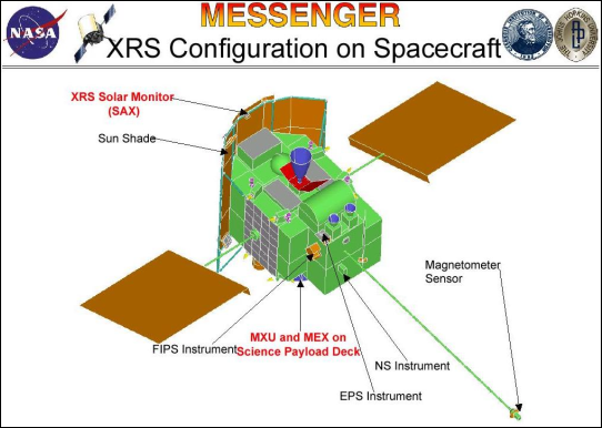
The XRS is comprised of three physical units. The GPCs make up the Mercury X-ray Unit (MXU). The Solar Assembly for X-rays (SAX) includes the Si-PIN diode, preamplifier, shaping electronics and thermal electric cooler (TEC). The analog and digital electronics are contained in the Main Electronics for X-rays (MEX) unit. The SAX is located at the “top center” edge of the solar shield (see Figure 1). The MXU and MEX are co-located within the payload adapter ring.
Figure 1 XRS Configuration on MESSENGER
This SIS document only contains information on the XRS Experiment Data Record (EDR) data product. Please refer to the Calibrated Data Record (CDR) SIS and Reduced Data Record (RDR) SIS for documentation on higher level XRS products.
There are two data products for the XRS EDR archive. One is the MESSENGER X-Ray Spectrometer EDR. This is the primary data product. The other is the XRS Command Echo EDR. This document will refer to the two types by their standard data product id. “XRSEDR” for the XRS spectral data and “XRS COMMAND ECHO” for the command echo data. Each EDR product consists of 2 files. One file contains the data itself. The XRSEDR data are arranged in binary table format while the XRS COMMAND ECHO data are stored in ASCII table format. The other file is a label file, which describes the content of the data file. The label file defines the start time and end of the observation, product creation time, etc. The PDS label file contains a reference pointer to a separate format file. The format file describes the structure of the table in the data file and each of the different fields within the table. This format file resides in LABEL directory of the data archive volume. Each EDR data product will contain all observations collected or command echos generated by the instrument on a given Earth day.
There will be one XRS EDR data volume archive. The volume archive will contain CODMAC (Committee on Data Management and Computation) level 2 data products, also known as EDRs. Each product will have a unique file name and conform to the file naming convention in section 6.3. All EDR products will be stored at the APL Science Operations Center (SOC). Data downlink is telemetered through NASA’s Deep Space Network (DSN) managed by the Jet Propulsion Laboratory in Pasadena, CA, and then forwarded to the APL Mission Operations Center (MOC). The MOC then sends telemetry in the form of CCSDS packets to the SOC. Level 1 CODMAC XRS data is extracted from the CCSDS packets and stored in a database and file system at the SOC. Periodic automatic execution of the ‘PIPE-XRS2EDR’ software will then generate the EDRs.
The X-Ray Spectrometer EDR files will be produced by the MESSENGER Science Operations Center (SOC) operated jointly by APL and ACT. The ‘PIPE-XRS2EDR’ software creates EDR data in the PDS labeled format specified by this SIS. The EDR data products are made available to the MESSENGER Science Team for initial evaluation and validation. At the end of the evaluation and validation period, the data are organized and stored in the directory structure described in section 6.5 for transmittal to the PDS Geosciences node. The transmittal process is described in the following section, Data Flow. The initial and subsequent releases to PDS are according to the schedule table in the MESSENGER Data Management and Archiving Plan. PDS will then provide public access to the data products via its online distribution system.
The MESSENGER SOC operates under the auspices of the MESSENGER Project Scientist to plan data acquisition and generate and validate data archives. The SOC supports and works with the MOC, The Science Team, instrument scientists, and the PDS.
Figure 2 MESSENGER Data Flow shows the flow of data within the MESSENGER project and out to PDS. The MOC handles raw data flow to and from the MESSENGER spacecraft and the SOC converts the raw telemetry into EDRs. The Science Team validates the EDRs and notifies the SOC if corrections are needed. Documentation and EDRs are delivered to the PDS Geosciences node. SPICE Kernels are delivered to the PDS Navigation and Ancillary Information (NAIF) node.
The MESSENGER SOC will deliver data for the XRS EDR data volume in standard product packages. Each package will comprise data and ancillary data files, organized into directory structures consistent with the volume design described in section 6.5.
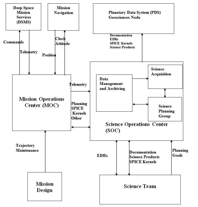
Figure 2 MESSENGER Data Flow
The following describes the electronic transfer process of releasing data to PDS for the first PDS delivery. Future data deliveries will be assumed to follow the same process unless otherwise noted in an update of this document. Given the long duration of the mission the project is reserving the option of exploring alternate data delivery methods for subsequent deliveries. As such, the method of electronic transfer may change and will be revised accordingly in the SIS. Any changes to the delivery process will be noted in an update to the SIS document and will include the specific dates which will use the new delivery process. The delivery of products to the data volume will follow the schedule in the MESSENGER Data Management and Archiving Plan
In the week prior to the delivery date the directory structure will be compressed into a single “zip archive” file for transmittal to the PDS node. The zip archive preserves the directory structure internally so that it can be recreated after electronic delivery to the PDS node. The zip archive file is transmitted to the PDS node via FTP to an account set up by the receiving node. Also transmitted will be a checksum file created using the MD5 algorithm. This provides an independent method of verifying the integrity of the zip file after it has been sent. Within days of transmittal the PDS node will acknowledge receipt of the archive and checksum file. If acknowledgement is not received, or if problems are reported, the MESSENGER SOC will immediately take corrective action to effect successful transmittal.
After transmittal the PDS node will uncompress the zip archive file and check for data integrity using the checksum file. The node will then perform any additional verification and validation of the data provided and will report any discrepancies or problems to the MESSENGER SOC. It is expected that the node will perform these checks in about two weeks. After inspection has been completed to the satisfaction of the PDS node, the node will issue to the MESSENGER SOC acknowledgement of successful receipt of the data.
Following receipt of a data delivery the PDS node will organize the data into a PDS volume archive structure within its online data system. Newly delivered data will be made available publicly from PDS once accompanying labels and other documentation have been validated.
For every X-Ray data file there exists a PDS Label file. The label file conforms to PDS version 3.6 standards. Consult the PDS Standards Reference Document for more information on this standard. The PDS label describes the data product and provides ancillary information about the data product. The label file is detached and separate from the data file which contains the data in a PDS binary table. The following is an example of the contents of the XRSEDR PDS label file. Details about the label format are specified later in section 6.4.
PDS_VERSION_ID = "PDS3"
/*** FILE FORMAT ***/
FILE_RECORDS = 130
RECORD_TYPE = FIXED_LENGTH
RECORD_BYTES = 2258
/*** GENERAL DATA DESCRIPTION PARAMETERS ***/
PRODUCT_ID =
"XRS2006018_DAT"
PRODUCT_VERSION_ID = "V1"
PRODUCT_CREATION_TIME = 2006-08-30T21:26:05
PRODUCT_TYPE = "DATA"
STANDARD_DATA_PRODUCT_ID = "XRSEDR"
SOFTWARE_NAME = "PIPE-XRS2EDR"
SOFTWARE_VERSION_ID = "1.0"
INSTRUMENT_HOST_NAME = "MESSENGER"
INSTRUMENT_NAME = "XRAY SPECTROMETER"
INSTRUMENT_ID = "XRS"
DATA_SET_ID = "MESS-E/V/H-XRS-2-EDR-RAWDATA-V1.0"
MISSION_PHASE_NAME = "VENUS 1 CRUISE"
TARGET_NAME = "CALIBRATION"
START_TIME = 2006-01-18T13:13:57
STOP_TIME = 2006-01-18T23:58:56
SPACECRAFT_CLOCK_START_COUNT = "46077252"
SPACECRAFT_CLOCK_STOP_COUNT = "46115952"
^TABLE =
"XRS2006018.DAT"
OBJECT = TABLE
COLUMNS = 175
INTERCHANGE_FORMAT = BINARY
ROW_BYTES = 2258
ROWS = 130
DESCRIPTION = "
This table
contains X-ray spectra and associated instrument
parameters, as observed by the MESSENGER X-Ray Spectrometer (XRS).
Detailed
descriptions for the parameters defined below are contained
in the EDR
SIS document.
The
complete column definitions are contained in an external file
found in
the LABEL directory of the archive volume.
"
^STRUCTURE = "XCOLUMN.FMT"
END_OBJECT = TABLE
END
Notice that the external format file, “XCOLUMN.FMT”, defines the structure of the binary table. The table structure is detailed in APPENDIX: XCOLUMN.FMT File.
The following is an example of the XRS Command Echo label file.
PDS_VERSION_ID = "PDS3"
/*** FILE FORMAT ***/
FILE_RECORDS = 20
RECORD_TYPE = FIXED_LENGTH
RECORD_BYTES = 125
/*** GENERAL DATA DESCRIPTION PARAMETERS ***/
PRODUCT_ID = "XRS_CMD2009274_TAB"
PRODUCT_VERSION_ID = "V1"
PRODUCT_CREATION_TIME = 2009-10-01T20:47:23
PRODUCT_TYPE = "ANCILLARY"
STANDARD_DATA_PRODUCT_ID = "XRS_COMMAND_ECHO"
SOFTWARE_NAME = "PIPE-XRS2EDR"
SOFTWARE_VERSION_ID = "1.1"
INSTRUMENT_HOST_NAME = "MESSENGER"
INSTRUMENT_NAME = "XRAY SPECTROMETER"
INSTRUMENT_ID = "XRS"
DATA_SET_ID =
"MESS-E/V/H-XRS-2-EDR-RAWDATA-V1.0"
MISSION_PHASE_NAME = "MERCURY 3 FLYBY"
TARGET_NAME = "MERCURY"
START_TIME = 2009-10-01T13:09:18
STOP_TIME = 2009-10-01T13:10:58
SPACECRAFT_CLOCK_START_COUNT = 162890024
SPACECRAFT_CLOCK_STOP_COUNT = 162890124
^TABLE =
"XRS_CMD2009274.TAB"
OBJECT = TABLE
COLUMNS = 7
INTERCHANGE_FORMAT = ASCII
ROW_BYTES = 125
ROWS = 20
DESCRIPTION = "
This table
contains one set of the commands executed by the MESSENGER
X-Ray
Spectrometer (XRS). A set is defined as all data with timestamps
corresponding to a given Earth day. The complete column definitions are
contained
in an external structure file found in the LABEL directory of
the
archive volume. Additional details are contained in the EDR SIS
document.
"
^STRUCTURE = "XRS_CMDECHO.FMT"
END_OBJECT = TABLE
END
Notice that the external format file, “XRS_CMDECHO.FMT”, defines the structure of the ASCII table. The table structure is detailed in APPENDIX: XRS_CMDECHO.FMT file.
The XRS EDR data products comply with the Planetary Data System standards for file formats and labels, as specified in the PDS Standards Reference. The EDR data products include:
·
a pointer to a FORMAT file which describes the structure of
the table
The MET field in the XRS EDR binary table matches the spacecraft time in integer seconds that is transmitted to MESSENGER subsystems by the Integrated Electronics Module (IEM). This is referred to by the MESSENGER project as Mission Elapsed Time (MET). MET = 0 is August 3, 2004, at 05:59:16 UTC, which is 1000 seconds prior to the MESSENGER launch. Relativistic effects and circumstances occurring during the mission would result in MET not being a true account of seconds since launch. Following a planned spacecraft clock reset[1] on January 8, 2013, partition numbers (1/, or 2/) were added to product labels to disambiguate MET seconds after the spacecraft clock reset (if partition number is not present, SPICE defaults to partition 1/). For this reason the MESSENGER spacecraft clock coefficients file is archived at the PDS Navigation and Ancillary Information Facility (NAIF) Node. This file is used in conjunction with the leapseconds kernel file in order to calculate the conversion between MET and UTC.
The conversion is easily done through the use of SPICE kernels and the CHRONOS Utility. CHRONOS is a utility included with the SPICE package that is distributed by the PDS NAIF node. The SPICE kernels are files that contain the information needed to perform the conversion. Two SPICE kernels are required. One is the Leapseconds Kernel (LSK) and the other is the MESSENGER Spacecraft Clock Kernel (SCLK). The SCLK file is used by CHRONOS to convert between spacecraft clock time and ephemeris time, while the LSK file is used to convert from ephemeris time to UTC time. The CHRONOS utility is self-documenting and the SPICE package itself contains full documentation on each of the utilities (including CHRONOS) and how they are used.
The following lists the computational assumptions for the geometric and viewing data provided in the PDS label. There are two coordinate systems in use: 1) the celestial reference system used for target and spacecraft position and velocity vectors, and camera pointing; and 2) the planetary coordinate system for geometry vectors and target location. The celestial coordinate system is J2000 (Mean of Earth equator and equinox of J2000). The planetary coordinate system is planetocentric.
COMPUTATIONAL ASSUMPTIONS
·
The
mid-point time of observation is used for the geometric element computations.
·
Label
parameters reflect observed, not true, geometry. Therefore light-time and
stellar aberration corrections are used as appropriate.
·
The
intertial reference frame is J2000 (also called EME2000).
·
Latitudes
and longitudes are planetocentric.
·
Distances
are in km, speeds are in km/sec, angles are in degrees, angular rates are in
degrees/sec, unless otherwise noted.
·
Angle
ranges are 0 to 360 degrees for azimuths and local hour angle.
Longitudes range from 0 to 360 degrees (positive to
the East). Latitudes range from –90 to 90 degrees.
The data are organized following PDS standards and stored on hard disk and in a SQL (Structured Query Language) database for rapid access during mission operations. The MESSENGER SOC will transfer data to PDS via electronic transfer and delivery methods as detailed in section 5.3.3. After verification of the data transfer PDS will provide public access to MESSENGER science data products through its online data distribution system.
The XRS EDR data products will be validated by the XRS Instrument scientist for science content and for compliance with PDS archive standards [MESSENGER Data Management and Archiving Plan].
The MESSENGER XRS EDR data set will be archived at the PDS Geosciences node as a data archive volume. The XRS EDR products in the data archive volume are intended to store the data in a form closest to the raw telemetry data received from the spacecraft. The automated production and release of the EDRs will follow the release schedule in the MESSENGER Data Management and Archiving Plan. If errors are discovered the data will be replaced with corrected EDRs on the next scheduled delivery date.
The possibility exists that errors may be introduced into the archive even with validation procedures applied to the archive volumes. An ERRATA report file is maintained to track and document all discovered uncorrectable errors that may occur during the mission. Correctable errors, such as revised EDRs or EDRs that were missing from a previous PDS delivery will be provided at the next scheduled PDS delivery or at the final delivery date (see schedule in the MESSENGER Data Management and Archiving Plan). PDS will then replace the outdated files with the revised EDR files in the data directories of the archive volume. The ERRATA report file is archived in the ROOT directory of the XRS EDR data volume.
The geometric elements are an essential part of the archive;
they contain the data and information to characterize the geometric properties
of the sensor, and to fully describe the viewing geometry of an observation. These data are essential to geodetic, cartographic, and
photometric applications.
The geometric elements are organized according to the SPICE kernel concepts adopted by the Navigational Ancillary Information Facility (NAIF) at the Jet Propulsion Laboratory. SPICE is an acronym for Spacecraft, Planet, Instrument, C-matrix, and Event kernels. The SPICE kernel data set will be stored in ancillary data volumes at the PDS NAIF Node.
Data is stored in binary table format. A detached PDS format file will provide a detailed description of the structure of the binary table.
The general form of the XRSEDR file name is "XRSYYYYDOY.DAT", where:
XRS instrument identifier: represents the XRS instrument
YYYY The four digit year corresponding to the MET for each record in the EDR.
DOY The three digit day of year corresponding to the MET for each record in the EDR.
.DAT the file extension will always be the
three character
mnemonic
‘DAT’, indicating data stored in binary format.
The PDS label will have the same naming convention but with the file extension .LBL.
The command echo EDRs will have a separate file naming convention to distinguish themselves from the science data. The general form of the XRS Command Echo EDRs is “XRS_CMDYYYYDOY.TAB” where:
XRS_CMD indicates the file contains XRS command echo data.
YYYY The four digit year corresponding to the MET for each record in the EDR.
DOY The three digit day of year corresponding to the MET for each record in the EDR.
.TAB the file extension indicating the data
is stored in ASCII format.
The following are the keyword definitions for the detached PDS label file. The detached PDS label file has the same name as the data file it describes, except for the extension .LBL to distinguish it as a label file.
PDS_VERSION_ID
Represents the version number of the PDS standards documents that is valid when a data product label is created. PDS3 is used for the Messenger Data products.
FILE_RECORDS
The file_records element indicates the number of physical file records, including both label records and data records.
RECORD_TYPE
The record_type element indicates the record format of a file. The FIXED_LENGTH value is appropriate for the BINARY table object used for the MESSENGER XRS EDR data products.
RECORD_BYTES
This element indicates the number of bytes in a physical file record, including record terminators and separators.
PRODUCT_ID
The product_id data element represents a permanent, unique identifier assigned to a data product by its producer. See also: source_product_id.
Note: In the PDS, the value assigned to product_id must be unique within its data set.
PRODUCT_VERSION_ID
Identifies the version of the product, represented initially by “V1”. The version number will be incremented if the product needs to be regenerated as a result of a correction of the data or as a result of a change in the method used to create the product.
PRODUCT_CREATION_TIME
Stores the time that the data product was created, in UTC time.
PRODUCT_TYPE
The XRS EDR contains science data, hence the value is always “DATA”.
STANDARD_DATA_PRODUCT_ID
The XRS EDR files are identified as belonging to the same standard data product via this ID.
SOFTWARE_NAME
Identifies the name of the software system creating the data products.
SOFTWARE_VERSION_ID
The version number of program or program library used by the instrument to collect observations.
INSTRUMENT_HOST_NAME
Identifies the MESSENGER spacecraft on which the instrument is located.
INSTRUMENT_NAME
The full, unabbreviated name of the instrument.
INSTRUMENT_ID
The project abbreviation of the instrument.
DATA_SET_ID
Uniquely identifies the EDR file as part of a volume collection.
MISSION_PHASE_NAME
Identifies the project designation of the mission phase associated with the data product.
TARGET_NAME
The target of the observation.
START_TIME
The start time of the observation.
STOP_TIME
The time when the instrument stopped collecting measurements.
SPACECRAFT_CLOCK_START_COUNT
Clock count of the spacecraft computer at the start of the observation.
SPACECRAFT_CLOCK_STOP_COUNT
Clock count of the spacecraft computer at the end of the observation.
^TABLE
Identifies the name of the EDR file which contains the data in BINARY table format. The structure of the data file is defined in a referenced format file.
^STRUCTURE
This is a pointer to the external file which provides the structure definition for the table object.
Each XRS PDS label will contain a pointer to the XCOLUMN.FMT file. This file describes the structure of the XRS binary table. This includes column name, byte size, data type, applicable units, and a description of the value assigned to the column. The full XCOLUMN.FMT file is shown in section 8.1 Appendix: XCOLUMN.FMT file.
Each XRS COMMAND ECHO PDS label will contain a pointer to the XRS_CMDECHO.FMT file. This file describes the structure of the XRS ASCII table. This includes column name, byte size, data type, applicable units, and a description of the value assigned to the column. The full XRS_CMDECHO.FMT file is shown in the Appendix.
The following describes the keywords used in the format files:
OBJECT
Identifies
the object as a column field within a binary table.
NAME
Indicates
a literal value representing the common term used to identify an element or
object. NOTE: in the PDS data dictionary, name is restricted to 30 characters
and must conform to PDS nomenclature standards.
COLUMN_NUMBER
Identifies
the location of the column within the larger table data object. For tables
consisting of rows (I= 1, N) and columns (j = 1, M) the column_number is the
j-th index of any row.
BYTES
Specifies
the total number of bytes allocated for this particular column element.
DATA_TYPE
Specifies
the internal representation and/or mathematical properties of the value being
stored in this column.
START_BYTE
Identifies
the location of the first byte of the particular column, counting from 1.
DESCRIPTION
Describes
the value(s) stored in the column object.
ITEMS
This
keyword is used for columns containing spectra values, such as column 175 in
the XRS EDR binary table. Defines the number of multiple, identical occurrences
of a single data item. For example, in column 175 there are 244 items which
correspond to channels 10-253 in the detector.
ITEM_BYTES
This
keyword is used for columns containing spectra values, such as column 175 in
the XRS EDR binary table. Represents the size of each individual item within
the column field. For example, in column 175 each item is a 2-byte integer.
The following illustration shows the directory structure overview for the XRS EDR Data Archive Volume. This volume contains the XRS EDR data products, supporting documentation, and any additional files required for the volume to be compliant with PDS standards. The content of the volume is expected to be updated with periodic releases according to the schedule in the MESSENGER Data Management and Archiving Plan. Revised EDRs (if needed) will also be delivered according to the same schedule. Revised EDRs will have an incremented version number in the PDS label.
Directory Structure Overview
<ROOT>
___________________________________|____________________
|
| | | | |
<DATA> <LABEL> <INDEX> <CATALOG> <GEOMETRY> <DOCUMENT>
|
|_____________________________________
| | |
<EARTH
CRUISE> <EARTH FLYBY> <..CONTINUE WITH MISSION PHASES>
|___________
|
|
<2004> <2005>
|_______________
| | |
<SEP> <OCT> <NOV>
<ROOT> Directory
This is the top-level directory of the data volume. The following are files contained in the root dirctory.
AAREADME.TXT - General information file. Provides users with information about the MESSENGER XRS data products. Directs user to other documents on the volume containing more detailed information.
VOLDESC.CAT - PDS file containing the VOLUME object. This gives a high-level description of the contents of the volume. Information includes: production date, producer name and institution, volume ID, etc.
ERRATA.TXT - Text file for identifying and describing errors and/or anomalies found in the current volume, and possibly previous volumes of a set. Any known errors for the associated volume will be documented in this file. This includes revised EDRs meant to replace EDRs in a previous PDS delivery.
<DOCUMENT>
Directory
This subdirectory contains the documentation that will be needed in order to understand and analyze the EDR data products. Multiple copies of each document will be stored, each one in a different format. Files will be stored in PDF, ASCII, and HTMLformat.
DOCINFO.TXT – Identifies and describes the function of each file in the DOCUMENT directory.
<CATALOG> Directory
This
subdirectory contains the catalog object files for the entire volume. The
following files are included in the catalog subdirectory.
CATINFO.TXT: Identifies and describes the
function of each file in the catalog directory.
DATASET.CAT: Describes the general content of
the data set and includes information about the duration of the mission and the
person or group responsible for producing the data.
INSTRUMENT.CAT: Describes physical attributes of
the XRS instrument and provides relevant references to published literature.
INSTRUMENT_HOST.CAT: Describes the MESSENGER
spacecraft.
MISSION.CAT: Describes the scientific goals
and objectives of the MESSENGER program. It also identifies key people and
institutions.
PERSON.CAT: Lists key XRS instrument personnel
and their contact information.
REF.CAT: Contains full references for
citations given in other documents.
<INDEX> Directory
This
subdirectory contains the indices for the XRS EDR data products. The following files are contained in the
index subdirectory.
INDXINFO.TXT – Identifies and describes the
function of each file in the index subdirectory. This includes a description of the structure
and contents of each index table in the subdirectory AND usage notes.
INDEX.TAB - The EDR index file is organized
as a table: there
is
one entry for each of the data files included in the XRS data set; the columns
contain parameters that describe the observation as well as instrument and
spacecraft parameters.
INDEX.LBL - Detached PDS label for INDEX.TAB.
MD5.TAB: Contains MD5 checksums for all
files in the archive volume.
MD5.LBL: Detached PDS label for the
MD5.TAB file.
<LABEL>
Directory
This subdirectory contains format files referenced
in the EDR PDS labels.
XCOLUMN.FMT: The format file that describes the binary Table
object which stores the data in the XRS EDR.
XRS_CMDECHO.FMT: The format file that describes the text Table
object which stores the command echo EDRs.
<Geometry>
Directory
This subdirectory contains information about the
SPICE kernel files needed to determine the observation geometry for the data.
GEOMETRY.TXT : Identifies and describes the SPICE kernels that a user must have in order to determine observation geometry for the data. The SPICE kernel files are archived with the PDS NAIF node.
<DATA>
- Data Directory
This is the top level directory containing the EDRs. The data directories are organized by mission phase, followed by year, and month in UTC. The EDRs are contained in the month folders.
The MESSENGER XRS EDR archive will be transferred from the SOC to the Planetary Data System Geosciences Node using the electronic transfer process detailed in section 5.3.3. The transfer will take place according to the schedule in the MESSENGER Data Management and Archiving Plan.
Table 1. Schedule of Data Releases by Mission Phase – REMOVED – refer to release schedule in MESSENGER Data Management and Archiving Plan.
The following is the full content of the XCOLUMN.FMT file. This file describes the binary table fields that will be contained in the XRSEDR binary table along with the byte size, data type, and a brief description of each field.
/* Table
Structure for XRS EDRs */
NOTE =
"An XRS flight software upload was implemented on 2007-08-17 UTC
which affects COLUMN 40 of the XRS EDR binary
table. Prior to 2007-08-17,
column 40 was named LVPS_SPARE2 and was a
spare, unused data column. On
and after 2007-08-17 the column is used to
indicate the SAX_TEMP_MODE."
OBJECT =
COLUMN
NAME = MET
COLUMN_NUMBER = 1
BYTES = 4
DATA_TYPE = MSB_UNSIGNED_INTEGER
START_BYTE = 1
DESCRIPTION = "Time tag in seconds."
END_OBJECT = COLUMN
OBJECT = COLUMN
NAME = ORBIT_NUMBER
COLUMN_NUMBER = 2
BYTES = 4
DATA_TYPE = MSB_UNSIGNED_INTEGER
START_BYTE = 5
DESCRIPTION = "Orbit number is a unique identifier
for a given
orbit of the MESSENGER spacecraft around
Mercury. Orbit number is
defined as starting at apoherm and is
calculated using the MET value
and the appropriate SPICE kernels. Orbit
numbering does not start
until MESSENGER performs the Mercury orbit
insertion. Until that time
the value for orbit number is 0."
END_OBJECT = COLUMN
OBJECT = COLUMN
NAME = STATUS_INTERVAL
COLUMN_NUMBER = 3
BYTES = 2
DATA_TYPE = MSB_UNSIGNED_INTEGER
START_BYTE = 9
DESCRIPTION = "Time period (in seconds) between
status packets."
END_OBJECT = COLUMN
OBJECT = COLUMN
NAME = SC_RANGE
COLUMN_NUMBER = 4
BYTES = 2
DATA_TYPE = MSB_UNSIGNED_INTEGER
START_BYTE = 11
DESCRIPTION = "+Z range to Mercury surface. =65535
N/A."
END_OBJECT = COLUMN
OBJECT = COLUMN
NAME
= SC_ANGLE
COLUMN_NUMBER = 5
BYTES = 2
DATA_TYPE = MSB_UNSIGNED_INTEGER
START_BYTE = 13
DESCRIPTION = "+Z angle to Mercury surface. =65535
N/A."
END_OBJECT = COLUMN
OBJECT = COLUMN
NAME = DATA_QUALITY
COLUMN_NUMBER = 6
BYTES = 4
DATA_TYPE = MSB_UNSIGNED_INTEGER
START_BYTE = 15
DESCRIPTION = "Integer representation of a 32-bit
array. Each bit
represents a data quality flag. Currently
only the least
significant bit is being used. Other bit
positions will be
designated during the course of the
mission as more data quality
parameters are identified by the
instrument team. =1, the actual
data length in bytes does not match the
reported length. =0, actual
data length in bytes matches reported
length."
END_OBJECT = COLUMN
OBJECT = COLUMN
NAME = SW_VERSION
COLUMN_NUMBER = 7
BYTES = 1
DATA_TYPE = MSB_UNSIGNED_INTEGER
START_BYTE = 19
DESCRIPTION = "Software version number."
END_OBJECT = COLUMN
OBJECT = COLUMN
NAME = ALARM_ID
COLUMN_NUMBER = 8
BYTES = 1
DATA_TYPE = MSB_UNSIGNED_INTEGER
START_BYTE = 20
DESCRIPTION = "Latest alarm ID."
END_OBJECT = COLUMN
OBJECT = COLUMN
NAME
= ALARM_TYPE
COLUMN_NUMBER = 9
BYTES = 1
DATA_TYPE = MSB_UNSIGNED_INTEGER
START_BYTE = 21
DESCRIPTION = "Latest alarm type. =0 persistent,
=1 transient."
END_OBJECT = COLUMN
OBJECT = COLUMN
NAME = ALARM_COUNT
COLUMN_NUMBER = 10
BYTES = 1
DATA_TYPE = MSB_UNSIGNED_INTEGER
START_BYTE = 22
DESCRIPTION = "Count of number of
alarms."
END_OBJECT = COLUMN
OBJECT = COLUMN
NAME = CMD_EXECUTED
COLUMN_NUMBER = 11
BYTES = 1
DATA_TYPE = MSB_UNSIGNED_INTEGER
START_BYTE = 23
DESCRIPTION = "Number of commands
executed."
END_OBJECT = COLUMN
OBJECT = COLUMN
NAME = CMD_REJECTED
COLUMN_NUMBER = 12
BYTES = 1
DATA_TYPE = MSB_UNSIGNED_INTEGER
START_BYTE = 24
DESCRIPTION = "Number of commands rejected."
END_OBJECT = COLUMN
OBJECT = COLUMN
NAME = MONITOR_RESPONSE
COLUMN_NUMBER = 13
BYTES = 1
DATA_TYPE =
MSB_UNSIGNED_INTEGER
START_BYTE = 25
DESCRIPTION = "Monitor response. =0 disabled, =1
enabled."
END_OBJECT = COLUMN
OBJECT = COLUMN
NAME = MEM_WRITE_ENABLE
COLUMN_NUMBER = 14
BYTES = 1
DATA_TYPE = MSB_UNSIGNED_INTEGER
START_BYTE = 26
DESCRIPTION = "Memory write enable. =0 disabled,
=1 enabled."
END_OBJECT = COLUMN
OBJECT = COLUMN
NAME = MACRO_LEARN_MODE
COLUMN_NUMBER = 15
BYTES = 1
DATA_TYPE = MSB_UNSIGNED_INTEGER
START_BYTE = 27
DESCRIPTION = "Macro learn mode. =0 not learning,
=1 learning."
END_OBJECT = COLUMN
OBJECT = COLUMN
NAME = SPARE
COLUMN_NUMBER = 16
BYTES = 1
DATA_TYPE = MSB_UNSIGNED_INTEGER
START_BYTE = 28
DESCRIPTION = "Spare column for possible future
use."
END_OBJECT = COLUMN
OBJECT = COLUMN
NAME = SCIENCE_RECORD_VERSION
COLUMN_NUMBER = 17
BYTES = 1
DATA_TYPE = MSB_UNSIGNED_INTEGER
START_BYTE = 29
DESCRIPTION = "Version of science packet
format."
END_OBJECT = COLUMN
OBJECT = COLUMN
NAME
= MACRO_ID
COLUMN_NUMBER = 18
BYTES = 1
DATA_TYPE = MSB_UNSIGNED_INTEGER
START_BYTE = 30
DESCRIPTION = "ID of most recent macro
executed."
END_OBJECT = COLUMN
OBJECT = COLUMN
NAME = MACROS_REJECTED
COLUMN_NUMBER = 19
BYTES = 1
DATA_TYPE = MSB_UNSIGNED_INTEGER
START_BYTE = 31
DESCRIPTION = "Number of macro commands
rejected."
END_OBJECT = COLUMN
OBJECT = COLUMN
NAME = MACROS_EXECUTED
COLUMN_NUMBER = 20
BYTES = 1
DATA_TYPE = MSB_UNSIGNED_INTEGER
START_BYTE = 32
DESCRIPTION = "Number of macro commands
executed."
END_OBJECT = COLUMN
OBJECT = COLUMN
NAME = MACRO_BLOCKS
COLUMN_NUMBER = 21
BYTES = 2
DATA_TYPE = MSB_UNSIGNED_INTEGER
START_BYTE = 33
DESCRIPTION = "Number of macro blocks
free."
END_OBJECT = COLUMN
OBJECT = COLUMN
NAME = GPC1_MG_SAFING_LEVEL
COLUMN_NUMBER = 22
BYTES = 1
DATA_TYPE
= MSB_UNSIGNED_INTEGER
START_BYTE = 35
DESCRIPTION = "The safing level set for the
GPC1-MG detector.
=0 level zero or nominal level safing; the
software will monitor the
planetary detector for the conditions which
necessitate a higher
level of safing.
=1 level 1 safing; the HVPS voltage level
for the affected sensor is
ramped down to 0 at a rate of 100
V/sec.
=2 level 2 safing; the software turns off
analog power to the
affected sensor and turns off the
associated HVPS. No further
attempts are made to restore the
level-two-safed sensor to nominal
safing.
The software waits for ground command to reset the affected
HVPS voltage levels."
END_OBJECT = COLUMN
OBJECT = COLUMN
NAME = GPC1_MG_SAFING_RETRY
COLUMN_NUMBER = 23
BYTES = 1
DATA_TYPE = MSB_UNSIGNED_INTEGER
START_BYTE = 36
DESCRIPTION = "The max number of retry attempts to
reset the
GPC1-MG detector to level 0
safing."
END_OBJECT = COLUMN
OBJECT = COLUMN
NAME = GPC2_AL_SAFING_LEVEL
COLUMN_NUMBER = 24
BYTES = 1
DATA_TYPE
= MSB_UNSIGNED_INTEGER
START_BYTE = 37
DESCRIPTION = "The safing level set for the
GPC2-AL detector.
=0 level zero or nominal level safing; the
software will monitor the
planetary detector for the conditions which
necessitate a higher
level of safing.
=1 level 1 safing; the HVPS voltage level
for the affected sensor is
ramped down to 0 at a rate of 100
V/sec.
=2 level 2 safing; the software turns off
analog power to the
affected sensor and turns off the
associated HVPS. No further
attempts are made to restore the
level-two-safed sensor to nominal
safing.
The software waits for ground command to reset the affected
HVPS voltage levels."
END_OBJECT =
COLUMN
OBJECT = COLUMN
NAME = GPC2_AL_SAFING_RETRY
COLUMN_NUMBER = 25
BYTES = 1
DATA_TYPE = MSB_UNSIGNED_INTEGER
START_BYTE = 38
DESCRIPTION = "The max number of retry attempts to
reset the
GPC2-AL detector to level 0
safing."
END_OBJECT = COLUMN
OBJECT = COLUMN
NAME = GPC3_UN_SAFING_LEVEL
COLUMN_NUMBER = 26
BYTES = 1
DATA_TYPE = MSB_UNSIGNED_INTEGER
START_BYTE = 39
DESCRIPTION = "The safing level set for the
GPC3-UNfiltered (UN)
detector.
=0 level zero or nominal level safing; the
software will monitor the
planetary detector for the conditions which
necessitate a higher
level of safing.
=1 level 1 safing; the HVPS voltage level
for the affected sensor is
ramped down to 0 at a rate of 100
V/sec.
=2 level 2 safing; the software turns off
analog power to the
affected sensor and turns off the
associated HVPS. No further
attempts are made to restore the
level-two-safed sensor to nominal
safing.
The software waits for ground command to reset the affected
HVPS voltage levels."
END_OBJECT = COLUMN
OBJECT = COLUMN
NAME = GPC3_UN_SAFING_RETRY
COLUMN_NUMBER = 27
BYTES = 1
DATA_TYPE = MSB_UNSIGNED_INTEGER
START_BYTE = 40
DESCRIPTION = "The max number of retry attempts to
reset the
GPC3-UN detector to level 0
safing."
END_OBJECT = COLUMN
OBJECT = COLUMN
NAME = DISCARDED_PACKET_COUNTER
COLUMN_NUMBER = 28
BYTES = 1
DATA_TYPE = MSB_UNSIGNED_INTEGER
START_BYTE = 41
DESCRIPTION = "Number of calls to send-pkt that
resulted in a
return value of false."
END_OBJECT = COLUMN
OBJECT = COLUMN
NAME = TEC_LOSS_OF_CONTROL
COLUMN_NUMBER = 29
BYTES = 1
DATA_TYPE = MSB_UNSIGNED_INTEGER
START_BYTE = 42
DESCRIPTION = "TEC loss of control flag. =0 no
loss of control,
=1 loss of control."
END_OBJECT = COLUMN
OBJECT = COLUMN
NAME = SOLAR_FLARE_DETECTED
COLUMN_NUMBER = 30
BYTES = 1
DATA_TYPE = MSB_UNSIGNED_INTEGER
START_BYTE = 43
DESCRIPTION
= "Solar flare detection
flag. =0 no solar flare
detected, =1 flare detected."
END_OBJECT = COLUMN
OBJECT = COLUMN
NAME = FLARE_HANDLING_ENABLED
COLUMN_NUMBER = 31
BYTES = 1
DATA_TYPE = MSB_UNSIGNED_INTEGER
START_BYTE = 44
DESCRIPTION = "Solar flare handling enabled flag,
software checks
this value upon detection of a solar
flare. =0 do not handle solar
flare detection. =1 continue algorithm for handling solar
flare
detection (see
SOLAR_FLARE_ENACT)."
END_OBJECT = COLUMN
OBJECT = COLUMN
NAME = FLARE_HANDLING_ENACTED
COLUMN_NUMBER = 32
BYTES = 1
DATA_TYPE = MSB_UNSIGNED_INTEGER
START_BYTE = 45
DESCRIPTION = "Solar flare handling enacted flag.
Allows software
to determine if solar flare handling has
already been enacted or
whether this is a new detection of a solar
flare. Only checked if
solar flare handling has been enabled (see
previous field).
=0 the software sets it to true, starts the
sf-time-enactable-left
counter out at sf-max-time-enactable, sets
a flag telling the 1Hz
process to end the current integration and
reporting period
immediately, and returns control to the 1Hz
process.
=1 , the software decrements the
sf-time-enactable-left counter and
checks its value. If sf-time-enactable-left is still greater
than
0, the algorithm does nothing further. If sf-time-enactable-left
has reached 0, the algorithm starts the
sf-timeout-left counter out
at sf-timeout-period and sets the
sf-handling-enacted-now flag to
false."
END_OBJECT = COLUMN
OBJECT = COLUMN
NAME = SENSOR_CONFIG_CHANGED
COLUMN_NUMBER = 33
BYTES = 1
DATA_TYPE = MSB_UNSIGNED_INTEGER
START_BYTE = 46
DESCRIPTION = "Flag showing whether sensor
configuration has
changed. =0 no change, =1
change."
END_OBJECT = COLUMN
OBJECT = COLUMN
NAME = LVPS_PLUS_5V
COLUMN_NUMBER = 34
BYTES = 1
DATA_TYPE = MSB_UNSIGNED_INTEGER
START_BYTE = 47
DESCRIPTION = "LVPS +5 volt monitor."
END_OBJECT = COLUMN
OBJECT = COLUMN
NAME = LVPS_MINUS_5V
COLUMN_NUMBER = 35
BYTES = 1
DATA_TYPE = MSB_UNSIGNED_INTEGER
START_BYTE = 48
DESCRIPTION = "LVPS -5 volt monitor."
END_OBJECT = COLUMN
OBJECT = COLUMN
NAME = LVPS_PLUS_12V
COLUMN_NUMBER = 36
BYTES = 1
DATA_TYPE = MSB_UNSIGNED_INTEGER
START_BYTE = 49
DESCRIPTION = "LVPS +12 volt monitor."
END_OBJECT = COLUMN
OBJECT = COLUMN
NAME = LVPS_MINUS_12V
COLUMN_NUMBER = 37
BYTES = 1
DATA_TYPE = MSB_UNSIGNED_INTEGER
START_BYTE
= 50
DESCRIPTION = "LVPS -12 volt monitor."
END_OBJECT = COLUMN
OBJECT = COLUMN
NAME = LVPS_SPARE0
COLUMN_NUMBER = 38
BYTES = 1
DATA_TYPE = MSB_UNSIGNED_INTEGER
START_BYTE = 51
DESCRIPTION = "Spare unused column for LVPS
monitoring."
END_OBJECT = COLUMN
OBJECT = COLUMN
NAME = LVPS_SPARE1
COLUMN_NUMBER = 39
BYTES = 1
DATA_TYPE = MSB_UNSIGNED_INTEGER
START_BYTE = 52
DESCRIPTION = "Spare unused column for LVPS monitoring."
END_OBJECT = COLUMN
OBJECT = COLUMN
NAME = SAX_TEMP_MODE
COLUMN_NUMBER = 40
BYTES = 1
DATA_TYPE = MSB_UNSIGNED_INTEGER
START_BYTE = 53
DESCRIPTION = "SAX Warmer temperature control
mode.
=0 SAX off, =1 SAX on, =2 SAX Software
Control."
END_OBJECT = COLUMN
OBJECT = COLUMN
NAME = SOFTWARE_SUB_VERSION
COLUMN_NUMBER = 41
BYTES = 1
DATA_TYPE = MSB_UNSIGNED_INTEGER
START_BYTE = 54
DESCRIPTION = "Sub-version of flight
software."
END_OBJECT = COLUMN
OBJECT = COLUMN
NAME = I2C_BUS_ERROR_COUNT
COLUMN_NUMBER = 42
BYTES = 1
DATA_TYPE = MSB_UNSIGNED_INTEGER
START_BYTE = 55
DESCRIPTION = "I2C bus error count."
END_OBJECT = COLUMN
OBJECT = COLUMN
NAME = LVPS_PLUS_5_I
COLUMN_NUMBER = 43
BYTES = 1
DATA_TYPE = MSB_UNSIGNED_INTEGER
START_BYTE = 56
DESCRIPTION = "LVPS +5V current."
END_OBJECT = COLUMN
OBJECT = COLUMN
NAME = LVPS_MINUS_5_I
COLUMN_NUMBER = 44
BYTES = 1
DATA_TYPE = MSB_UNSIGNED_INTEGER
START_BYTE = 57
DESCRIPTION
= "LVPS -5V current."
END_OBJECT = COLUMN
OBJECT = COLUMN
NAME = LVPS_PLUS_12_I
COLUMN_NUMBER = 45
BYTES = 1
DATA_TYPE = MSB_UNSIGNED_INTEGER
START_BYTE = 58
DESCRIPTION = "LVPS +12V current."
END_OBJECT = COLUMN
OBJECT = COLUMN
NAME = LVPS_MINUS_12_I
COLUMN_NUMBER = 46
BYTES = 1
DATA_TYPE = MSB_UNSIGNED_INTEGER
START_BYTE = 59
DESCRIPTION = "LVPS -12V current."
END_OBJECT = COLUMN
OBJECT = COLUMN
NAME = LVPS_TEMP
COLUMN_NUMBER = 47
BYTES = 1
DATA_TYPE = MSB_UNSIGNED_INTEGER
START_BYTE = 60
DESCRIPTION = "LVPS temperature."
END_OBJECT = COLUMN
OBJECT = COLUMN
NAME = LVPS_PRIMARY_I
COLUMN_NUMBER = 48
BYTES = 1
DATA_TYPE = MSB_UNSIGNED_INTEGER
START_BYTE = 61
DESCRIPTION = "LVPS primary current."
END_OBJECT = COLUMN
OBJECT = COLUMN
NAME = LVPS_SWITCHED_PRIMARY_I
COLUMN_NUMBER = 49
BYTES
= 1
DATA_TYPE = MSB_UNSIGNED_INTEGER
START_BYTE = 62
DESCRIPTION = "LVPS switched primary
current."
END_OBJECT = COLUMN
OBJECT = COLUMN
NAME = GPC1_MG_PLUS_5V
COLUMN_NUMBER = 50
BYTES = 1
DATA_TYPE = MSB_UNSIGNED_INTEGER
START_BYTE = 63
DESCRIPTION = "GPC1-MG +5 volt monitor."
END_OBJECT = COLUMN
OBJECT = COLUMN
NAME = GPC2_AL_PLUS_5V
COLUMN_NUMBER = 51
BYTES = 1
DATA_TYPE = MSB_UNSIGNED_INTEGER
START_BYTE = 64
DESCRIPTION = "GPC2-AL +5 volt monitor."
END_OBJECT = COLUMN
OBJECT = COLUMN
NAME = GPC3_UN_PLUS_5V
COLUMN_NUMBER = 52
BYTES = 1
DATA_TYPE = MSB_UNSIGNED_INTEGER
START_BYTE = 65
DESCRIPTION = "GPC3-UN +5 volt monitor."
END_OBJECT = COLUMN
OBJECT = COLUMN
NAME = SAX_PLUS_5V
COLUMN_NUMBER = 53
BYTES = 1
DATA_TYPE = MSB_UNSIGNED_INTEGER
START_BYTE = 66
DESCRIPTION = "SAX +5 volt monitor."
END_OBJECT = COLUMN
OBJECT = COLUMN
NAME = ANALOG_PLUS_5V
COLUMN_NUMBER = 54
BYTES = 1
DATA_TYPE = MSB_UNSIGNED_INTEGER
START_BYTE = 67
DESCRIPTION = "Analog +5 volt monitor."
END_OBJECT = COLUMN
OBJECT = COLUMN
NAME = DIGITAL_PLUS_5V
COLUMN_NUMBER = 55
BYTES = 1
DATA_TYPE = MSB_UNSIGNED_INTEGER
START_BYTE = 68
DESCRIPTION = "Digital +5 volt monitor."
END_OBJECT = COLUMN
OBJECT = COLUMN
NAME = GPC1_MG_MINUS_5V
COLUMN_NUMBER = 56
BYTES = 1
DATA_TYPE = MSB_UNSIGNED_INTEGER
START_BYTE = 69
DESCRIPTION = "GPC1-MG -5 volt monitor."
END_OBJECT = COLUMN
OBJECT = COLUMN
NAME = GPC2_AL_MINUS_5V
COLUMN_NUMBER = 57
BYTES = 1
DATA_TYPE = MSB_UNSIGNED_INTEGER
START_BYTE = 70
DESCRIPTION = "GPC2-AL -5 volt monitor."
END_OBJECT = COLUMN
OBJECT = COLUMN
NAME = GPC3_UN_MINUS_5V
COLUMN_NUMBER = 58
BYTES
= 1
DATA_TYPE = MSB_UNSIGNED_INTEGER
START_BYTE = 71
DESCRIPTION = "GPC3-UN -5 volt monitor."
END_OBJECT = COLUMN
OBJECT = COLUMN
NAME = SAX_MINUS_5V
COLUMN_NUMBER = 59
BYTES = 1
DATA_TYPE = MSB_UNSIGNED_INTEGER
START_BYTE = 72
DESCRIPTION = "SAX -5 volt monitor."
END_OBJECT = COLUMN
OBJECT = COLUMN
NAME = ANALOG_MINUS_5V
COLUMN_NUMBER = 60
BYTES = 1
DATA_TYPE = MSB_UNSIGNED_INTEGER
START_BYTE = 73
DESCRIPTION = "Analog -5 volt monitor."
END_OBJECT = COLUMN
OBJECT = COLUMN
NAME = TEC_I
COLUMN_NUMBER = 61
BYTES = 1
DATA_TYPE = MSB_UNSIGNED_INTEGER
START_BYTE = 74
DESCRIPTION = "TEC current."
END_OBJECT = COLUMN
OBJECT = COLUMN
NAME = MXU_TEMP
COLUMN_NUMBER = 62
BYTES = 1
DATA_TYPE = MSB_UNSIGNED_INTEGER
START_BYTE = 75
DESCRIPTION = "MXU temperature."
END_OBJECT = COLUMN
OBJECT = COLUMN
NAME = SOLAR_DETECTOR_TEMP
COLUMN_NUMBER = 63
BYTES = 1
DATA_TYPE = MSB_UNSIGNED_INTEGER
START_BYTE = 76
DESCRIPTION = "Solar detector
temperature."
END_OBJECT = COLUMN
OBJECT = COLUMN
NAME = SAX_TEMP
COLUMN_NUMBER = 64
BYTES = 1
DATA_TYPE = MSB_UNSIGNED_INTEGER
START_BYTE = 77
DESCRIPTION = "SAX temperature."
END_OBJECT = COLUMN
OBJECT = COLUMN
NAME = SOLAR_DETECTOR_I
COLUMN_NUMBER = 65
BYTES = 1
DATA_TYPE = MSB_UNSIGNED_INTEGER
START_BYTE = 78
DESCRIPTION = "Solar detector current."
END_OBJECT = COLUMN
OBJECT = COLUMN
NAME = GPC1_MG_VOLTAGE_STEPPING
COLUMN_NUMBER = 66
BYTES = 1
DATA_TYPE = MSB_UNSIGNED_INTEGER
START_BYTE = 79
DESCRIPTION = "Indicates whether the GPC1-MG
detector's high
voltage state is seeking. See the MESSENGER
XRS Software
Specification document for an explanation
of the seeking state. =0
no, =1 yes."
END_OBJECT = COLUMN
OBJECT = COLUMN
NAME = GPC1_MG_VOLTAGE
COLUMN_NUMBER = 67
BYTES = 2
DATA_TYPE = MSB_UNSIGNED_INTEGER
START_BYTE = 80
DESCRIPTION = "GPC1-MG voltage
measurement."
END_OBJECT = COLUMN
OBJECT = COLUMN
NAME = GPC2_AL_VOLTAGE_STEPPING
COLUMN_NUMBER = 68
BYTES = 1
DATA_TYPE = MSB_UNSIGNED_INTEGER
START_BYTE = 82
DESCRIPTION = "Indicates whether the GPC2-AL
detector's high
voltage state is seeking. See the MESSENGER
XRS Software
Specification document for an explanation
of the seeking state. =0
no, =1 yes."
END_OBJECT = COLUMN
OBJECT = COLUMN
NAME = GPC2_AL_VOLTAGE
COLUMN_NUMBER = 69
BYTES = 2
DATA_TYPE = MSB_UNSIGNED_INTEGER
START_BYTE = 83
DESCRIPTION = "GPC2-AL voltage
measurement."
END_OBJECT = COLUMN
OBJECT = COLUMN
NAME = GPC3_UN_VOLTAGE_STEPPING
COLUMN_NUMBER = 70
BYTES = 1
DATA_TYPE = MSB_UNSIGNED_INTEGER
START_BYTE = 85
DESCRIPTION = "Indicates whether the GPC3-UN
detector's high
voltage state is seeking. See the MESSENGER
XRS Software
Specification document for an explanation
of the seeking state. =0
no, =1 yes."
END_OBJECT = COLUMN
OBJECT = COLUMN
NAME = GPC3_UN_VOLTAGE
COLUMN_NUMBER = 71
BYTES = 2
DATA_TYPE = MSB_UNSIGNED_INTEGER
START_BYTE = 86
DESCRIPTION = "GPC3-UN voltage
measurement."
END_OBJECT = COLUMN
OBJECT = COLUMN
NAME
= BIAS_SUPPLY_VOLT_STEPPING
COLUMN_NUMBER = 72
BYTES = 1
DATA_TYPE = MSB_UNSIGNED_INTEGER
START_BYTE = 88
DESCRIPTION = "Indicates whether the Bias
detector's high voltage
state is seeking. See the MESSENGER XRS
Software Specification
document for an explanation of the seeking
state. =0 no, =1 yes."
END_OBJECT = COLUMN
OBJECT = COLUMN
NAME = BIAS_VOLTAGE
COLUMN_NUMBER = 73
BYTES = 2
DATA_TYPE = MSB_UNSIGNED_INTEGER
START_BYTE = 89
DESCRIPTION = "Bias voltage
measurement."
END_OBJECT = COLUMN
OBJECT = COLUMN
NAME = GPC1_MG_SUPPLY_TEMP
COLUMN_NUMBER = 74
BYTES = 1
DATA_TYPE = MSB_UNSIGNED_INTEGER
START_BYTE = 91
DESCRIPTION = "GPC1-MG supply temperature
measurement."
END_OBJECT = COLUMN
OBJECT = COLUMN
NAME
= GPC2_AL_SUPPLY_TEMP
COLUMN_NUMBER = 75
BYTES = 1
DATA_TYPE = MSB_UNSIGNED_INTEGER
START_BYTE = 92
DESCRIPTION = "GPC2-AL supply temperature
measurement."
END_OBJECT = COLUMN
OBJECT = COLUMN
NAME = GPC3_UN_SUPPLY_TEMP
COLUMN_NUMBER = 76
BYTES = 1
DATA_TYPE = MSB_UNSIGNED_INTEGER
START_BYTE = 93
DESCRIPTION = "GPC3-UN supply temperature
measurement."
END_OBJECT = COLUMN
OBJECT = COLUMN
NAME = BIAS_SUPPLY_TEMP
COLUMN_NUMBER = 77
BYTES = 1
DATA_TYPE = MSB_UNSIGNED_INTEGER
START_BYTE = 94
DESCRIPTION = "Bias supply temperature
measurement."
END_OBJECT = COLUMN
OBJECT =
COLUMN
NAME = ACTUAL_INTEGRATION_TIME
COLUMN_NUMBER = 78
BYTES = 4
DATA_TYPE = MSB_UNSIGNED_INTEGER
START_BYTE = 95
DESCRIPTION = "Actual integration period in
seconds."
END_OBJECT = COLUMN
OBJECT = COLUMN
NAME = ACTUAL_REPORTING_TIME
COLUMN_NUMBER = 79
BYTES = 4
DATA_TYPE = MSB_UNSIGNED_INTEGER
START_BYTE = 99
DESCRIPTION = "Actual reporting time in
seconds."
END_OBJECT = COLUMN
OBJECT = COLUMN
NAME = GPC1_MG_POWER_ANALOG
COLUMN_NUMBER = 80
BYTES = 1
DATA_TYPE = MSB_UNSIGNED_INTEGER
START_BYTE = 103
DESCRIPTION = "GPC1-MG analog power setting. =0
disabled, =1
enabled."
END_OBJECT = COLUMN
OBJECT = COLUMN
NAME = GPC1_MG_POWER_HVPS
COLUMN_NUMBER = 81
BYTES = 1
DATA_TYPE = MSB_UNSIGNED_INTEGER
START_BYTE = 104
DESCRIPTION = "GPC1-MG HVPS power setting, =0
disabled, =1
enabled."
END_OBJECT = COLUMN
OBJECT = COLUMN
NAME = GPC1_MG_VOLTAGE_SETTING
COLUMN_NUMBER = 82
BYTES = 2
DATA_TYPE = MSB_UNSIGNED_INTEGER
START_BYTE = 105
DESCRIPTION = "GPC1-MG voltage setting."
END_OBJECT = COLUMN
OBJECT = COLUMN
NAME = GPC2_AL_POWER_ANALOG
COLUMN_NUMBER = 83
BYTES = 1
DATA_TYPE = MSB_UNSIGNED_INTEGER
START_BYTE = 107
DESCRIPTION = "GPC2-AL analog power setting, =0
disabled, =1
enabled."
END_OBJECT = COLUMN
OBJECT = COLUMN
NAME = GPC2_AL_POWER_HVPS
COLUMN_NUMBER = 84
BYTES = 1
DATA_TYPE = MSB_UNSIGNED_INTEGER
START_BYTE = 108
DESCRIPTION = "GPC2-AL HVPS power setting, =0
disabled, =1
enabled."
END_OBJECT = COLUMN
OBJECT = COLUMN
NAME
=
GPC2_AL_VOLTAGE_SETTING
COLUMN_NUMBER = 85
BYTES = 2
DATA_TYPE = MSB_UNSIGNED_INTEGER
START_BYTE = 109
DESCRIPTION = "GPC2-AL voltage setting."
END_OBJECT = COLUMN
OBJECT = COLUMN
NAME = GPC3_UN_POWER_ANALOG
COLUMN_NUMBER = 86
BYTES = 1
DATA_TYPE = MSB_UNSIGNED_INTEGER
START_BYTE = 111
DESCRIPTION = "GPC3-UN analog power
setting."
END_OBJECT = COLUMN
OBJECT = COLUMN
NAME = GPC3_UN_POWER_HVPS
COLUMN_NUMBER = 87
BYTES = 1
DATA_TYPE = MSB_UNSIGNED_INTEGER
START_BYTE = 112
DESCRIPTION = "GPC3-UN HVPS power setting, =0
disabled, =1
enabled."
END_OBJECT = COLUMN
OBJECT = COLUMN
NAME = GPC3_UN_VOLTAGE_SETTING
COLUMN_NUMBER = 88
BYTES = 2
DATA_TYPE = MSB_UNSIGNED_INTEGER
START_BYTE = 113
DESCRIPTION = "GPC3-UN voltage setting."
END_OBJECT = COLUMN
OBJECT = COLUMN
NAME = PIN_POWER_ANALOG
COLUMN_NUMBER = 89
BYTES = 1
DATA_TYPE = MSB_UNSIGNED_INTEGER
START_BYTE = 115
DESCRIPTION = "PIN analog power setting. =0
disabled, =1 enabled."
END_OBJECT = COLUMN
OBJECT = COLUMN
NAME = PIN_TEC_ENABLE
COLUMN_NUMBER = 90
BYTES = 1
DATA_TYPE = MSB_UNSIGNED_INTEGER
START_BYTE = 116
DESCRIPTION = "PIN TEC enable, =0 disabled, =1
enabled."
END_OBJECT = COLUMN
OBJECT = COLUMN
NAME = PIN_TEC_MODE
COLUMN_NUMBER = 91
BYTES = 1
DATA_TYPE = MSB_UNSIGNED_INTEGER
START_BYTE = 117
DESCRIPTION = "PIN TEC mode, =0 cool, =1
heat."
END_OBJECT = COLUMN
OBJECT = COLUMN
NAME = PIN_POWER_BIAS
COLUMN_NUMBER = 92
BYTES = 1
DATA_TYPE = MSB_UNSIGNED_INTEGER
START_BYTE
= 118
DESCRIPTION = "PIN power bias =0 disabled, =1
enabled."
END_OBJECT = COLUMN
OBJECT = COLUMN
NAME = BIAS_VOLTAGE_SETTING
COLUMN_NUMBER = 93
BYTES = 2
DATA_TYPE = MSB_UNSIGNED_INTEGER
START_BYTE = 119
DESCRIPTION = "Bias voltage setting."
END_OBJECT = COLUMN
OBJECT = COLUMN
NAME = GPC1_MG_LOW_LEVEL_DISC
COLUMN_NUMBER = 94
BYTES = 1
DATA_TYPE = MSB_UNSIGNED_INTEGER
START_BYTE = 121
DESCRIPTION = "GPC1-MG low level discriminator."
END_OBJECT = COLUMN
OBJECT = COLUMN
NAME = GPC1_MG_RISE_TIME_DISC_1
COLUMN_NUMBER = 95
BYTES = 1
DATA_TYPE = MSB_UNSIGNED_INTEGER
START_BYTE = 122
DESCRIPTION = "GPC1-MG rise time discriminator
1."
END_OBJECT = COLUMN
OBJECT = COLUMN
NAME = GPC1_MG_RISE_TIME_DISC_2
COLUMN_NUMBER = 96
BYTES = 1
DATA_TYPE = MSB_UNSIGNED_INTEGER
START_BYTE = 123
DESCRIPTION = "GPC1-MG rise time discriminator
2."
END_OBJECT = COLUMN
OBJECT = COLUMN
NAME = GPC1_MG_VETO_DISC
COLUMN_NUMBER = 97
BYTES = 1
DATA_TYPE = MSB_UNSIGNED_INTEGER
START_BYTE = 124
DESCRIPTION = "GPC1-MG veto
discriminator."
END_OBJECT = COLUMN
OBJECT = COLUMN
NAME = GPC2_AL_LOW_LEVEL_DISC
COLUMN_NUMBER = 98
BYTES = 1
DATA_TYPE = MSB_UNSIGNED_INTEGER
START_BYTE = 125
DESCRIPTION = "GPC2-AL low level
discriminator."
END_OBJECT = COLUMN
OBJECT = COLUMN
NAME = GPC2_AL_RISE_TIME_DISC_1
COLUMN_NUMBER = 99
BYTES = 1
DATA_TYPE = MSB_UNSIGNED_INTEGER
START_BYTE = 126
DESCRIPTION = "GPC2-AL rise time discriminator
1."
END_OBJECT = COLUMN
OBJECT = COLUMN
NAME = GPC2_AL_RISE_TIME_DISC_2
COLUMN_NUMBER = 100
BYTES = 1
DATA_TYPE = MSB_UNSIGNED_INTEGER
START_BYTE = 127
DESCRIPTION = "GPC2-AL rise time discriminator
2."
END_OBJECT = COLUMN
OBJECT = COLUMN
NAME = GPC2_AL_VETO_DISC
COLUMN_NUMBER = 101
BYTES = 1
DATA_TYPE = MSB_UNSIGNED_INTEGER
START_BYTE = 128
DESCRIPTION = "GPC2-AL veto
discriminator."
END_OBJECT = COLUMN
OBJECT = COLUMN
NAME = GPC3_UN_LOW_LEVEL_DISC
COLUMN_NUMBER = 102
BYTES = 1
DATA_TYPE = MSB_UNSIGNED_INTEGER
START_BYTE = 129
DESCRIPTION = "GPC3-UN low level
discriminator."
END_OBJECT = COLUMN
OBJECT = COLUMN
NAME = GPC3_UN_RISE_TIME_DISC_1
COLUMN_NUMBER = 103
BYTES = 1
DATA_TYPE = MSB_UNSIGNED_INTEGER
START_BYTE = 130
DESCRIPTION = "GPC3-UN rise time discriminator 1."
END_OBJECT = COLUMN
OBJECT = COLUMN
NAME = GPC3_UN_RISE_TIME_DISC_2
COLUMN_NUMBER = 104
BYTES = 1
DATA_TYPE = MSB_UNSIGNED_INTEGER
START_BYTE = 131
DESCRIPTION = "GPC3-UN rise time discriminator
2."
END_OBJECT = COLUMN
OBJECT = COLUMN
NAME = GPC3_UN_VETO_DISC
COLUMN_NUMBER = 105
BYTES = 1
DATA_TYPE = MSB_UNSIGNED_INTEGER
START_BYTE = 132
DESCRIPTION = "GPC3-UN veto
discriminator."
END_OBJECT = COLUMN
OBJECT = COLUMN
NAME = PIN_LOW_LEVEL_DISC
COLUMN_NUMBER = 106
BYTES = 1
DATA_TYPE = MSB_UNSIGNED_INTEGER
START_BYTE = 133
DESCRIPTION = "PIN low level discriminator (energy
threshold)."
END_OBJECT = COLUMN
OBJECT = COLUMN
NAME = TEC_CURRENT_SETTING
COLUMN_NUMBER = 107
BYTES = 1
DATA_TYPE = MSB_UNSIGNED_INTEGER
START_BYTE = 134
DESCRIPTION = "TEC current setting."
END_OBJECT = COLUMN
OBJECT = COLUMN
NAME = SPARE_DAC_1
COLUMN_NUMBER = 108
BYTES = 1
DATA_TYPE = MSB_UNSIGNED_INTEGER
START_BYTE = 135
DESCRIPTION = "Spare column (DAC 1)."
END_OBJECT = COLUMN
OBJECT = COLUMN
NAME = SPARE_DAC_2
COLUMN_NUMBER = 109
BYTES = 1
DATA_TYPE = MSB_UNSIGNED_INTEGER
START_BYTE = 136
DESCRIPTION = "Spare column (DAC 2)."
END_OBJECT = COLUMN
OBJECT = COLUMN
NAME = GPC2_AL_RISE_PILEUP
COLUMN_NUMBER = 110
BYTES = 1
DATA_TYPE = MSB_UNSIGNED_INTEGER
START_BYTE = 137
DESCRIPTION = "RISE PILEUP criterion to determine
valid
event for GPC2_AL detector. =0 disabled, =1
enabled."
END_OBJECT = COLUMN
OBJECT = COLUMN
NAME = GPC2_AL_RISE_TIME
COLUMN_NUMBER = 111
BYTES = 1
DATA_TYPE = MSB_UNSIGNED_INTEGER
START_BYTE = 138
DESCRIPTION = "RISE TIME criterion to determine
valid
event for GPC2_AL detector. =0 disabled, =1
enabled."
END_OBJECT = COLUMN
OBJECT = COLUMN
NAME = GPC2_AL_PILEUP_ENABLE
COLUMN_NUMBER = 112
BYTES = 1
DATA_TYPE = MSB_UNSIGNED_INTEGER
START_BYTE = 139
DESCRIPTION = "PILEUP_ENABLE criterion to
determine valid
event for GPC2_AL detector. =0 disabled, =1
enabled."
END_OBJECT = COLUMN
OBJECT = COLUMN
NAME
= GPC2_AL_VETO_ENABLE
COLUMN_NUMBER = 113
BYTES = 1
DATA_TYPE = MSB_UNSIGNED_INTEGER
START_BYTE = 140
DESCRIPTION = "VETO_ENABLE criterion to determine
valid
event for GPC2_AL detector. =0 disabled, =1
enabled."
END_OBJECT = COLUMN
OBJECT = COLUMN
NAME = GPC2_AL_ENABLE
COLUMN_NUMBER = 114
BYTES = 1
DATA_TYPE = MSB_UNSIGNED_INTEGER
START_BYTE = 141
DESCRIPTION = "ENABLE criterion to determine
valid
event for GPC2_AL detector. =0 disabled, =1
enabled."
END_OBJECT = COLUMN
OBJECT = COLUMN
NAME = GPC1_MG_RISE_PILEUP
COLUMN_NUMBER = 115
BYTES = 1
DATA_TYPE = MSB_UNSIGNED_INTEGER
START_BYTE = 142
DESCRIPTION = "RISE PILEUP criterion to determine
valid
event for GPC1_MG detector. =0 disabled, =1
enabled."
END_OBJECT = COLUMN
OBJECT = COLUMN
NAME = GPC1_MG_RISE_TIME
COLUMN_NUMBER = 116
BYTES = 1
DATA_TYPE = MSB_UNSIGNED_INTEGER
START_BYTE = 143
DESCRIPTION = "RISE TIME criterion to determine
valid
event for GPC1_MG detector. =0 disabled, =1
enabled."
END_OBJECT = COLUMN
OBJECT = COLUMN
NAME = GPC1_MG_PILEUP_ENABLE
COLUMN_NUMBER = 117
BYTES = 1
DATA_TYPE = MSB_UNSIGNED_INTEGER
START_BYTE = 144
DESCRIPTION = "PILEUP ENABLE criterion to
determine valid
event for GPC1_MG detector. =0 disabled, =1
enabled."
END_OBJECT = COLUMN
OBJECT = COLUMN
NAME = GPC1_MG_VETO_ENABLE
COLUMN_NUMBER = 118
BYTES = 1
DATA_TYPE = MSB_UNSIGNED_INTEGER
START_BYTE = 145
DESCRIPTION = "VETO ENABLE criterion to determine
valid
event for GPC1_MG detector. =0 disabled, =1
enabled."
END_OBJECT = COLUMN
OBJECT = COLUMN
NAME = GPC1_MG_ENABLE
COLUMN_NUMBER = 119
BYTES = 1
DATA_TYPE = MSB_UNSIGNED_INTEGER
START_BYTE = 146
DESCRIPTION = "ENABLE criterion to determine
valid
event for GPC1_MG detector. =0 disabled, =1
enabled."
END_OBJECT = COLUMN
OBJECT = COLUMN
NAME = DEBUG_COUNTERS
COLUMN_NUMBER = 120
BYTES = 1
DATA_TYPE = MSB_UNSIGNED_INTEGER
START_BYTE = 147
DESCRIPTION = "Diagnostic for planetary sensor. =0
disabled, =1
enabled."
END_OBJECT = COLUMN
OBJECT = COLUMN
NAME = PIN_PILEUP_ENABLE
COLUMN_NUMBER = 121
BYTES = 1
DATA_TYPE = MSB_UNSIGNED_INTEGER
START_BYTE = 148
DESCRIPTION = "PIN PILEUP criterion to determine
valid
event for PIN detector. =0 disabled, =1
enabled."
END_OBJECT = COLUMN
OBJECT = COLUMN
NAME = PIN_ENABLE
COLUMN_NUMBER = 122
BYTES = 1
DATA_TYPE = MSB_UNSIGNED_INTEGER
START_BYTE = 149
DESCRIPTION = "ENABLE criterion to determine
valid
event for PIN detector. =0 disabled, =1
enabled."
END_OBJECT = COLUMN
OBJECT = COLUMN
NAME = GPC3_UN_RISE_PILEUP
COLUMN_NUMBER = 123
BYTES = 1
DATA_TYPE = MSB_UNSIGNED_INTEGER
START_BYTE = 150
DESCRIPTION = "RISE PILEUP criterion to determine
valid
event for GPC3_UN detector. =0 disabled, =1
enabled."
END_OBJECT = COLUMN
OBJECT = COLUMN
NAME = GPC3_UN_RISE_TIME
COLUMN_NUMBER = 124
BYTES = 1
DATA_TYPE = MSB_UNSIGNED_INTEGER
START_BYTE = 151
DESCRIPTION = "RISE TIME criterion to determine
valid
event for GPC3_UN detector. =0 disabled, =1
enabled."
END_OBJECT = COLUMN
OBJECT = COLUMN
NAME = GPC3_UN_PILEUP_ENABLE
COLUMN_NUMBER = 125
BYTES = 1
DATA_TYPE = MSB_UNSIGNED_INTEGER
START_BYTE = 152
DESCRIPTION = "PILEUP ENABLE criterion to
determine valid
event for GPC3_UN detector. =0 disabled, =1
enabled."
END_OBJECT = COLUMN
OBJECT = COLUMN
NAME = GPC3_UN_VETO_ENABLE
COLUMN_NUMBER = 126
BYTES = 1
DATA_TYPE
= MSB_UNSIGNED_INTEGER
START_BYTE = 153
DESCRIPTION = "VETO ENABLE criterion to determine
valid
event for GPC3_UN detector. =0 disabled, =1
enabled."
END_OBJECT = COLUMN
OBJECT = COLUMN
NAME = GPC3_UN_ENABLE
COLUMN_NUMBER = 127
BYTES = 1
DATA_TYPE = MSB_UNSIGNED_INTEGER
START_BYTE = 154
DESCRIPTION = "ENABLE criterion to determine
valid
event for GPC3_UN detector. =0 disabled, =1
enabled."
END_OBJECT = COLUMN
OBJECT = COLUMN
NAME = SOLAR_MONITOR_RATE
COLUMN_NUMBER = 128
BYTES = 4
DATA_TYPE = MSB_UNSIGNED_INTEGER
START_BYTE = 155
DESCRIPTION = "Solar monitor detector rate per integration
period."
END_OBJECT = COLUMN
OBJECT = COLUMN
NAME = SOLAR_MONITOR_PILEUP_RATE
COLUMN_NUMBER = 129
BYTES
= 4
DATA_TYPE = MSB_UNSIGNED_INTEGER
START_BYTE = 159
DESCRIPTION = "Solar monitor pileup rate per
integration period."
END_OBJECT = COLUMN
OBJECT = COLUMN
NAME = SOLAR_MONITOR_VALID_RATE
COLUMN_NUMBER = 130
BYTES = 4
DATA_TYPE = MSB_UNSIGNED_INTEGER
START_BYTE = 163
DESCRIPTION = "Solar monitor valid rate per
integration period."
END_OBJECT =
COLUMN
OBJECT = COLUMN
NAME = SOLAR_MONITOR_ANALYZED_RATE
COLUMN_NUMBER = 131
BYTES = 4
DATA_TYPE = MSB_UNSIGNED_INTEGER
START_BYTE = 167
DESCRIPTION = "Solar monitor analyzed rate per
integeration
period."
END_OBJECT = COLUMN
OBJECT = COLUMN
NAME = SOLAR_MONITOR_HIGH_E_RATE
COLUMN_NUMBER = 132
BYTES = 4
DATA_TYPE = MSB_UNSIGNED_INTEGER
START_BYTE = 171
DESCRIPTION = "Solar monitor high energy rate per
integration
period."
END_OBJECT = COLUMN
OBJECT = COLUMN
NAME = SOLAR_MONITOR_LOSS
COLUMN_NUMBER = 133
BYTES = 1
DATA_TYPE = MSB_UNSIGNED_INTEGER
START_BYTE = 175
DESCRIPTION = "Solar monitor loss
percentage."
END_OBJECT = COLUMN
OBJECT = COLUMN
NAME = GPC1_MG_CENTER_ANODE_RATE
COLUMN_NUMBER = 134
BYTES = 4
DATA_TYPE = MSB_UNSIGNED_INTEGER
START_BYTE = 176
DESCRIPTION = "GPC1-MG center anode rate per
integration period."
END_OBJECT = COLUMN
OBJECT = COLUMN
NAME = GPC1_MG_VETO_ANODE_RATE
COLUMN_NUMBER = 135
BYTES = 4
DATA_TYPE = MSB_UNSIGNED_INTEGER
START_BYTE = 180
DESCRIPTION = "GPC1-MG veto anode rate per
integration period."
END_OBJECT = COLUMN
OBJECT = COLUMN
NAME = GPC1_MG_VETO_RATE
COLUMN_NUMBER = 136
BYTES = 4
DATA_TYPE = MSB_UNSIGNED_INTEGER
START_BYTE = 184
DESCRIPTION = "GPC1-MG veto rate per integration
period."
END_OBJECT = COLUMN
OBJECT = COLUMN
NAME = GPC1_MG_PILEUP_RATE
COLUMN_NUMBER = 137
BYTES = 4
DATA_TYPE = MSB_UNSIGNED_INTEGER
START_BYTE = 188
DESCRIPTION = "GPC1-MG pileup rate per integration
period."
END_OBJECT = COLUMN
OBJECT = COLUMN
NAME
= GPC1_MG_RISE_PILEUP_RATE
COLUMN_NUMBER = 138
BYTES = 4
DATA_TYPE = MSB_UNSIGNED_INTEGER
START_BYTE = 192
DESCRIPTION = "GPC1-MG rise pileup rate per
integration period."
END_OBJECT = COLUMN
OBJECT = COLUMN
NAME = GPC1_MG_VALID_RATE
COLUMN_NUMBER = 139
BYTES = 4
DATA_TYPE = MSB_UNSIGNED_INTEGER
START_BYTE = 196
DESCRIPTION = "GPC1-MG valid rate per integration
period."
END_OBJECT = COLUMN
OBJECT = COLUMN
NAME = GPC1_MG_ANALYZED_EVENT_RATE
COLUMN_NUMBER = 140
BYTES = 4
DATA_TYPE = MSB_UNSIGNED_INTEGER
START_BYTE = 200
DESCRIPTION = "GPC1-MG analyzed event rate per
integration
period."
END_OBJECT = COLUMN
OBJECT = COLUMN
NAME = GPC1_MG_RISE_TIME_REJECT
COLUMN_NUMBER = 141
BYTES = 4
DATA_TYPE = MSB_UNSIGNED_INTEGER
START_BYTE = 204
DESCRIPTION = "GPC1-MG rise time reject rate per
integration
period."
END_OBJECT = COLUMN
OBJECT = COLUMN
NAME = GPC1_MG_HIGH_ENERGY_RATE
COLUMN_NUMBER = 142
BYTES = 4
DATA_TYPE = MSB_UNSIGNED_INTEGER
START_BYTE = 208
DESCRIPTION = "GPC1-MG high energy rate per
integration period."
END_OBJECT = COLUMN
OBJECT = COLUMN
NAME = GPC1_MG_SPARE_RATE_1
COLUMN_NUMBER = 143
BYTES = 4
DATA_TYPE = MSB_UNSIGNED_INTEGER
START_BYTE = 212
DESCRIPTION = "Spare column for GPC1-MG rates per
integration
period."
END_OBJECT = COLUMN
OBJECT = COLUMN
NAME = GPC1_MG_SPARE_RATE_2
COLUMN_NUMBER = 144
BYTES = 4
DATA_TYPE = MSB_UNSIGNED_INTEGER
START_BYTE = 216
DESCRIPTION = "Spare column for GPC1-MG
rates."
END_OBJECT = COLUMN
OBJECT = COLUMN
NAME = GPC1_MG_LOSS_PERCENTAGE
COLUMN_NUMBER = 145
BYTES = 1
DATA_TYPE = MSB_UNSIGNED_INTEGER
START_BYTE = 220
DESCRIPTION = "GPC1-MG loss percentage."
END_OBJECT = COLUMN
OBJECT = COLUMN
NAME = GPC2_AL_CENTER_ANODE_RATE
COLUMN_NUMBER = 146
BYTES = 4
DATA_TYPE = MSB_UNSIGNED_INTEGER
START_BYTE = 221
DESCRIPTION = "GPC2-AL center anode rate per
integration period."
END_OBJECT = COLUMN
OBJECT = COLUMN
NAME = GPC2_AL_VETO_ANODE_RATE
COLUMN_NUMBER = 147
BYTES = 4
DATA_TYPE = MSB_UNSIGNED_INTEGER
START_BYTE = 225
DESCRIPTION = "GPC2-AL veto anode rate per
integration period."
END_OBJECT = COLUMN
OBJECT = COLUMN
NAME = GPC2_AL_VETO_RATE
COLUMN_NUMBER = 148
BYTES = 4
DATA_TYPE = MSB_UNSIGNED_INTEGER
START_BYTE = 229
DESCRIPTION = "GPC2-AL veto rate per integration
period."
END_OBJECT = COLUMN
OBJECT = COLUMN
NAME = GPC2_AL_PILEUP_RATE
COLUMN_NUMBER = 149
BYTES = 4
DATA_TYPE = MSB_UNSIGNED_INTEGER
START_BYTE = 233
DESCRIPTION = "GPC2-AL pileup rate per integration
period."
END_OBJECT = COLUMN
OBJECT = COLUMN
NAME = GPC2_AL_RISE_PILEUP_RATE
COLUMN_NUMBER = 150
BYTES = 4
DATA_TYPE = MSB_UNSIGNED_INTEGER
START_BYTE = 237
DESCRIPTION = "GPC2-AL rise pileup rate per
integration period."
END_OBJECT = COLUMN
OBJECT = COLUMN
NAME = GPC2_AL_VALID_RATE
COLUMN_NUMBER = 151
BYTES = 4
DATA_TYPE = MSB_UNSIGNED_INTEGER
START_BYTE = 241
DESCRIPTION = "GPC2-AL valid rate per integration
period."
END_OBJECT = COLUMN
OBJECT = COLUMN
NAME = GPC2_AL_ANALYZED_EVENT_RATE
COLUMN_NUMBER = 152
BYTES = 4
DATA_TYPE = MSB_UNSIGNED_INTEGER
START_BYTE = 245
DESCRIPTION = "GPC2-AL analyzed event rate per
integration
period."
END_OBJECT = COLUMN
OBJECT = COLUMN
NAME = GPC2_AL_RISE_TIME_REJECT
COLUMN_NUMBER = 153
BYTES = 4
DATA_TYPE = MSB_UNSIGNED_INTEGER
START_BYTE = 249
DESCRIPTION = "GPC2-AL rise time reject rate per
integration
period."
END_OBJECT = COLUMN
OBJECT = COLUMN
NAME = GPC2_AL_HIGH_ENERGY_RATE
COLUMN_NUMBER = 154
BYTES = 4
DATA_TYPE = MSB_UNSIGNED_INTEGER
START_BYTE = 253
DESCRIPTION = "GPC2-AL high energy rate per
integration period."
END_OBJECT = COLUMN
OBJECT = COLUMN
NAME = GPC2_AL_SPARE_RATE_1
COLUMN_NUMBER = 155
BYTES = 4
DATA_TYPE = MSB_UNSIGNED_INTEGER
START_BYTE = 257
DESCRIPTION = "GPC2-AL spare rates
column."
END_OBJECT = COLUMN
OBJECT = COLUMN
NAME = GPC2_AL_SPARE_RATE_2
COLUMN_NUMBER = 156
BYTES = 4
DATA_TYPE = MSB_UNSIGNED_INTEGER
START_BYTE = 261
DESCRIPTION = "GPC2-AL spare rates
column."
END_OBJECT = COLUMN
OBJECT = COLUMN
NAME = GPC2_AL_LOSS_PERCENTAGE
COLUMN_NUMBER = 157
BYTES = 1
DATA_TYPE = MSB_UNSIGNED_INTEGER
START_BYTE = 265
DESCRIPTION = "GPC2-AL loss percentage."
END_OBJECT = COLUMN
OBJECT = COLUMN
NAME = GPC3_UN_CENTER_ANODE_RATE
COLUMN_NUMBER = 158
BYTES = 4
DATA_TYPE = MSB_UNSIGNED_INTEGER
START_BYTE = 266
DESCRIPTION = "GPC3-UN center anode rate per
integration period."
END_OBJECT = COLUMN
OBJECT = COLUMN
NAME = GPC3_UN_VETO_ANODE_RATE
COLUMN_NUMBER = 159
BYTES = 4
DATA_TYPE = MSB_UNSIGNED_INTEGER
START_BYTE = 270
DESCRIPTION = "GPC3-UN veto anode rate per
integration period."
END_OBJECT = COLUMN
OBJECT = COLUMN
NAME = GPC3_UN_VETO_RATE
COLUMN_NUMBER = 160
BYTES = 4
DATA_TYPE = MSB_UNSIGNED_INTEGER
START_BYTE = 274
DESCRIPTION = "GPC3-UN veto rate per integration
period."
END_OBJECT = COLUMN
OBJECT = COLUMN
NAME = GPC3_UN_PILEUP_RATE
COLUMN_NUMBER = 161
BYTES = 4
DATA_TYPE = MSB_UNSIGNED_INTEGER
START_BYTE = 278
DESCRIPTION = "GPC3-UN pileup rate per integration
period."
END_OBJECT = COLUMN
OBJECT = COLUMN
NAME = GPC3_UN_RISE_PILEUP_RATE
COLUMN_NUMBER = 162
BYTES = 4
DATA_TYPE = MSB_UNSIGNED_INTEGER
START_BYTE = 282
DESCRIPTION = "GPC3-UN rise pileup rate per
integration period."
END_OBJECT = COLUMN
OBJECT = COLUMN
NAME = GPC3_UN_VALID_RATE
COLUMN_NUMBER = 163
BYTES = 4
DATA_TYPE = MSB_UNSIGNED_INTEGER
START_BYTE = 286
DESCRIPTION = "GPC3-UN valid rate per integration
period."
END_OBJECT = COLUMN
OBJECT = COLUMN
NAME = GPC3_UN_ANALYZED_EVENT_RATE
COLUMN_NUMBER = 164
BYTES = 4
DATA_TYPE = MSB_UNSIGNED_INTEGER
START_BYTE = 290
DESCRIPTION = "GPC3-UN analyzed event rate per
integration
period."
END_OBJECT = COLUMN
OBJECT = COLUMN
NAME = GPC3_UN_RISE_TIME_REJECT
COLUMN_NUMBER = 165
BYTES = 4
DATA_TYPE = MSB_UNSIGNED_INTEGER
START_BYTE = 294
DESCRIPTION = "GPC3-UN rise time reject rate per
integration
period."
END_OBJECT = COLUMN
OBJECT = COLUMN
NAME = GPC3_UN_HIGH_ENERGY_RATE
COLUMN_NUMBER = 166
BYTES = 4
DATA_TYPE = MSB_UNSIGNED_INTEGER
START_BYTE = 298
DESCRIPTION = "GPC3-UN high energy rate per
integration period."
END_OBJECT = COLUMN
OBJECT = COLUMN
NAME = GPC3_UN_SPARE_RATE_1
COLUMN_NUMBER = 167
BYTES = 4
DATA_TYPE = MSB_UNSIGNED_INTEGER
START_BYTE = 302
DESCRIPTION = "Spare column for GPC3-UN
rates."
END_OBJECT = COLUMN
OBJECT = COLUMN
NAME = GPC3_UN_SPARE_RATE_2
COLUMN_NUMBER = 168
BYTES = 4
DATA_TYPE = MSB_UNSIGNED_INTEGER
START_BYTE = 306
DESCRIPTION = "Spare column for GPC3-UN
rates."
END_OBJECT = COLUMN
OBJECT = COLUMN
NAME = GPC3_UN_LOSS_PERCENTAGE
COLUMN_NUMBER = 169
BYTES = 1
DATA_TYPE = MSB_UNSIGNED_INTEGER
START_BYTE = 310
DESCRIPTION = "GPC3-UN loss percentage."
END_OBJECT = COLUMN
OBJECT = COLUMN
NAME = SOLAR_STABILITY
COLUMN_NUMBER = 170
BYTES = 20
DATA_TYPE = MSB_UNSIGNED_INTEGER
START_BYTE = 311
ITEMS = 10
ITEM_BYTES = 2
DESCRIPTION = "A 10 element array of solar monitor
detector rate
measurements. The integration period is
divided into 10 equal
segments with an accumulated rate (per
second) for each. Valid data
for this column is only obtained by the
instrument if solar flare
handling is enabled at the start of the
integration and reporting
period. Values are set to a default of 999
if solar flare handling
was not enabled."
END_OBJECT = COLUMN
OBJECT = COLUMN
NAME = SOLAR_MONITOR_SPECT_SHIFT
COLUMN_NUMBER = 171
BYTES = 2
DATA_TYPE = MSB_UNSIGNED_INTEGER
START_BYTE = 331
DESCRIPTION = "The divisor (bit shift) for the
Solar Monitor
spectrum. When any channel in the solar
monitor spectrum exceeds
65535, the spectrum is shifted to the right,
throwing out the least
significant bits, keeping the 16 most
significant bits."
END_OBJECT = COLUMN
OBJECT = COLUMN
NAME = SOLAR_MON_SPECTRUM_23_253
COLUMN_NUMBER = 172
BYTES = 462
DATA_TYPE = MSB_UNSIGNED_INTEGER
START_BYTE = 333
ITEMS = 231
ITEM_BYTES = 2
DESCRIPTION = "Solar monitor spectra channels
(23-253)."
END_OBJECT = COLUMN
OBJECT = COLUMN
NAME = GPC1_MG_SPECTRUM_10_253
COLUMN_NUMBER = 173
BYTES
= 488
DATA_TYPE = MSB_UNSIGNED_INTEGER
START_BYTE = 795
ITEMS = 244
ITEM_BYTES = 2
DESCRIPTION =
"GPC1-MG spectra channels (10-253)."
END_OBJECT = COLUMN
OBJECT = COLUMN
NAME = GPC2_AL_SPECTRUM_10_253
COLUMN_NUMBER = 174
BYTES = 488
DATA_TYPE = MSB_UNSIGNED_INTEGER
START_BYTE = 1283
ITEMS = 244
ITEM_BYTES = 2
DESCRIPTION =
"GPC2-AL spectra channels (10-253)."
END_OBJECT = COLUMN
OBJECT = COLUMN
NAME = GPC3_UN_SPECTRUM_10_253
COLUMN_NUMBER = 175
BYTES = 488
DATA_TYPE = MSB_UNSIGNED_INTEGER
START_BYTE = 1771
ITEMS = 244
ITEM_BYTES = 2
DESCRIPTION =
"GPC3-UN spectra channels (10-253)."
END_OBJECT = COLUMN
The following is the full content of the XRS_CMDECHO.FMT file describing the ASCII fields.
OBJECT = COLUMN
NAME = MET
COLUMN_NUMBER = 1
BYTES = 12
DATA_TYPE = ASCII_INTEGER
START_BYTE = 1
DESCRIPTION = "Mission Elapsed Time in
seconds."
END_OBJECT = COLUMN
OBJECT = COLUMN
NAME = CMD_UTC_TIME
COLUMN_NUMBER = 2
BYTES = 19
DATA_TYPE = CHARACTER
START_BYTE = 15
DESCRIPTION = "UTC time in YYYY-MM-DDTHH:MM:SS
format derived from the
MET using SPICE kernels."
END_OBJECT = COLUMN
OBJECT = COLUMN
NAME = MACRO_FLAG
COLUMN_NUMBER = 3
BYTES = 3
DATA_TYPE = CHARACTER
START_BYTE = 37
DESCRIPTION = "Identifies the command echo as a
single command (CMD) or
part of a command macro (MAC)."
END_OBJECT = COLUMN
OBJECT = COLUMN
NAME = CMD_RESULT
COLUMN_NUMBER = 4
BYTES = 3
DATA_TYPE = ASCII_INTEGER
START_BYTE = 43
DESCRIPTION = "Indicates the level of success for
the command.
The success level is command dependent and
is described for each
separate command in the XRS Flight Software
Document."
END_OBJECT = COLUMN
OBJECT =
COLUMN
NAME = CMD_OPCODE
COLUMN_NUMBER = 5
BYTES = 4
DATA_TYPE = CHARACTER
START_BYTE = 49
DESCRIPTION = "The command opcode expressed as a
hexidecimal string."
END_OBJECT = COLUMN
OBJECT = COLUMN
NAME = CMD_OPCODE_STRING
COLUMN_NUMBER = 6
BYTES = 40
DATA_TYPE = CHARACTER
START_BYTE = 57
DESCRIPTION = "The hex command translated into a
string mnemonic.
A hex command without an associated string
map is set to
UNDEFINED_CMD_STRING."
END_OBJECT = COLUMN
OBJECT = COLUMN
NAME = CMD_ARG_PARAMETERS
COLUMN_NUMBER = 7
BYTES = 22
DATA_TYPE = CHARACTER
START_BYTE = 101
DESCRIPTION = "The command echo packet returns up
to the first 10
command arguments. Most commands contain
less than 10. The
arguments are represented by a single hex
string. The decoding of
the hex string is command dependent and
described for each separate
command in the XRS Flight Software
Document."
END_OBJECT = COLUMN
The following SPICE kernel files will be used to compute the UTC time and any geometric quantities found in the PDS labels. Kernel files will be generated throughout the mission with a filenaming convention specified by the MESSENGER project.
*.bsp:
MESSENGER
spacecraft ephemeris file. Also known as the Planetary Spacecraft Ephemeris
Kernel (SPK) file.
*.bc:
MESSENGER spacecraft orientation file. Also known as the Attitude C-Kernel (CK) file.
*.tf:
MESSENGER reference frame file. Also known as the Frames Kernel. Contains the MESSENGER spacecraft, science instrument, and communications antennae frame definitions.
*.ti:
MESSENGER instrument kernel (I-kernel). Contains references to mounting alignment, operation modes, and timing as well as internal and field of view geometry for the XRS.
*.tsc:
MESSENGER spacecraft clock
coefficients file. Also known as the Spacecraft Clock Kernel (SCLK) file.
*.tpc:
Planetary constants file. Also
known as the Planetary Contants Kernel (PcK) file.
*.tls:
NAIF leapseconds kernel file.
Used in conjunction with the SCLK kernel to convert between Universal Time
Coordinated (UTC) and MESSENGER Mission Elapsed Time (MET). Also called the
Leap Seconds Kernel (LSK) file.
CODMAC/NASA
Definition of processing levels for science data sets
|
CODMAC Level |
Proc. Type |
Data Processing
Level Description |
|
1 |
Raw Data |
Telemetry data stream as received at the ground
station, with science and engineering data embedded. Corresponds to NASA
packet data. |
|
2 |
Edited Data |
Instrument science data (e.g. raw voltages,
counts) at full resolutoin, time ordered, with duplicates and transmission
errors removed. Referred to in the MESSENGER program as Experiment Data Records (EDRs). Corresponds
to NASA Level 0 data. |
|
3 |
Calibrated Data |
Edited data that are still in units produced by
instrument, but have transformed (e.g. calibrated, rearranged) in a
reversible manner and packaged with needed ancillary and auxiliary data (e.g.
radiances with calibration equations applied). Referred to in the MESSENGER
Program as Calibrated Data Records (CDRs). In some cases these also qualify
as derived data products (DDRs). Corresponds to NASA Level 1A. |
|
4 |
Resampled data |
Irreversibly transformed (e.g. resampled,
remapped, calibrated) values of the instrument measurements (e.g. radiances,
magnetic field strength). Referred to in the MESSENGER program as either
derived data products (DDPs) or derived analysis products (DAPs). Corresponds
to NASA Level 1B. |
|
5 |
Derived Data |
Derived results such as maps, reports, graphics,
etc. Corresponds
to NASA Levels 2 through 5 |
|
6 |
Ancillary Data |
Non-Science data needed to generate calibrated or
resampled data sets. Consists of instrument gains, offsets; pointing
information for scan platforms, etc. |
|
7 |
Corrective Data |
Other science data needed to interpret space-borne
data sets. May include ground based data observations such as soil type or
ocean buoy measurements of wind drift. |
|
8 |
User Description |
Description of why the data were required, any
peculiarities associated with the data sets., and enough documentation to
allow secondary user to extract information from the data. |
The above is based on the national
research council committee on data management and computation (CODMAC) data
levels.
ACT Applied
Coherent Technology Corporation
APL
The
Johns Hopkins university Applied Physics Laboratory
ASCII
American
Standard Code for Information Interchange
CCSDS Consultative
Committee for Space Data Systems
CDR Calibrated Data Record
CK Camera Kernel (SPICE)
CoDMAC Committee on Data Management and Computation
Co-I Co-Investigator
DN Digital Number, the raw telemetry count
DPU Data Processing Unit
DSN Deep Space Network
EDR Experiment Data Records
EPPS Energetic Particle and Plasma Spectrometer
ET Ephemeris Time
FIPS Fast Imaging Plasma Spectrometer
FOV Field-of-View
FTP
File Transfer protocol
GC Geochemistry Group
GP Geophysics Group
GPC Gas Proportional Counter
GRNS
Gamma-ray and Neutron
Spectrometer
GSFC Goddard Space Flight Center
I&T Integration and Test
I2C Inter-Integrated Circuit
IEM Integrated Electronic Module
LSK Leapseconds Kernel (SPICE)
LVPS Low Voltage Power Supply
MAG Magnetometer
MASCS Mercury Atmospheric and Surface Composition
Spectrometer
MDIS Mercury Dual Imaging System
MESSENGER Messenger,
Surface, Space ENvironment, Geochemistry, and Ranging
MET Mission Elapsed Time
MXU Mercury X-ray Unit
NAIF Navigation and Ancillary Information Facility
NASA National Aeronautics and Space Administration
PCK Planetary Constant Kernel (SPICE)
PDS Planetary Data System
PIN Positive-Intrinsic-Negative silicon diode
SAX Solar Assembly for X-rays
SCLK Space Clock Kernel (SPICE)
SPICE Spacecraft, Planet, Instrument, C-matrix Events
SPK Spacecraft and Planets Kernel (SPICE)
TEC Thermal Electric Cooler
UTC Coordinated Universal Time
XRS X-Ray
Spectrometer
The voltage, angle, temperature values in the XRS binary table are the raw telemetry counts extracted from the instrument science packet. To convert them into engineering values one must use the following conversion equation, unless otherwise noted in the following table:
C0+C1*n+C2*n2+C3*n3
Where n is the raw telemetry count in the EDR table record. C0, C1, C2, C3 are the coefficients. Values for the coefficients are presented for the following table columns:
|
Column Name in XRS Binary Table |
EDR
Binary Table Column Number |
C0 |
C1 |
C2 |
C3 |
Units |
|
|
SC_RANGE |
3 |
0 |
30 |
0 |
0 |
Meters |
|
|
SC_ANGLE |
4 |
0 |
0.25 |
0 |
0 |
Degrees |
|
|
LVPS_PLUS_5V |
33 |
0 |
0.07935 |
0 |
0 |
Volts |
|
|
LVPS_MINUS_5V |
34 |
0 |
-0.07935 |
0 |
0 |
Volts |
|
|
LVPS_PLUS_12V |
35 |
0 |
0.07935 |
0 |
0 |
Volts |
|
|
LVPS_MINUS_12V |
36 |
0 |
-0.07935 |
0 |
0 |
Volts |
|
|
LVPS_PLUS_5_I |
42 |
0 |
7.808 |
0 |
0 |
mA |
|
|
LVPS_MINUS_5_I |
43 |
0 |
7.808 |
0 |
0 |
mA |
|
|
LVPS_PLUS_12_I |
44 |
0 |
7.808 |
0 |
0 |
mA |
|
|
LVPS_MINUS_12_I |
45 |
0 |
7.808 |
0 |
0 |
mA |
|
|
LVPS_TEMP |
46 |
-39.37 |
0.4227 |
-4.49E-05 |
5.08E-06 |
Deg C |
|
|
LVPS_PRIMARY_I |
47 |
0 |
7.808 |
0 |
0 |
mA |
|
|
LVPS_SWITCHED_PRIMARY_I |
48 |
0 |
7.808 |
0 |
0 |
mA |
|
|
GPC1_MG_PLUS_5V |
49 |
0 |
0.0421 |
0 |
0 |
Volts |
|
|
GPC2_AL_PLUS_5V |
50 |
0 |
0.0421 |
0 |
0 |
Volts |
|
|
GPC3_UN_PLUS_5V |
51 |
0 |
0.0421 |
0 |
0 |
Volts |
|
|
SAX_PLUS_5V |
52 |
0 |
0.0421 |
0 |
0 |
Volts |
|
|
ANALOG_PLUS_5V |
53 |
0 |
0.0421 |
0 |
0 |
Volts |
|
|
DIGITAL_PLUS_5V |
54 |
0 |
0.0421 |
0 |
0 |
Volts |
|
|
GPC1_MG_MINUS_5V |
55 |
See
below |
|
|
|
||
|
GPC2_AL_MINUS_5V |
56 |
See
below |
|
|
|
||
|
GPC3_UN_MINUS_5V |
57 |
See
below |
|
|
|
||
|
SAX_MINUS_5V |
58 |
See
below |
|
|
|
||
|
ANALOG_MINUS_5V |
59 |
-12.1 |
0.05732 |
0 |
0 |
Volts |
|
|
TEC_I |
60 |
0 |
2.34 |
0 |
0 |
mA |
|
|
MXU_TEMP |
61 |
See
below |
|
|
|
||
|
SOLAR_DETECTOR_TEMP |
62 |
See
below |
|
|
|
||
|
SAX_TEMP |
63 |
-273 |
1.47 |
0 |
0 |
Deg C |
|
|
SOLAR_DETECTOR_I |
64 |
-667 |
4.017 |
0 |
0 |
pA |
|
|
GPC1_MG_VOLTAGE |
66 |
0 |
0.507 |
0 |
0 |
Volts |
|
|
GPC2_AL_VOLTAGE |
68 |
0 |
0.507 |
0 |
0 |
Volts |
|
|
GPC3_UN_VOLTAGE |
70 |
0 |
0.507 |
0 |
0 |
Volts |
|
|
BIAS_VOLTAGE |
72 |
0 |
0.507 |
0 |
0 |
Volts |
|
|
GPC1_MG_SUPPLY_TEMP |
73 |
-99.4 |
1.028 |
0 |
0 |
Deg C |
|
|
GPC2_AL_SUPPLY_TEMP |
74 |
-101.4 |
1.028 |
0 |
0 |
Deg C |
|
|
GPC3_UN_SUPPLY_TEMP |
75 |
-100.4 |
1.028 |
0 |
0 |
Deg C |
|
|
BIAS_SUPPLY_TEMP |
76 |
-98.3 |
1.028 |
0 |
0 |
Deg C |
|
|
|
|
|
|
|
|
|
|
|
|
|
|
|
|
|
|
|
|
|
|
Conversion
Equation1 |
|
|
|||
|
GPC1_MG_MINUS_5V |
55 |
0.02559*M5-0.068202*P5 |
|
Volts |
|||
|
GPC2_AL_MINUS_5V |
56 |
0.02559*M5-0.068202*P5 |
|
Volts |
|||
|
GPC3_UN_MINUS_5V |
57 |
0.02559*M5-0.068202*P5 |
|
Volts |
|||
|
SAX_MINUS_5V |
58 |
0.02559*M5-0.068202*P5 |
|
Volts |
|||
|
1M5 is the raw value
for this parameter. P5 is the raw
value for the corresponding PLUS_5V parameter. |
|||||||
|
|
|
|
|
|
|
|
|
|
|
|
Conversion
Equation2 |
|
|
|||
|
MXU_TEMP |
61 |
-26.226*ln(a+1)+129.14 |
|
Deg C |
|||
|
SOLAR_DETECTOR_TEMP (Hi) |
62 |
4.57782E-09*a5
- 3.16578E-06*a4 + 8.58411E-04*a3 |
Deg C |
|
|||
|
|
|
-
1.11961E-01*a2 + 7.16858E+00*a - 1.23365E+2 |
|
|
|||
|
SOLAR_DETECTOR_TEMP (Lo) |
62 |
2.06686*[ln(a+1)]2
- 38.94592*ln(a+1) +107.39573 |
Deg C |
|
|||
|
2a is the raw value
for these parameters. Hi is for anneal
only. Lo is normal operations. Hi or
Lo is determined by the PIN_TEC_ENABLE and PIN_TEC_MODE columns in the EDR. If
either=0, use Lo. If both=1 use Hi. |
|
|
|
||||
Note that GPC1_MG_MINUS_5V, GPC2_AL_MINUS_5V, GPC3_UN_MINUS_5V, MXU_TEMP, SOLAR_DETECTOR_TEMP have their own conversion equations and do not use the C0-C3 coefficients.
[1] See instrument host catalog file in XRS EDR volume catalog directory for more information on MESSENGER spacecraft clock reset.