1 Purpose and Scope of Document
The purpose of this document is to provide users of the SHAllow RADar Experiment Data Record (SHARAD EDR) data product with a detailed description of the product and a description of how it was generated, including data sources and destinations. The document is intended to provide enough information to enable users to read and understand the data product. The users for whom this document is intended are the scientists who will analyze the data, including those associated with the project and those in the general planetary science community.
Each SHARAD EDR product is a collection of radar echoes at full (as downloaded) resolution, time ordered, with duplicates and transmission errors removed, and located in space and time.
2 Applicable Documents
The following documents apply to the extent specified in this document, with revision number/date of issue as specified below. These documents are referred to in the text as [ADn], where n is their position in the following list.
1. Planetary Data System Standards Reference, JPL D-7669 Part 2, Version 3.6, August 1, 2003.
2. Planetary Science Data Dictionary Document, JPL D-7116 Rev. E, August 28, 2002.
3. Planetary Data System Archive Preparation Guide, Version 0.050503, 2005.
4. Mars Reconnaissance Orbiter Project Data Archive Generation, Validation, and Transfer Plan, Version 1.1, 26 January 2006.
5. Mars Reconnaissance Orbiter SHARAD Science Team and PDS Geosciences Node Interface Control Document, Version 1.1, 25 May 2005.
6. Mars Reconnaissance Orbiter SHAllow RADar EDR and RDR Archive Volume Software Interface Specification, Version 1.0, 1 August 2007.
7. Mars Reconnaissance Orbiter SHAllow RADar Reduced Data Record Software Interface Specification, Version 1.0, 30 July 2007.
8. SHARAD Flight User Manual, Issue 1, MAN-SHR-0007-ALS, 03 November 2004..
9. P.H. Eichel, C.V. Jakowatz, Jr. Phase-gradient algorithm as an optimal estimator of the phase derivative. Optics Letters 14, 1101-1103, 1989.
10. OST/PT/ODT Structure Definition, Issue 7, LABEN TL 19765, 15 September 2004.
11. TLC/TCM Structure Definition, Issue 7, LABEN TL 19769, 15 September 2004.
12. Mars Reconnaissance Orbiter Instrument Raw Science Products SIS, SIS-SCI017-MRO, November 15, 2004.
13. SPICE Spacecraft and Planet Ephemeris Kernel Multimission Software Interface Specification, Version 1.0, NAIF Document No. 367, 25 May 2000.
14. SPICE C-Matrix Kernel Multimission Software Interface Specification, Version 1.0, NAIF Document No. 370, 14 June 2000.
15. SPICE Spacecraft Clock Coefficients Kernel Software Interface Specification, Version 1.0, NAIF Document No. 374, 28 August 2001.
16. P. K. Seidelmann, V. K. Abalakin, M. Bursa, M. E. Davies, C. De Bergh, J. H. Lieske, J. Oberst, J. L. Simon, E. M. Standish, P. Stooke, P. C. Thomas. Report of the IAU/IAG Working Group on cartographic coordinates and rotational elements of the planets and satellites: 2000. Celestial Mechanics and Dynamical Astronomy 82, 83-110, 2002.
SHARAD project documents, i.e. [AD8, AD10, AD11], are available in the SHARAD EDR Archive Volume, see [AD6].
3 Relationships with Other Interfaces
This document has been prepared according to directions provided in [AD5].
This Software Interface Specification (SIS) is applicable to the development of data processing software under the responsibility of the SHARAD Team.
The Experiment Data Record products described in this SIS are used in the production of other archived products of the Mars Reconnaissance Orbiter (MRO) mission, so that changes to their content and format may result in an interface impact. In particular, the Reduced Data Record products described in [AD7] take EDR products as their input data sets.
4 Data Product Characteristics and Environment
4.1 Instrument Overview
SHARAD is the sub-surface sounding radar provided by the Italian Space Agency (ASI) as a facility instrument to NASA's 2005 Mars Reconnaissance Orbiter (MRO). SHARAD is a wideband radar sounder transmitting at a centre frequency of 20 MHz. The bandwidth of the radar pulse is equal to 10 MHz.
The transmitted waveform is a chirp, a long pulse that is linearly modulated in frequency. Chirps are used when the length of the pulse for the desired range resolution is so short that to achieve good signal-to-noise ratio the pulse would require a peak power exceeding the limits imposed by the mission design. The chirp allows a resolution that depends on the bandwidth of the pulse rather than on its duration, but requires processing of the received signal: with a bandwidth B, the approximate time resolution of the output pulse, after processing, is 1/B. The 10 MHz bandwidth of the transmitted pulse provides a theoretical range resolution of 15 m in free space propagation.
Horizontal resolution is 300-1000 m along-track, and is achieved by means of a conventional focused synthetic aperture processing, compensating for the spacecraft radial and tangential velocities and a possible average slope of the observed surface. Horizontal resolution across-track is 1500-3000 m, depending on spacecraft altitude and terrain roughness.
The primary objective of the SHARAD investigation is to map, in selected locales, dielectric interfaces to depths of up to one kilometer in the Martian subsurface and to interpret these interfaces in terms of the occurrence and distribution of expected materials, including rock, regolith, water, and ice.
SHARAD is designed to be kept, when not operating any of the science modes, in a minimum power state (STAND-BY) with only the digital electronics powered. In this state the instrument is able to receive commands from the spacecraft.
During science operative modes, SHARAD does not respond to spacecraft commands and operates according to a pre-programmed sequence recorded in the Operation Sequence Table (OST), loaded during the STAND-BY mode, and triggered by an ENABLE_OST command.
During these programmed operations, two other pre-loaded tables are used by SHARAD: the Parameter Table (PT) containing operational and engineering parameters, and the Orbital Data Table (ODT), containing predicted orbital data like spacecraft altitude and radial velocity. These tables are also loaded while SHARAD is in STAND-BY state.
After completion of the OST sequence, SHARAD returns in STAND-BY state and is ready to be programmed for another science pass. SHARAD can be programmed only for one science pass at each time. In case of anomalies, the instrument can be suddenly switched off without risk.
4.1.1 Operative modes
Operative (or Measurement) Modes correspond to the different actions that the instrument may perform under the guidance of OST entries. Each OST entry specifies details for the transition to, and the execution of, a given Operative Mode. Telemetry is always generated during Operative Modes and monitoring is active. In case of other error or anomalies during Operative Modes processing, an automatic transition is performed to Safe/Idle State.
4.1.1.1 Subsurface Sounding (SS) Mode
Subsurface Sounding Mode is the main measurement mode for SHARAD. In this Mode the instrument shall perform scientific measurements by transmitting radar pulses and collecting, processing and formatting received echoes. Pulse repetition interval and duration are variable depending on parameters specified in each OST entry. A variable Science Data rate will be produced in this Mode depending on the specific processing parameters.
4.1.1.2 Receive Only (RO) Mode
Receive Only Mode is used to perform passive measurements mainly during the on-orbit phase, but can also be used to check the performances of the instrument during the cruise phase (even with the antenna folded). No transmissions will be performed. A variable Science Data rate will be produced in this Mode depending on the specific processing parameters.
4.1.1.3 Calibration Mode and Test Mode
SHARAD is capable of two more Operative Modes, Calibration Mode and Test Mode. Calibration Mode is used to perform instrument calibrations during the on-orbit phase, while Test Mode is a debug mode used to generate a stream of science data simulating an instrument operative mode, to exercise all internal functions of the instrument. Data produced using these two Operative Modes have no scientific value and will not be used to produce EDR data products.
4.1.2 Functional Description
The following definitions will apply:
Data Block: a Data Block is a set of Science Data, generated by SHARAD, which contains echoes averaged from one or more Pulse Repetition Intervals (PRIs).
Data Take: a Data Take is the set of Data Blocks generated within the same Measurement Mode (a Measurement Mode corresponds to the execution of one OST line).
Every orbit, SHARAD executes a timeline of observations defined as a succession of Operative Modes each one specified by an entry in the Operation Sequence Table.
According to the definitions given above, each Operative Mode produces therefore one Data Take. The whole result of an active pass (all the modes specified by the relevant OST load) is a series of Data Takes stored in the spacecraft Solid State Recorder (SSR). Figure 1 below shows the relationship between OST line, Data Block and Data Take.

Figure 1: Relationship between OST, Data Takes and Data Blocks.
4.1.2.1 Operation Sequence Table
The Operation Sequence Table contains SHARAD measurement modes programming for the active portion of an orbit [AD10]. The execution of the OST coincides with performing radar operations.
Once the OST has been loaded into the instrument by means of a LOAD_OST Command, its execution (and thus the programmed measurements) is initiated by an ENABLE_OST command and, thence, will proceed autonomously by means of automatic mode transitions following the timeline listed in the Table.
Each line of the OST defines a single Operative Mode, its duration and the required parameters to permit its execution. The OST is default loaded with 0's and is reset at the end of each observation. If an OST has not been loaded, a request to start a observation will produce a software event report.
4.1.2.2 Parameters Table
The Parameters Table contains all SHARAD operational and engineering parameters organized for random access [AD10]. Each parameter is identified by an identification number and has associated one value. Value types are of different type but are all stored in a single 32-bit word.
Parameters contained in the Parameters Table are associated to three main categories:
· Instrument Configuration Parameters, that should not require any update (e.g., Speed of Light or Pulse Repetition Frequency values).
· Instrument Calibration Parameters, that once set (after ground testing first, and after orbital commissioning) should not require any update (e.g., closed-loop tracking algorithm parameters).
· Instrument Operating Parameters, that shall be set before every execution of a sequence of measurement modes.
4.1.2.3 Orbital Data Table
The Orbital Data Table (ODT) contains parameters required for tracking of the radar echo as the spacecraft altitude changes along the ground track, and for compensating Doppler shift of the received echoes [AD10]. The ODT is a sequence of records, each of which contains the predicted value of the following parameters at a given instant of time:
· Distance of the spacecraft from the point in which the execution of the current OST started, measured along the ground track.
· Distance of the spacecraft from Mars' center of mass.
· Vertical velocity of the spacecraft with respect to Mars' center of mass.
· Tangential velocity of the spacecraft with respect to Mars' center of mass.
The time for which values in the first record of the ODT have been computed and the constant time interval between subsequent ODT lines are contained in the PT.
4.1.2.4 Timing of Pulse Transmission
As baseline, all the nominal operations of the instrument will use the 700.28 Hz Pulse Repetition Frequency (PRF, the frequency at which radar pulse are transmitted), so that the echo of the transmitted pulse N is located between the transmitted pulses N+1 and N+2. In the case that problems related to timing between transmission and reception are detected, a PRF of 350.14 Hz can be used; it must by noted that at this PRF the transmitted total energy is halved, with 3 dB decrease of the S/N after processing. During the extended operation phase, in which the orbit will have a different shape, other values of the PRF can be used for the instrument. Possible values are 700.28 Hz, 670.24 Hz, 775.19 Hz, 350.14 Hz, 335.12 Hz and 387.60 Hz.
Received signals are acquired during a receiving time window of 135 msec. This duration accounts for:
· Pulse width: 85 msec
· Useful range from surface (time window of subsurface echoes): 20 msec
· Margin for Rx window positioning error: 10 msec
· Margin for ionospheric delay: 5 msec
The receiving window shall be opened 10 msec before the predicted surface echoes delay to provide margin.
The received signal is continuously sampled by the Analog to Digital Converter (ADC) in the receiver, driven by the 26.6667 MHz clock. Only 3600 samples per PRI (corresponding to the receive window of 135 msec) are actually acquired by the Digital Electronics Subsystem (DES) and stored.
4.1.3 On-Board Processing
Data processing performed on board is limited, to simplify instrument operations, and can be subdivided into four general categories:
· Phase compensation of the transmitted chirp to correct for radial motion of the spacecraft.
· Conversion of the analog signal into a digital stream of echo samples.
· Tracking of the echo position in time for the correct opening of the receiver.
· Pre-summing and compression of echoes.
These functions are described below. More information can be found in [AD8].
4.1.3.1 Phase Compensation
Vertical motion of the spacecraft with respect to the surface illuminated by the radar pulse produces a slight variation of the position of the echo in time from pulse to pulse. As echoes are pre-summed on board to reduce data volume (see Section 4.1.3.4), this relative time shift could result in a degradation of the signal to noise ratio, as reflections from the same feature are in slightly different positions in different echoes.
To prevent this problem, the digital chirp generator (DCG) can be programmed to introduce a phase shift in the chirp (postponing or bringing forward the waveform oscillation) to exactly match and compensate the expected pulse-to-pulse time shift of the echo. This phase compensation is reported in the science ancillary data of the data product (see Section 7.5).
Phase compensation requires a knowledge of the radial and tangential velocity of the spacecraft and of the average slope of the surface being illuminated by the radar pulse, as tilted surfaces will produce stronger echoes in directions away from nadir. These quantities, as well as the radius of Mars inclusive of topography, are computed on board every 64 pulses starting from data extracted from the ODT and the PT.
The reading of the internal clock of the instrument is used to extract the lines of the ODT whose reference times immediately precede and follow the current instant of time, and to linearly interpolate values for the distance of the spacecraft along the ground track, the distance of the spacecraft from Mars' center of mass, and the vertical and tangential velocity of the spacecraft with respect to Mars' center of mass.
In turn, the distance of the spacecraft along the ground track is used to compute the value of polynomials yelding the average slope of the surface illuminated by the radar and the radius of Mars inclusive of topography at the current position, using coefficients stored in the PT.
All these parameters, as well as the polynomial coefficients for slope and planetary radius and the values extracted from the ODT for interpolation, are reported in the science ancillary data of the data product (see Section 7.5).
4.1.3.2 Science Data Acquisition
The electrical waveform at the output of the receiver is converted into a stream of digital numbers through an analog-to-digital converter (ADC) sampling the signal at a frequency of 26.67 MHz (i.e. 80/3 MHz), without any previous down-conversion of the 10 MHz bandwidth signal over the 20 MHz carrier frequency. The data stream consists of 8-bit signed integer values in two's-complement notation, which is the representation typically used on modern computers.
4.1.3.3 Receiving Window Positioning
During nominal operations, SHARAD works in the so-called open-loop tracking mode. This means that the receiver is opened with a delay from the transmission of the pulse which is computed on board, based on predictions of the distance between the radar and the surface of Mars. The time during which the receiver remains open acquiring echo samples is called the receiving window.
Operationally, the radius of Mars inclusive of topography at the current position is subtracted from the distance of the spacecraft from Mars' center of mass (both quantities have been obtained according to the procedure described in Section 4.1.3.1) to obtain the distance between the radar and the surface of Mars. This distance is then doubled and divided by the speed of light to obtain the round trip time of the first reflection. Such time is then decreased by 10 microseconds to obtain the opening time of the receiver, and further decreased by one PRI when the PRF is between 670.24 Hz and 775.19 Hz (see Section 4.1.2.4).
Periodically, the position of the echo within the receiving window is checked. In such instances, the radar acquires a few echoes that are processed and pre-summed on-board, then it determines the position of the strongest echo in the receiving window and compares its strength with the level of the noise. If the echo is sufficiently strong and sufficiently distant form the edges of the receiving window, data collection resumes, otherwise the radar switches to closed-loop tracking, in which the receiving window is positioned in time according to information on the time delay of echoes in previous receiving windows. Some of the parameters used in processing data for the determination of the position of the echo within the receiving window are reported in the science ancillary data of the data product (see Section 7.5).
Position of the strongest echo within the receiving window can be estimated through two different methods, namely by computing the center of gravity of the echo, or by determining those samples whose values rise above a certain level. The choice of the method is determined by the value of a parameter extracted from the OST, which is also reported in the science ancillary data of the data product (see Section 7.5). The threshold to which the strongest echo within the receiving window is compared to determine if the radar is operating correctly can either be pre-programmed or computed on board. This choice is determined by the value of another parameter extracted from the OST, which is also reported in the science ancillary data of the data product (see Section 7.5).
Once closed-loop tracking starts, the radar first attempts to bracket the surface reflection by shifting the receiving window according to a pre-defined algorithm, and then uses a Kalman filter to obtain accurate continuously-updated information about the position and velocity of such reflection in the receiving window from echo to echo. Both parameters describing the shifting the receiving window and the coefficients used by the Kalman filter are reported in the science ancillary data of the data product (see Section 7.5).
Processed echoes used for closed-loop tracking can be sent on ground according to the value of a parameter extracted from the OST, which is reported in the science ancillary data of the data product (see Section 7.5). This is not a normal condition of the radar, however, and this option will be used only in particular cases.
The time delay between the start of pulse transmission and the opening of the receiver is reported in the science ancillary data of the data product by means of the parameters RECEIVE_WINDOW_OPENING_TIME and RECEIVE_WINDOW_POSITION (see Section 7.5). These two parameters are expressed in units of the sampling interval of the analog-to-digital converter, which is 0.0375 microseconds. The difference between RECEIVE_WINDOW_OPENING_TIME and RECEIVE_WINDOW_POSITION is that the first one reports the time delay between start of transmission and opening of the receiver for the current pulse, while the second one reports the same quantity for the previous pulse.
To correctly convert RECEIVE_WINDOW_OPENING_TIME into the time distance between start of transmission and the first sample of the received echo, it is necessary to remember that SHARAD, when operating at a PRF between 670.24 Hz and 775.19 Hz, receives the echo of a pulse after transmission of another pulse (see Section 4.1.2.4). This means that RECEIVE_WINDOW_OPENING_TIME must be first multiplied by 0.0375 microseconds and, when the PRF is between 670.24 Hz and 775.19 Hz, the PRI reported in the science ancillary data through the parameter PULSE_REPETITION_INTERVAL (see Section 7.5) must be added.
An extra delay introduced by the electronics of the instrument must also be taken into account. From the moment in which the DCG starts producing the pulse waveform and the moment in which the pulse starts being radiated by the antenna there is a fixed time delay of 11.98 microseconds, which must be subtracted from the time distance between start of transmission and the first sample of the received echo, as computed through the method described in the previous paragraph, to obtain its real value.
4.1.3.4 Pre-Summing and Data Compression
Echoes can be coherently summed on-board in groups: this is called pre-summing. Depending on the operating scenario, different levels of pre-summing can be selected, i.e.: pre-summing 1 (no pre-summing), 2, 4, 8, 16, 28, 32. When pre-summing "N" is selected, the samples from N sequential PRIs are summed sample-by-sample, thus reducing the data rate by a factor N. The result of the sum of N echoes is referred to as a data block.
As mentioned earlier, the ADC produces 8-bit echo samples, which can be summed in groups of up to 32 echoes. Consequently, the sum shall be performed using at least 13 bits to preserve the precision of the result. The SHARAD processor works in 32-bit precision, but data samples are down-linked at either 8-bit, 6-bit or 4-bit resolution, according to the mode selected in the OST. Table 1 below lists the number of pre-summed echoes and the sample resolution for all modes of the Subsurface Sounding Mode. Receive-Only Mode modes are numbered in the same way for the same selection of number of pre-summed echoes and bits per sample.
|
Instrument Mode |
Number of Pre-summed Echoes |
Bits per Sample |
|
SS01 |
32 |
8 |
|
SS02 |
28 |
6 |
|
SS03 |
16 |
4 |
|
SS04 |
8 |
8 |
|
SS05 |
4 |
6 |
|
SS06 |
2 |
4 |
|
SS07 |
1 |
8 |
|
SS08 |
32 |
6 |
|
SS09 |
28 |
4 |
|
SS10 |
16 |
8 |
|
SS11 |
8 |
6 |
|
SS12 |
4 |
4 |
|
SS13 |
2 |
8 |
|
SS14 |
1 |
6 |
|
SS15 |
32 |
4 |
|
SS16 |
28 |
8 |
|
SS17 |
16 |
6 |
|
SS18 |
8 |
4 |
|
SS19 |
4 |
8 |
|
SS20 |
2 |
6 |
|
SS21 |
1 |
4 |
Table 1: Subsurface Sounding modes according to the number of pre-summed echoes and bits per sample.
Echo samples are converted from full resolution to 8-bit, 6-bit or 4-bit resolution by one of two methods, according to the value of a parameter contained in the OST and reported in the science ancillary data of the data product (see Section 7.5). These two methods are called fixed scaling and dynamic scaling.
For fixed scaling, it is assumed that the signal is close to saturation of the ADC, i.e. that the full 8-bit dynamic range of the ADC is exploited. Thus, if no sum is performed, it is assumed that all the rightmost 8 bits contain information, and only the leftmost 4, 6, or 8 bits of this 8-bit string are then transmitted to the ground. If the number of pre-summed echoes is 2, all bits from 1 to 9 will contain information, and only bits from 9 to 6, from 9 to 4 or from 9 to 2 will be retained, and so on.
For dynamic scaling, the sample in the echo with the highest absolute value is detected, and bits to be transmitted to the ground for all samples in the echo are counted to the right starting from the leftmost significant bit of such sample. A quantity called SDI_BIT_FIELD, which is reported in the science ancillary data of the data product (see Section 7.5), provides indication of the position of this most significant bit.
Decompression of raw echoes on ground consists in reversing scaling performed on-board. This is done by first determining the kind of scaling applied to data, from the keyword MRO:COMPRESSION_SELECTION_FLAG found in a data product label or, equivalently, from the parameter COMPRESSION_SELECTION found in science ancillary data of the data product itself (see Sections 7.4 and 7.5).
For fixed scaling, the uncompressed value U of the echo sample is given by:
U = C 2S / N
where
· C is the compressed value
· S is given by L - R + 8
· N is the number of pre-summed echoes
· L is the base 2 logarithm of N rounded up to the nearest integer
· R is the bit resolution of the compressed value (i.e. either 4, 6 or 8 bits)
For dynamic scaling, the uncompressed value U of the echo sample is given by:
U = C 2S / N
where
· C is the compressed value
· N is the number of pre-summed echoes
· S = SDI for SDI £ 5
· S = SDI-6 for 5 < SDI £ 16
· S = SDI-16 for SDI > 16
where SDI is the SDI_BIT_FIELD parameter mentioned above.
4.2 Data Product Overview
Level 1A data (Data Set MARS RECONNAISSANCE ORBITER MARS SHARAD EXPERIMENT DATA RECORD V1.0) will consist of the instrument telemetry correlated with the auxiliary information needed to locate observations in space and time and to process data further. Level 1-A data users will mainly be radar scientists interested in redoing the entire processing of the received signal.
Unprocessed Subsurface Sounding echoes do not show any obvious indication of subsurface interfaces (see Figure 2). Thus, most science users will not need to analyze EDRs, but should work with RDR data products instead [AD7].

Figure 2: Simulated SHARAD data from a plane parallel Martian stratigraphy: Plot represents the power received by the instrument as a function of time; vertical bars mark instants of time in which echoes from each stratigraphy layer reaches the radar. It can be seen that the received echo does not bear any obvious indication of the existence of subsurface layers: this is due to the fact that the transmitted pulse is much longer than the time resolution necessary to separate echoes from different layers.
Each SHARAD Data Product is an aggregation of SHARAD data blocks. A data block is produced through the processing of one or more received echoes, and constitutes a single observation of the instrument.
Each Data Product will contain data from one or more data blocks collected continuously using the same operation mode, instrument status and on-board processing scheme, that is using a single OST line. The content of each SHARAD data product is highly variable in terms of number of data blocks, and depends on how operations for the instrument were planned during a given data collection period.
Because each data block is a sequence of time samples of a received signal, complemented by ancillary information, the natural organization for data blocks within a Data Product is a table, in which each line contains data from a single data block, and each column contains the value of a single parameter or time sample across different data blocks.
Each Data Product will consist of three files (see also Figure 3):
· A binary file containing the scientific telemetry of the instrument, that is a sequence of echoes, each of which is preceded by a header containing information on the collection and on-board processing of the data. This file is called the Science Telemetry file.
· A binary table containing geometric quantities generated on-ground from spacecraft navigation data, parameters extracted from instrument and spacecraft housekeeping telemetry, and flags describing the completeness and usability of the associated scientific telemetry. This file is called the Auxiliary Data file and contains one record for every data block in the Science Telemetry file.
· A detached ASCII label file describing the content of the data product. Such label is written according to standards defined by the Planetary Data System (PDS) [AD1], and lists parameters describing both the observation in which data were acquired and the structure of the files in which data are stored.
Binary files are structured as PDS Table data objects [AD1]. The content of such tables is listed in format files, of which several exist according to operation mode, instrument status and on-board processing scheme, and which will be contained in the LABEL directory of the Data Set Volume [AD6].
Figure 3: Structure of a SHARAD EDR data product
4.3 Data Processing
This section provides general information about the data product content, format, size, and production rate. Details about data format are specified in Section 5.
4.3.1 Data Processing Level
This documentation uses the "Committee On Data Management And Computation" (CODMAC) data level numbering system. The EDR data files referred to in this document are considered CODMAC "Level 3" or "Calibrated", corresponding to NASA Level 1A (see Appendix 7.2). The data files are generated from level 1 or "Raw Data" Instrument Raw Science Products, which are the telemetry packets within the Project-specific Standard Formatted Data Unit (SFDU) record, transported using the CFDP protocol, and reconstructed as files on the ground [AD12].
4.3.2 Data Product Generation
SHARAD EDR Data Products will be generated at the SHARAD operation center sited in Rome, Italy, under the responsibility of the Team Leader Institution (INFOCOM Department, University of Rome "La Sapienza").
In the processing producing EDRs, data are ordered in time and sorted by instrument operative mode. Any duplicate packets are removed, while missing and corrupted packets are accounted for and substituted by zero-padding. Level 1A processing consists of the following functions:
· Deformatting of data packets
· Time ordering of data packets
· Sorting of data packets by instrument operative mode
· Formatting of data packets into binary files
· Generation of auxiliary data to locate each observation in space and time
· Generation of PDS detached labels for data products
Apart from editing of data to remove duplicates and transmission errors, no processing is applied to the scientific data of the instrument. Calibration information is provided in the form of calibration files containing the transfer function of the instrument.
Input for Level 1A processing consists of:
· SHARAD science telemetry in the form of Instrument Raw Science Products [AD12].
· SHARAD engineering telemetry [AD11].
· Spacecraft housekeeping telemetry.
· Ancillary information on spacecraft trajectory and orientation in the form of SPICE SPK [AD13] and CK kernels [AD14] produced by the Navigation and Ancillary Information Facility (NAIF) at JPL.
· Spacecraft clock coefficients to convert spacecraft clock counts into Coordinated Universal Time (UTC), in the form of SPICE SCLK kernels[AD15] produced by NAIF.
4.3.3 Calibration
Ground processing of SHARAD EDR data to produce higher-level data products is described elsewhere [AD7], and follows standard processing techniques for Synthetic Aperture Radars (SAR). Here, we describe procedures and auxiliary information specifically required for the calibration of SHARAD data.
Absolute calibration of SHARAD data is not possible because the antenna gain could not be characterized on ground, due to its large size and long operational wavelength. It is possible, however, to compensate for effects other than antenna gain, and thus to obtain a relative calibration of the data with a precision of ~1.5 dB, as the electronics of the instrument have been fully characterized through on-ground testing and the effects of the spacecraft on the instrument from an electromagnetic point of view have been characterized through a dedicated calibration campaign at Mars.
4.3.3.1 Factors Affecting Calibration
The following factors affect the performance of SHARAD:
· Transmitter and receiver temperatures;
· Spacecraft attitude;
· Spacecraft configuration (i.e. orientation of large moving parts);
· Propagation of the signal through Mars' ionosphere.
Changes in the temperature of the transmitter and the receiver change the shape and intensity of the radar waveform. An important step in ground data processing consists of the mathematical correlation of the received echo with the impulse response of the instrument (i.e. the echo from a point scatterer). Neglecting the effects of temperature-induced distortions in this correlation would produce a degradation of the signal to noise ratio by a few to several dB, introducing also artifacts (sidelobes) that may appear as subsurface reflections.
Because of electric coupling between antenna and spacecraft, SHARAD antenna gain differs from that of a simple dipole, and needs to be characterized through dedicated measurements. This has been achieved by observing the same flat portion of the surface of Mars with different spacecraft attitudes in different orbits, and then scaling the measured antenna gain with respect to a baseline configuration. It has been found that gain variations occur mainly along the spacecraft roll angle.
Also because of electric coupling between antenna and spacecraft, a change of the position of large moving parts of the spacecraft, namely the high gain antenna (HGA) and the solar panels, affects SHARAD antenna gain. Characterization of the antenna gain as a function of the spacecraft configuration has been achieved through a set of dedicated observations similar to the ones used to determine the effect of spacecraft attitude. It has been found that all possible spacecraft configurations can be reduced to a limited number of configuration classes resulting in a change of the antenna gain.
Finally, propagation of the signal through the ionosphere of Mars has the potential to produce a distortion of the waveform, because the ionospheric plasma has a dielectric constant which is frequency-dependent, and thus introduces a variation of group velocity from low frequencies to high frequencies within the chirp. This would cause degradation of the signal to noise ratio and the presence of artifacts in the signal in a way similar to that discussed for temperature-induced distortions. Ionospheric effects are not uniform over Mars, however: the ionosphere is excited by solar radiation, and its effect are much stronger on the day side of the planet than on the night side. Thus, data acquired on the night side usually do not need any correction, while observations on the day side require the use of a method to undo the effects of ionospheric distortion.
4.3.3.2 Calibrating the Data
Calibration is part of ground processing of the data, which can be divided into the two main steps of range and azimuth processing. In SHARAD ground processing, the range processing of each echo is more conveniently performed by computing the FFT of the discretely sampled echo, by multiplying it by the complex conjugate of the FFT of the discretely sampled impulse response (which is called reference chirp) and then by performing the IFFT of the result: because of the properties of Fourier transform pairs, this is equivalent to the computation of a correlation in the time domain.
The CALIB directory of the MRO SHARAD EDR/RDR archives [AD6] stores such reference chirps. From ground tests, the behavior of the chirp as a function of transmitter (Tx) and receiver (Rx) temperatures has been determined, and is reported there in the form of 40 binary files. Each file contains the FFT of the base-banded reference chirp for a given combination of Tx and Rx temperatures.
To choose the correct reference chirp for range compression, it is necessary to read the transmitter and receiver temperatures as reported in the auxiliary data of each data product (fields TX_TEMP and RX_TEMP, see Section 7.6), and then to select the chirp whose transmitter and receiver temperatures most closely match those found in the data product.
The change of antenna gain in amplitude as a function of the roll angle of the spacecraft is reported in Table 2 listing the relative gain compared to zero roll (i.e. level) attitude. The roll angle of the spacecraft is reported in the auxiliary data of each data product (field SC_ROLL_ANGLE, see Section 7.6) for each data block.
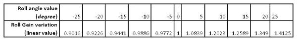
Table 2: Antenna relative gain as a function of the roll angle of the spacecraft.
The change of antenna gain in amplitude as a function of the spacecraft configuration can be found starting from values extracted from the auxiliary data of each data product for each data block. These values are those of the parameters describing the position of the solar panels and the HGA of the spacecraft, namely MRO_SAMX_INNER_GIMBAL_ANGLE, MRO_SAMX_OUTER_GIMBAL_ANGLE, MRO_SAPX_INNER_GIMBAL_ANGLE, MRO_SAPX_OUTER_GIMBAL_ANGLE, MRO_HGA_INNER_GIMBAL_ANGLE, and MRO_HGA_OUTER_GIMBAL_ANGLE (see Section 7.6). An average value of the outer gimbal angle for the solar panels needs to be computed to identify the type of configuration the spacecraft is in from Table 3
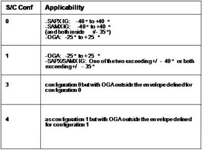
Table 3: Types of spacecraft configuration affecting SHARAD antenna gain. SAPXIG is the inner gimbal angle of the MRO solar array in the +X direction, SAMXIG is the inner gimbal angle of the MRO solar array in the -X direction, OGA is the outer gimbal angle of the MRO high gain antenna.
Once the spacecraft configuration type has been determined, Table 4 can be used to find the corresponding antenna gain variation relative to the base configuration (configuration 0, the so-called "spread eagle").

Table 4: Antenna relative gain as a function of the spacecraft configuration.
A deterministic correction of signal distortions due to the ionosphere would require a knowledge of its physical structure to a level of detail which is outside the capabilities of the suite of experiments on board MRO, and which cannot be extracted from detailed measurements done by other experiments in different times and places due to the high spatial and temporal variability of the ionosphere.
The correction implemented in the SHARAD ground processing software is thus an adaptive algorithm which does not require any prior knowledge of the ionosphere, called the Phase Gradient Autofocus (PGA) method, originally developed for Synthetic Aperture Radar (SAR) images [AD9]. The fundamental concept from which PGA was developed was to make a robust estimation of the derivative (gradient) of the phase error using only the defocused complex SAR image. The estimation process exploits the redundancy of the phase-error information contained in the degraded image, independent of the underlying scene content.
4.3.4 Data Flow
SHARAD science and engineering telemetry, as well as MRO spacecraft housekeeping telemetry, are retrieved from the MRO Project Distributed Object Management (DOM), through the SHARAD Science Operations Planning Computer (SOPC) located at JPL. SPICE kernels are obtained either through the MRO Project DOM or via the public NAIF server. Instrument and spacecraft telemetry, as well as SPICE kernels, are archived locally at the SHARAD operation center.
Once produced, SHARAD EDR Data Products, SHARAD Experiment Status Report Files and calibration files are archived locally at the SHARAD operation center. They are also made immediately available to SHARAD Team Members through a server located at the ASI Science Data Center (ASDC) in Frascati, Italy, and through a server provided by the PDS Geosciences Node and located at WashingtonUniversity, St. Louis, Missouri, USA, via a secure client-server protocol.
After a data validation period of 6 months or less, the SHARAD team will notify the Geosciences Node that certain products (SHARAD EDR Data Products, SHARAD Experiment Status Report Files, and calibration files) have been validated and are ready to be archived in PDS.
A single SHARAD EDR Data Product includes all data blocks belonging to a single data take, i.e. all data that have been acquired continuously in time using the same instrument mode and on-board processing settings, and thus acquired using parameters contained in a single entry of an OST. A data block is a single processed echo resulting from the on-board pre-summing of one or more echoes.
Data takes can be of virtually any duration, ranging from a few tens of seconds to twenty minutes or more, depending on a number of factors including the nature of the terrain being sounded and spacecraft operational constraints. Thus, the content of each SHARAD data product is highly variable in terms of number of data blocks, and depends on how operations for the instrument were planned for a given data collection period.
A better indication of the rate at which products are generated can be obtained by starting from the data volume allocated to SHARAD over the course of the mission [AD4]: for a 26 Tbits mission data volume over a 731 day mission duration, the resulting raw data volume generated by the instrument is, on average, 5.5 Gbits per day. Note that actual mission data volume may be higher than the planned 26 Tbits: it is currently deemed possible that the total data volume downlinked from the spacecraft can reach 50 Tbits, resulting in an average raw data production rate of 10.5 Gbits per day.
Level 1A processing to generate EDR Data Products results in an increase of data volume, because scientific telemetry is basically left untouched, while PDS headers and auxiliary data needed to locate each observation in space and time are added. In the high data volume case, it is estimated that 10.6 Gbits of EDR Data Products are generated on average each day, for a total of 7.6 Tbits of EDR data over the course of the nominal mission.
Examination of different operation scenarios of the instrument provides an indication of the number of daily data takes, and thus of the number of EDR Data Products, ranging from a few to several tens, for an average number that is currently estimated at around 10. This results in an average EDR Data Product size of approximately 135 MBytes, and in a total of about 8000 EDR Data Products over the course of the mission, with a wide margin of variation for both estimates.
Data products will be delivered to the PDS Geosciences Node according to the schedule originally specified in the MRO Archive Plan [AD4], as maintained and updated by the MRO Data and Archives Working Group.
EDR Data Products may be re-processed if either the processing software or input data such as spacecraft reconstructed trajectory are updated or corrected. In such an instance, it is expected that the data will be reprocessed and re-delivered to the PDS Geosciences Node at the first opportunity, i.e. at the following delivery of new data to PDS.
4.3.5 Labeling and Identification
SHARAD data products consist of three files each, the first of which contains instrument data, and is called a Science Telemetry file, while the second, called an Auxiliary Data file contains geometric information used to locate observations in space and time. The third file is the detached PDS label describing the content of the two previous files.
The file naming scheme adheres to the ISO Level II 27.3 file name convention to be compliant with PDS standard. File names are built by a concatenation of up to seven identifiers separated by underscore characters ("_"), followed by a dot and a three-letter extension. Each identifier provides one type of information on the content of the file. Identifiers are concatenated in the following order, although not all of them are necessarily present in any given file name:
<Data product>_<Transaction ID>_<OST line #>_<Operative mode>_<PRF>_<Version>_<File type>.<Extension>
The data product identifier is the character "E", denoting an Experimental Data Record product.
The transaction ID is a 7-digit number associated with the transaction ID (sometimes called product ID or observation ID) contained in the Instrument Raw Science Product filename [AD12] from which the EDR is produced, and uniquely identifying the Operation Sequence Table used during data acquisition. The first five digits of the transaction ID correspond to the number of the orbit in which data were acquired, while the last two digits denote the number of the OST that was used during data acquisition.
The Operation Sequence Table line number is the three-digit number of the OST line being used during data acquisition.
Operative modes have been defined in Section 4.1.1. Operative mode identifiers consist of two letters followed by a two-digit number, the two letters being either SS (for sub-surface sounding) or RO (for receive only), while the number ranges from 01 to 21 and is associated to the number of pre-summed echoes in a data block and to the bit resolution of each sample, as illustrated in Table 1.
The Pulse Repetition Frequency (PRF) identifier is a three-digit number corresponding to the integer part of the PRF value used in acquiring data. Thus, valid values for this identifier are 335, 350, 387, 670, 700 and 775, as listed in [AD8, Section 3.5.5.5].
The version identifier is a single character denoting the current version of the data product, and ranges from A to Z.
The file type identifier denotes the type of binary file: a Science Telemetry file is denoted by the identifier S, while an Auxiliary Data file is marked by the identifier A. The associated detached PDS label has no file type identifier in its file name.
File extension defines the format of data contained in the file: the extension is ".DAT" for Science Telemetry and Auxiliary Data files, denoting that the file contains a binary table object, and ".LBL" for the associated detached PDS label.
Files belonging to the same data product have identical names except for file type identifier and extension.
Permitted values for different file name identifiers are listed in Table 5 below.
|
Data product |
Transaction ID |
OST line # |
Operative mode |
PRF |
Version |
File type |
Extension |
|
E |
0000000 ¼ 9999999 |
000 … 999 |
RO01 ¼ RO21 SS01 ¼ SS21 |
335 350 387 670 700 775 |
A ¼ Z |
S A |
.DAT .LBL |
Table 5: Permitted values for identifiers used in building EDR data product file names.
For example, the first version of a data product containing all data acquired during the measurements relative to the fifth Operation Sequence Table in orbit 1234, using the first OST line, in Subsurface Sounding mode at 700.28 Hz pulse repetition frequency with no pre-summed echoes per data block and 8-bit resolution per sample, would consist of the following three files:
· Instrument data binary file: E_0123405_001_SS07_700_A_S.DAT
· Geometric information binary file: E_0123405_001_SS07_700_A_A.DAT
· Associated detached PDS label: E_0123405_001_SS07_700_A.LBL
A data product is identified by the part of the file name common to all three files of which it consists, that is
<Data product>_<Transaction ID>_<OST line #>_<Operative mode>_<PRF>_<Version>
Thus, in the previous example, the data product would be identified as
E_0123405_001_SS07_700_A
This value would be reported as the PRODUCT_ID value in the detached PDS label.
Individual EDR products may be revised during the course of the mission. A product's revision status is recorded both in the name of files constituting the data product and in its PDS label using the keyword PRODUCT_VERSION_ID. The value of this keyword is "A" for the first version of a product. The value is incremented with each product revision. Also, the label keyword PRODUCT_CREATION_TIME is updated with each product revision.
The PDS label also includes a RELEASE_IDkeyword to indicate the number of the data release in which the product was included. The first release of the mission has a RELEASE_ID value of "0001"; the second release three months later has a value of "0002", and so on. This keyword is not updated for a revised product; it always shows the ID of the release in which the product first appeared.
PRODUCT_VERSION_ID, PRODUCT_CREATION_TIME, and RELEASE_ID appear in the index table for the EDR archive so that the set of revised products can be easily identified.
The minimum unit for reprocessing of data products is the release: thus, if any data products belonging to a given release need to be reprocessed, all data products belonging to that release will be reprocessed as well. Older versions of data products will be erased upon the availability of a new version, so that the EDR archive contains only one version of a given data product. Because reprocessing is handled at the release level, data products in different releases may have a different value for PRODUCT_VERSION_ID.
4.4 Standards Used in Generating Data Products
4.4.1 PDS Standards
All data released by the SHARAD Team for archiving are required to be compliant with the Planetary Data System standard [AD1, AD2, AD3]. This standard imposes requirements on several aspects of the data product generation process, among which there is need for detailed documentation describing the origin, structure and processing undergone by data, for their accurate location in space and time, and in general for all auxiliary and ancillary data which are needed for the scientific use of the data product. Also, such information has to be provided in an Object Description Language (ODL), in the format keyword = value, where keyword is a standard term used to label a parameter (e.g. latitude), and value is any allowed information quantifying that parameter.
4.4.2 Time Standards
4.4.2.1 START_TIME and STOP_TIME Formation
The PDS formation rule for dates and time in UTC is: YYYY-DDDThh:mm:ss.fff, with
· YYYY year (0000-9999)
· DDD day of year (001-366)
· T date/time separator
· hh hour (00-23)
· mm minute (00-59)
· ss second (00-59)
· fff fractions of second (000-999) (restricted to 3 digits)
4.4.2.2 SC_CLOCK_START_COUNT and SC_CLOCK_STOP_COUNT
The SC_CLOCK*COUNTS represents the on-board time counters (OBT) of the spacecraft and instrument computers. This OBT counter is given in the headers of the experiment telemetry source packets. It contains the data acquisition start time as 32 bit of unit seconds followed by 16 bit of fractional seconds. The time resolution of the fractional part is 2-16 = 1.53 10-5 seconds. Thus the OBT is represented as a decimal real number in floating-point notation with 5 digits after the decimal point. A reset of the spacecraft clock is represented by an integer number followed by a slash, e.g. "1/" or "2/".
Example 1: spacecraft_CLOCK_START_COUNT = "1/21983325.39258"
Example 2: spacecraft_CLOCK_START_COUNT = "21983325.39258"
Example 3: spacecraft_CLOCK_START_COUNT = "2/0000325.39008"
Example 1 and Example 2 represents the same time instance.
4.4.3 Coordinate Systems
SHARAD EDR data products will conform to a Project-determined set of cartographic standards. All map-projected data will use planetocentric coordinates and east-positive longitudes in the range 0° - 360°, computed w.r.t. the IAU 2000 reference ellipsoid [AD16]. Vector quantities such as spacecraft positions will be expressed in a Cartesian planetocentric reference frame.
4.4.4 Data Storage Conventions
Binary files are all fixed-length records, stored in most-significant-byte-first (big-endian) format. The EDR files will be produced on a PC running the Linux operating system. The PDS labels are stored as ASCII character strings conforming to the conventions outlined in the PDS Standards Reference [AD1]. In text files, each record is terminated with a carriage return followed by a line feed.
4.5 Data Validation
SHARAD Experiment Data Records will be validated before being released to the PDS. Validation is accomplished in two parts: validation for scientific integrity and validation for compliance with PDS standards.
SHARAD Team members are expected to conduct validation for scientific integrity in the course of their analysis of the products. Science validation is meant to ensure that data products contain the expected measurements and that they are otherwise suitable for analysis. The details of the science validation process are the responsibility of the SHARAD Team.
Validation for PDS compliance will be performed by the Geosciences Node and is meant to ensure that data products conform to PDS standards and to the specifications in this SIS.
A data set will pass a peer review before it is accepted by PDS. The SHARAD Team and the associated PDS Node will convene a peer review committee made up of scientists and data engineers. The committee will examine the data set to make sure it is complete and meets the product specifications as defined in the SIS. The committee will include a PDS representative to ensure that the data set is in compliance with PDS standards.
5 Detailed Data Product Specifications
5.1 Data Product Structure and Organization
Each SHARAD-EDR product is a collection of radar echoes at full (as downloaded) resolution, time ordered, with duplicates and transmission errors removed, and located in space and time.
Each EDR is composed of three files: one contains the down-linked data after zero-padding of corrupted packets, and the other contains parameters describing the observation geometry, which have been computed on ground using auxiliary data from the spacecraft . The third file is a detached PDS label describing the content of the two binary tables. A label file is stored in the same directory as the data files it describes. Note that, because of zero padding, the number of records in a partly corrupted data product is the same as if no packets were lost.
Data in both files are organized as tables: a line of the table corresponds to a single data block, and lines are ordered in the same way within both files; each column in the table correspond to an echo sample or to a parameter.
Detached PDS labels contain a description of the table object in the files, and pointers to structure files in the LABEL directory describing each column of the tables.
Because it is estimated that a large number of data files will be produced, the directory containing them will be further divided into a number of subdirectories, each containing data collected through the use of a single Operation Sequence Table. These subdirectory will be named so as to make clear which data products they contain and when such data were collected. Their name will be in the form pppnnnnnoo, where ppp is a group of letters denoting the kind of data product contained in the subdirectory (EDR for Experiment Data Records), nnnnn is the number of the orbit in which data were acquired, and oo is the number of the Operation Sequence Table in that orbit through which data were acquired: for example, the subdirectory named EDR0123405 will contain all files of Level 1A data collected in orbit 1234 with the instrument settings contained in the fifth Operation Sequence Table of that orbit.
5.2 Data Format Descriptions
Each SHARAD EDR data product consists of two binary files in fixed record-length format, called respectively the Science Telemetry and the Auxiliary Data files. The structure of such files is described by a separate PDS label containing also information on source data, production process, relation between stored bytes and physical quantities, product identification, storing and organizing of ancillary data and descriptive information needed to interpret and process the data. An example label is given in Appendix 7.3, and definitions of the label keywords in Appendix 7.4.
The structure of data contained in the Science Telemetry file and in the Auxiliary Data file is that of a PDS Table object [AD1]. The PDS label contains pointers to files containing definitions of the columns of such Table objects: Appendix 7.5 lists such definitions for Science telemetry files, while Appendix 7.6 provides definitions for Auxiliary Data files.
Each record in a binary Science Telemetry file is a Science Data Format as described in [AD11, Section 5.2], without the MROSP header, some internal telemetry counters, the Start of Telemetry and End of Telemetry markers and the checksum. It thus consists of an ancillary data header reporting the OST line used in collecting the data block, ancillary data reporting the time of acquisition of the data and listing parameter values used in on-board processing the data block, and the data block itself, consisting of 3600 echo samples, each either 4-, 6- or 8-bits long. The resulting record length in bytes is thus dependent of the Operative Mode through which data were acquired, and is reported in Table 6.
|
Instrument Operative Mode |
Bits per Sample |
Samples per Data Block |
Ancillary Data Header Bytes |
Ancillary Data Bytes |
Record length in Bytes for the corresponding Science Telemetry file |
|
RO01, RO04, RO07, RO10, RO13, RO16, RO19 SS01, SS04, SS07, SS10, SS13, SS16, SS19 |
8 |
3600 |
46 |
140 |
3786 |
|
RO02, RO05, RO08, RO11, RO14, RO17, RO20 SS02, SS05, SS08, SS11, SS14, SS17, SS20 |
6 |
3600 |
46 |
140 |
2886 |
|
RO03, RO06, RO09, RO12, RO15, RO18, RO21 SS03, SS06, SS09, SS12, SS15, SS18, SS21 |
4 |
3600 |
46 |
140 |
1986 |
Table 6: record length in binary Science Telemetry files of an EDR data product as a function of the Operative Mode.
Each record in a binary Auxiliary Data file is the line of a table listing values of geometric and engineering parameters relevant for the location and processing of the corresponding data block in the Science Telemetry file. Most parameter values are expressed as an 8-byte or 4-byte IEEE real number. Values contained in this file are partly computed from SPICE kernels containing information on spacecraft trajectory and attitude, and partly extracted from SHARAD housekeeping telemetry.
5.3 Label and Header Descriptions
PDS labels are written in Object Description Language (ODL) [AD1]. PDS label statements have the form of "keyword = value". Each label statement is terminated with a carriage return character (ASCII 13) and a line feed character (ASCII 10) sequence to allow the label to be read by many operating systems.
The labels contained in SHARAD EDR files conform to the general structure used for all PDS detached labels [AD1]. The metadata in the label can be divided into seven categories as follows:
The first and shortest is the label standards specifier, which indicates the PDS standards version that applies to the label. The second group of keywords consists of identification data elements that give information about the dataset. These include identifiers for the specific data product and the PDS dataset to which it belongs; information about the input data such as spacecraft, instrument, and time range of data; and information about the product creation process.
This is followed by file characteristics for the binary files of the data product (Science Telemetry and Auxiliary Data), such as the record format, record length, and number of records. Next, pointers to the data product binary files containing the data objects are given; for the SHARAD EDRs, such objects are PDS Table objects. Pointer statements have the following format:
^object = file name
where the caret character (^, also called a pointer) is followed by the name of the specific data object. The string after the "=" sign is the name of the file containing the data object.
Following the object pointer is a set of identification data elements that give information about the input data used to produce the data object. Then follow descriptive data elements providing information about the content of the data object. These include instrument setup during data collection and an assessment of data quality in terms of the percentage of missing packets within the data product.
Finally, definitions of the data objects in the files are given. The Table object definition contains information about the size, data type, scaling, and special values of the data. This object also contains a pointer to another file that contains the table column definitions, in order to avoid repeating the lengthy definitions in every label. These column definition files have the extension ".FMT" and are stored in the LABEL directory of the EDR archive. The data files themselves do not contain any embedded headers. Examples of SHARAD EDR labels and Table object column definitions are found in Appendix 7.3, 7.4, 7.5 and 7.6 to this document.
6 Applicable Software
6.1 Applicable PDS Software Tools
SHARAD EDR data products can be read by the PDS software NASAView, which reads a PDS label and displays the associated image or table. NASAView is free software and is available for several computer platforms.
NASAView is a PDS archive product display program that runs on multiple platforms in a GUI environment. This application was built using the Label Library Light (L3), Object Access Library (OAL) and the XVT Development Solution for C package. Label Library Light parses PDS ODL labels and creates an in-memory representation of the label information. The object access library uses the parse tree and accesses the actual PDS object. The XVT Development solution supplies the cross platform GUI and an object-oriented environment. XVT allows the definition and code with them.
NASAView has been tested on both EDR and RDR data products, and a few minor problems have been found.
While there are some unusual numeric formats representing parameter values throughout EDR data products, NASAView is usually capable of reading them. The only exception are three-byte unsigned integers, which are displayed as asterisks. There are only two instances of such format, namely the parameters DATA_BLOCK_ID and DATA_BLOCK_FIRST_PRI in EDR data products, which are tags for records within a data product.
In reading a binary table, NASAView displays the name of the column as well as its content. It has been found, however, that such name must be less than 30 character long, otherwise the displayed column name is blank.
Finally, while NASAView is able to display individual ITEMs in a COLUMN object, it seems incapable of doing so for ITEMs in BIT_COLUMN objects.
6.2 Software Distribution and Update Procedures
NASAView is available for free from the Planetary Data System, but the source code is not available. Platforms supported are LINUX, SOLARIS, Windows and Power MAC. The executable of the program can be downloaded following links found at http://pds.jpl.nasa.gov/tools/software_download.cfm
For updates to the software, users may visit the web site or register with the PDS Subscription Service at http://pds.jpl.nasa.gov/.
7 Appendices
7.1 Acronyms
|
ADC |
Analog to Digital Converter |
|
ASDC |
ASI Science data Center |
|
ASI |
Agenzia Spaziale Italiana (Italian Space Agency) |
|
CODMAC |
Committee On Data Management And Computation |
|
DCG |
Digital Chirp Generator |
|
DES |
Digital Electronics Subsystem |
|
DOM |
Distributed Object Management |
|
EDR |
Experiment Data Record |
|
HGA |
High Gain Antenna |
|
INFOCOM |
[Dipartimento di] Scienza e Tecnica dell'Informazione e della Comunicazione ([Department of] Science and Technology of Information and Communications) |
|
JPL |
Jet Propulsion Laboratory |
|
MRO |
Mars Reconnaissance Orbiter |
|
NAIF |
Navigation and Ancillary Information Facility at JPL |
|
NASA |
National Aeronautics and Space Administration |
|
OBT |
On Board Time |
|
ODL |
Object Description Language |
|
ODT |
Orbital Data Table |
|
OST |
Operation Sequence Table |
|
PDS |
Planetary Data System |
|
PGA |
Phase Gradient Autofocus |
|
PRF |
Pulse Repetition Frequency |
|
PRI |
Pulse Repetition Interval |
|
PT |
Parameters Table |
|
Rx |
Receiver |
|
SAR |
Synthetic Aperture Radar |
|
SHARAD |
SHAllow RADar |
|
SIS |
Software Interface Specification |
|
SPICE |
Geometric and ancillary data (Spacecraft, Planet, Instrument, C-kernel, and Event) |
|
SSR |
Solid State Recorder |
|
Tx |
Transmitter |
|
UTC |
Coordinated Universal Time |
Table 7: List of acronyms used throughout this document.
7.2 Definitions of Data Processing Levels
|
NASA |
CODMAC |
Description |
|
Packet data |
Raw - Level 1 |
Telemetry data stream as received at the ground station, with science and engineering data embedded. |
|
Level-0 |
Edited - Level 2 |
Instrument science data (e.g., raw voltages, counts) at full resolution, time ordered, with duplicates and transmission errors removed. |
|
Level 1A |
Calibrated - Level 3 |
Level 0 data that have been located in space and may have been transformed (e.g., calibrated, rearranged) in a reversible manner and packaged with needed ancillary and auxiliary data (e.g., radiances with the calibration equations applied). |
|
Level 1B |
Resampled - Level 4 |
Irreversibly transformed (e.g., resampled, remapped, calibrated) values of the instrument measurements (e.g., radiances, magnetic field strength). |
|
Level 1C |
Derived - Level 5 |
Level 1A or 1B data that have been resampled and mapped onto uniform space-time grids. The data are calibrated (i.e., radiometrically corrected) and may have additional corrections applied (e.g., terrain correction). |
|
Level 2 |
Derived - Level 5 |
Geophysical parameters, generally derived from Level 1 data, and located in space and time commensurate with instrument location, pointing, and sampling. |
|
Level 3 |
Derived - Level 5 |
Geophysical parameters mapped onto uniform space-time grids. |
Table 8: Equivalence between NASA and CODMAC data processing level.
7.3 Example PDS Label
Below is listed the content of the label file E_0168901_002_SS19_700_A.LBL.
/* Label standard identifier */
PDS_VERSION_ID = PDS3
/* Identification data elements that apply to all referenced data files */
DATA_SET_ID = "MRO-M-SHARAD-3-EDR-V1.0"
PRODUCT_ID = "E_0168901_002_SS19_700_A"
RELEASE_ID = "0001"
PRODUCT_TYPE = EDR
INSTRUMENT_HOST_ID = MRO
INSTRUMENT_HOST_NAME = "MARS RECONNAISSANCE ORBITER"
INSTRUMENT_ID = SHARAD
INSTRUMENT_NAME = "SHALLOW RADAR"
INSTRUMENT_TYPE = RADAR
TARGET_NAME = MARS
MISSION_PHASE_NAME = "MAPPING"
ORBIT_NUMBER = 1689
MRO:START_SUB_SPACECRAFT_LATITUDE = 61.070977 <DEGREES>
MRO:STOP_SUB_SPACECRAFT_LATITUDE = 59.706975 <DEGREES>
MRO:START_SUB_SPACECRAFT_LONGITUDE= 229.725482 <DEGREES>
MRO:STOP_SUB_SPACECRAFT_LONGITUDE = 229.355538 <DEGREES>
START_TIME = 2006-340T02:09:41.792
STOP_TIME = 2006-340T02:10:07.782
SPACECRAFT_CLOCK_START_COUNT = "2/849838181.51915"
SPACECRAFT_CLOCK_STOP_COUNT = "2/849838207.51298"
PRODUCT_CREATION_TIME = 2007-129T17:41:32.000
PRODUCT_VERSION_ID = "A"
PRODUCT_VERSION_TYPE = RECONSTRUCTED
OBJECT = FILE
/* File characteristic data elements */
RECORD_TYPE = FIXED_LENGTH
RECORD_BYTES = 3786
FILE_RECORDS = 4551
/* Data object pointers */
^SCIENCE_TELEMETRY_TABLE = "E_0168901_002_SS19_700_A_S.DAT"
/* Identification data elements */
SOURCE_PRODUCT_ID = {"4A_07_0A11398800_01.DAT"}
/* Descriptive data elements */
INSTRUMENT_MODE_ID = SS19
INSTRUMENT_MODE_DESC = "In this mode the instrument performs
scientific measurements by transmitting
radar pulses and collecting, processing
and formatting received echoes. Data
processing performed on-board consists
in summing 04 sequential echoes, and
converting the result from 32-bit
precision to 08-bit precision."
MRO:PULSE_REPETITION_INTERVAL = 1428 <MICROSECONDS>
MRO:PHASE_COMPENSATION_TYPE = "NO COMPENSATION"
MRO:MANUAL_GAIN_CONTROL = 10
MRO:COMPRESSION_SELECTION_FLAG= "STATIC"
MRO:CLOSED_LOOP_TRACKING_FLAG = "DISABLED"
DATA_QUALITY_ID = "0"
DATA_QUALITY_DESC = "0:no corrupted data
1:less than 2% corrupted data
2:less than 5% corrupted data
3:less than 10% corrupted data
4:more than 10% corrupted data"
/* Data object definitions */
OBJECT = SCIENCE_TELEMETRY_TABLE
INTERCHANGE_FORMAT = BINARY
COLUMNS = 39
ROW_BYTES = 3786
ROWS = 4551
DESCRIPTION = "Binary table containing raw science
telemetry packets generated by SHARAD,
called blocks, collected continuously
using the same operation mode, instrument
status and on-board processing scheme.
Each data block is a sequence of time
samples of a received signal, preceded by
a header containing information on the
collection and on-board processing of the
data. In the table, each line contains
data from a single data block, and each
column contains the value of a single
parameter or time sample across different
data blocks."
^STRUCTURE = "SCIENCE8BIT.FMT"
PRIMARY_KEY = ("SCET_BLOCK_WHOLE","SCET_BLOCK_FRAC")
START_PRIMARY_KEY = (849838181,51915)
STOP_PRIMARY_KEY = (849838207,51298)
END_OBJECT = SCIENCE_TELEMETRY_TABLE
END_OBJECT = FILE
OBJECT = FILE
/* File characteristic data elements */
RECORD_TYPE = FIXED_LENGTH
RECORD_BYTES = 267
FILE_RECORDS = 4551
/* Data object pointers */
^AUXILIARY_DATA_TABLE = "E_0168901_002_SS19_700_A_A.DAT"
/* Identification data elements */
SPICE_FILE_NAME= {"CK_RPred_06337_06344_hga_20061213214649.bc",
"mro_hga_psp_061205_061211.bc",
"mro_hga_2006-12-11.bc",
"CK_Pred_06346_06358_hga_20061212190113.bc",
"mro_hga_2006-12-10.bc",
"CK_Pred_06347_OA34_hga_20061212020103.bc",
"mro_hga_2006-12-09.bc",
"mro_hga_2006-12-08.bc",
"mro_hga_2006-12-07.bc",
"DESAT_ATT_PREDICT_06351_06358_RM004_fixed_desat_hga_20061208202007.bc",
"mro_hga_2006-12-06.bc",
"mro_hga_psp_061128_061204.bc",
"mro_hga_2006-12-05.bc",
"CK_RPred_06330_06338_hga_20061206214511.bc",
"DESAT_ATT_PREDICT_06351_07007_RM004_hga_20061206135417.bc",
"mro_hga_2006-12-04.bc",
"CK_Pred_06338_06351_hga_20061205171215.bc",
"mro_hga_2006-12-03.bc",
"mro_hga_2006-12-02.bc",
"mro_hga_2006-12-01.bc",
"mro_hga_2006-11-30.bc",
"mro_hga_2006-11-29.bc",
"ATT_PREDICT_SLCAL_06345_rev_hga_20061201021903.bc",
"ATT_PREDICT_SLCAL_06345_hga_20061130175304.bc",
"mro_hga_2006-11-28.bc",
"CK_RPred_06323_06330_hga_20061129225109.bc",
"CK_Pred_06331_06344_hga_20061129203816.bc",
"CK_RPred_06315_06323_hga_20061129201112.bc",
"mro_hga_psp_061121_061127.bc",
"mro_hga_2006-11-27.bc",
"CK_RPred_06337_06344_sa_20061213214649.bc",
"mro_sa_psp_061205_061211.bc",
"mro_sa_2006-12-11.bc",
"CK_Pred_06346_06358_sa_20061212190113.bc",
"mro_sa_2006-12-10.bc",
"CK_Pred_06347_OA34_sa_20061212020103.bc",
"mro_sa_2006-12-09.bc",
"mro_sa_2006-12-08.bc",
"mro_sa_2006-12-07.bc",
"DESAT_ATT_PREDICT_06351_06358_RM004_fixed_desat_sa_20061208202007.bc",
"mro_sa_2006-12-06.bc",
"mro_sa_psp_061128_061204.bc",
"mro_sa_2006-12-05.bc",
"CK_RPred_06330_06338_sa_20061206214511.bc",
"DESAT_ATT_PREDICT_06351_07007_RM004_sa_20061206135417.bc",
"mro_sa_2006-12-04.bc",
"CK_Pred_06338_06351_sa_20061205171215.bc",
"mro_sa_2006-12-03.bc",
"mro_sa_2006-12-02.bc",
"mro_sa_2006-12-01.bc",
"mro_sa_2006-11-30.bc",
"mro_sa_2006-11-29.bc",
"ATT_PREDICT_SLCAL_06345_rev_sa_20061201021903.bc",
"ATT_PREDICT_SLCAL_06345_sa_20061130175304.bc",
"mro_sa_2006-11-28.bc",
"CK_RPred_06323_06330_sa_20061129225109.bc",
"CK_Pred_06331_06344_sa_20061129203816.bc",
"CK_RPred_06315_06323_sa_20061129201112.bc",
"mro_sa_psp_061121_061127.bc",
"mro_sa_2006-11-27.bc",
"mro_sc_psp_061205_061211.bc",
"CK_RPred_06337_06344_sc_20061213214649.bc",
"mro_sc_2006-12-11.bc",
"CK_Pred_06346_06358_sc_20061212190113.bc",
"mro_sc_2006-12-10.bc",
"CK_Pred_06347_OA34_sc_20061212020103.bc",
"mro_sc_2006-12-09.bc",
"mro_sc_2006-12-08.bc",
"mro_sc_2006-12-07.bc",
"DESAT_ATT_PREDICT_06351_06358_RM004_fixed_desat_sc_20061208202007.bc",
"mro_sc_2006-12-06.bc",
"mro_sc_psp_061128_061204.bc",
"mro_sc_2006-12-05.bc",
"CK_RPred_06330_06338_sc_20061206214511.bc",
"DESAT_ATT_PREDICT_06351_07007_RM004_sc_20061206135417.bc",
"mro_sc_2006-12-04.bc",
"DESAT_ATT_PREDICT_06351_07007_RM004_sc_20061206135417.bc",
"mro_sc_2006-12-05_stracker_ql1.bc",
"CK_Pred_06338_06351_sc_20061205171215.bc",
"mro_sc_2006-12-03.bc",
"mro_sc_2006-12-02.bc",
"mro_sc_2006-12-01.bc",
"mro_sc_2006-11-30.bc",
"mro_sc_2006-11-29.bc",
"ATT_PREDICT_SLCAL_06345_rev_sc_20061201021903.bc",
"ATT_PREDICT_SLCAL_06345_sc_20061130175304.bc",
"mro_sc_2006-11-28.bc",
"mro_sc_psp_061121_061127.bc",
"CK_RPred_06323_06330_sc_20061129225109.bc",
"CK_Pred_06331_06344_sc_20061129203816.bc",
"naif0008.tls",
"pck00008.tpc",
"MRO_SCLKSCET.00019.65536.tsc",
"de410.bsp",
"spk_psp_rec01754_01673_01754_r-v1.bsp",
"mro_v08.tf",
"MRO_SCLKSCET.00019.tsc"}
/* Data object definitions */
OBJECT = AUXILIARY_DATA_TABLE
INTERCHANGE_FORMAT = BINARY
COLUMNS = 38
ROW_BYTES = 267
ROWS = 4551
DESCRIPTION = "Binary table listing geometric quantities
generated on-ground from spacecraft
navigation data, parameters extracted from
instrument and spacecraft housekeeping
telemetry, and flags describing the
completeness and usability of scientific
data. This table is associated to a binary
file containing instrument science
telemetry, and contains one line for each
line in the science telemetry binary
table."
^STRUCTURE = "AUXILIARY.FMT"
PRIMARY_KEY = ("SCET_BLOCK_WHOLE","SCET_BLOCK_FRAC")
START_PRIMARY_KEY = (849838181,51915)
STOP_PRIMARY_KEY = (849838207,51298)
END_OBJECT = AUXILIARY_DATA_TABLE
END_OBJECT = FILE
END
7.4 PDS Label Keywords
The following table lists in alphabetical order the keywords appearing in an EDR data product PDS label, together with an explanation of its meaning and a set of valid values.
|
Keyword name |
Definition |
Type |
Valid values |
|
COLUMNS |
Number of columns in each row of a data object. |
INTEGER |
39 (Science Telemetry) 38 (Auxiliary Data) |
|
DATA_QUALITY_DESC |
Description of the data quality which is associated with a particular DATA_QUALITY_ID value. |
CHARACTER |
" 0: no corrupted data 1: less than 2% corrupted data 2: less than 5% corrupted data 3: less than 10% corrupted data 4: more than 10% corrupted data" |
|
DATA_QUALITY_ID |
Numeric key which identifies the quality of data in the data product. |
CHARACTER |
"0", "1", "2", "3", "4", "N/A" |
|
DATA_SET_ID |
Unique alphanumeric identifier for a data set or a data product. The DATA_SET_ID value for a given data set or product is constructed according to flight project naming conventions. |
CHARACTER |
"MRO-M-SHARAD-3-EDR-V1.0" |
|
DESCRIPTION |
Free-form, unlimited-length character string that represents or gives an account of something. |
CHARACTER |
Text describing the content of a data object. |
|
FILE_RECORDS |
Number of physical file records. |
INTEGER |
Number of Data Blocks in the Data Product. |
|
INSTRUMENT_HOST_ID |
Unique identifier for the host where an instrument is located. |
CHARACTER |
MRO |
|
INSTRUMENT_HOST_NAME |
Full name of the host on which an instrument is based. |
CHARACTER |
"MARS RECONNAISSANCE ORBITER" |
|
INSTRUMENT_ID |
Abbreviated name or acronym which identifies an instrument. |
CHARACTER |
SHARAD |
|
INSTRUMENT_MODE_DESC |
Description of the instrument mode which is identified by the INSTRUMENT_MODE_ID element. |
CHARACTER |
Text providing a brief account of the characteristics of the instrument Operative Mode. |
|
INSTRUMENT_MODE_ID |
Instrument-dependent designation of operating mode. |
CHARACTER |
RO01 ¼ RO21 SS01 ¼ SS21 |
|
INSTRUMENT_NAME |
Full name of an instrument. |
CHARACTER |
"SHALLOW RADAR" |
|
INSTRUMENT_TYPE |
Type of an instrument. |
CHARACTER |
RADAR |
|
INTERCHANGE_FORMAT |
Manner in which data items are stored. |
CHARACTER |
BINARY |
|
MISSION_PHASE_NAME |
Commonly-used identifier of a mission phase. See [AD4, Table 9] for timing of mission phases. |
CHARACTER |
"CRUISE", "AEROBRAKING", "MAPPING", "EXTENDED MISSION" |
|
MRO:CLOSED_LOOP_TRACKING_FLAG |
Flag used by the SHARAD on-board processing software to enable or disable the closed-loop tracking algorithm. See Section 4.1.3.3 for explanations |
CHARACTER |
"ENABLED", "DISABLED" |
|
MRO:COMPRESSION_SELECTION_FLAG |
Flag used by the SHARAD on-board processing software to enable or disable the dynamic scaling algorithm. See Section 4.1.3.4 for explanations |
CHARACTER |
"STATIC", "DYNAMIC" |
|
MRO:MANUAL_GAIN_CONTROL |
Parameter used by the SHARAD on-board processing software to set the receiver gain to a fixed value during data acquisition. |
INTEGER |
0 … 255 |
|
MRO:PHASE_COMPENSATION_TYPE |
Parameter used by the SHARAD on-board processing software to select the type of time shifting applied to received echoes before coherent summing. |
CHARACTER |
"NO COMPENSATION", "RADIAL VELOCITY", "SURFACE SLOPE", "RADIAL VELOCITY AND SURFACE SLOPE" |
|
MRO:PULSE_REPETITION_INTERVAL |
Time between the transmission of two consecutive pulses, expressed in microseconds. |
INTEGER |
1428, 1492, 1290, 2856, 2984, 2580 |
|
MRO:START_SUB_SPACECRAFT_LATITUDE |
Planetocentric latitude of the sub-spacecraft point at the beginning of data collection. |
REAL |
-90 … 90 |
|
MRO:START_SUB_SPACECRAFT_LONGITUDE |
Planetocentric east longitude of the sub-spacecraft point at the beginning of data collection. |
REAL |
0 … 360 |
|
MRO:STOP_SUB_SPACECRAFT_LATITUDE |
Planetocentric latitude of the sub-spacecraft point at the end of data collection. |
REAL |
-90 … 90 |
|
MRO:STOP_SUB_SPACECRAFT_LONGITUDE |
Planetocentric east longitude of the sub-spacecraft point at the end of data collection. |
REAL |
0 … 360 |
|
ORBIT_NUMBER |
The ORBIT_NUMBER element identifies the number of the orbital revolution of the spacecraft around a target body. |
INTEGER |
0 … 99999 |
|
PDS_VERSION_ID |
Version number of the PDS standards documents that is valid when a data product label is created |
CHARACTER |
"PDS3" |
|
PRIMARY_KEY |
Names of columns in the table that may be used to uniquely identify each row in the table. |
CHARACTER |
( "SCET_BLOCK_WHOLE", "SCET_BLOCK_FRAC" ) |
|
PRODUCT_CREATION_TIME |
UTC system format time when a product was created. See Section 4.4.2.1 for formation rules. |
CHARACTER |
Example: 2006-027T18:00:00.000 |
|
PRODUCT_ID |
Permanent, unique identifier assigned to a data product by its producer. See Section 4.3.5 for formation rules. |
CHARACTER |
Example: "E_0168901_002_SS19_700_A" |
|
PRODUCT_TYPE |
Type or category of a data product within a data set. |
CHARACTER |
EDR |
|
PRODUCT_VERSION_ID |
Version of an individual product within a data set. |
CHARACTER |
"A" … "Z" |
|
PRODUCT_VERSION_TYPE |
Version of an individual data product that might appear in several incarnations. |
CHARACTER |
"PREDICTED" (predicted spacecraft trajectory data), "RECONSTRUCTED" (reconstructed spacecraft trajectory data) |
|
RECORD_BYTES |
Number of bytes in a physical file record, including record terminators and separators. |
INTEGER |
1986, 2886, 3786 (Science Telemetry), 267 (Auxiliary Data) |
|
RECORD_TYPE |
Record format of a file. |
CHARACTER |
FIXED_LENGTH |
|
RELEASE_ID |
The RELEASE_ID element identifies the unique identifier associated with a specific release of a data set. See [AD4, Table 9] for timing of releases. |
CHARACTER |
"0001" … "9999" |
|
ROWS |
Number of rows in a data object. |
INTEGER |
Number of Data Blocks in the Data Product |
|
ROW_BYTES |
Number of bytes in each data object row. |
INTEGER |
1986, 2886, 3786 (Science Telemetry), 267 (Auxiliary Data) |
|
SOURCE_PRODUCT_ID |
Product used as input to create a new product. |
CHARACTER |
Name(s) of the Instrument Raw Science Product(s) [AD12] used in making the data product. |
|
SPACECRAFT_CLOCK_START_COUNT |
Value of the spacecraft clock at the time of acquisition of the first Data Block in the Data Product. See Section 4.4.2.2 for formation rules. |
CHARACTER |
Example: "2/0818975946.01161" |
|
SPACECRAFT_CLOCK_STOP_COUNT |
Value of the spacecraft clock at the time of acquisition of the last Data Block in the Data Product. See Section 4.4.2.2 for formation rules. |
CHARACTER |
Example: "2/0818975949.00906" |
|
SPICE_FILE_NAME |
Names of the SPICE files used in processing the data. |
CHARACTER |
Names of the SPICE kernels used in producing the geometry information in the data product. |
|
START_PRIMARY_KEY |
Beginning of the range of values for the PRIMARY_KEY column in the table. |
INTEGER |
SCET_BLOC_WHOLE and SCET_BLOCK_FRAC of the first Data Block in the Data Product. |
|
START_TIME |
Date and time of acquisition of the first Data Block in the Data Product in UTC system format. See Section 4.4.2.1 for formation rules. |
CHARACTER |
Example: 2005-123T21:18:48.409 |
|
STOP_PRIMARY_KEY |
End of the range of values for the PRIMARY_KEY column in the table. |
INTEGER |
SCET_BLOC_WHOLE and SCET_BLOCK_FRAC of the last Data Block in the Data Product. |
|
STOP_TIME |
Date and time of acquisition of the last Data Block in the Data Product in UTC system format. See Section 4.4.2.1 for formation rules. |
CHARACTER |
Example: 2005-123T21:18:51.405 |
|
TARGET_NAME |
Target of observation. |
CHARACTER |
MARS |
|
^AUXILIARY_DATA_TABLE |
Pointer to the file containing the auxiliary data Table object. |
CHARACTER |
Example: " E_0168901_002_SS19_700_A_A.DAT" |
|
^SCIENCE_TELEMETRY_TABLE |
Pointer to the file containing the science telemetry Table object. |
CHARACTER |
Example: " E_0168901_002_SS19_700_A_S.DAT" |
|
^STRUCTURE |
Pointer to the format descriptor of the Table object |
CHARACTER |
"AUXILIARY.FMT", "SCIENCE4BIT.FMT", "SCIENCE6BIT.FMT", "SCIENCE8BIT.FMT" |
Table 9: alphabetical list of keywords appearing in an EDR data product PDS label.
7.5 Science Telemetry Format Files
The Science Telemetry file of every EDR data product contains the instrument scientific telemetry as downlinked from the spacecraft. The Science Telemetry file is organized as a table, in which each record corresponds to a Data Block, organized as a Science Data Format whose structure is described in [AD11], but without the MROSP header, some internal telemetry counters, the Start of Telemetry and End of Telemetry markers and the checksum.
Columns of the table are described in separate files called format files. There is a different format file depending on the size of echo samples in bits (either 4, 6 or 8). Below is listed the content of the format file SCIENCE8BIT.FMT, describing the structure of science telemetry for 8-bit echo samples. Format files for 6-bit and 4-bit samples have a similar structure.
^ANCILLARY_STRUCTURE = "SCIENCE_ANCILLARY.FMT"
OBJECT = COLUMN
NAME = SCIENCE_DATA
DATA_TYPE = MSB_BIT_STRING
START_BYTE = 187
BYTES = 3600
OBJECT = BIT_COLUMN
NAME = ECHO_SAMPLES
BIT_DATA_TYPE = MSB_INTEGER
START_BIT = 1
BITS = 8
ITEMS = 3600
ITEM_BITS = 8
DESCRIPTION = "Array of 3600 samples of SHARAD echo return.
Each integer value is an antenna voltage
estimate at a particular instant in time.
These estimates are proportional to voltage
but are expressed in data numbers and need to
be converted to engineering units. The timing
of the samples and other relevant SHARAD
instrument parameters are included in the
ancillary data segment of each Data Block."
END_OBJECT = BIT_COLUMN
END_OBJECT = COLUMN
The content of the format file SCIENCE_ANCILLARY.FMT, describing the ancillary information accompanying echo samples, is listed below.
OBJECT = COLUMN
NAME = SCET_BLOCK_WHOLE
COLUMN_NUMBER = 1
DATA_TYPE = MSB_UNSIGNED_INTEGER
START_BYTE = 1
BYTES = 4
DESCRIPTION = "Spacecraft clock count at the time of data
block start of acquisition, integer seconds
part."
END_OBJECT = COLUMN
OBJECT = COLUMN
NAME = SCET_BLOCK_FRAC
COLUMN_NUMBER = 2
DATA_TYPE = MSB_UNSIGNED_INTEGER
START_BYTE = 5
BYTES = 2
DESCRIPTION = "Spacecraft clock count at the time of data
block start of acquisition, fractional seconds
part expressed in units of 2^-16 seconds."
END_OBJECT = COLUMN
OBJECT = COLUMN
NAME = TLM_COUNTER
COLUMN_NUMBER = 3
DATA_TYPE = MSB_UNSIGNED_INTEGER
START_BYTE = 7
BYTES = 4
DESCRIPTION = "Sequential counter uniquely identifying the
data block in the telemetry flux."
END_OBJECT = COLUMN
OBJECT = COLUMN
NAME = FMT_LENGTH
COLUMN_NUMBER = 4
DATA_TYPE = MSB_UNSIGNED_INTEGER
START_BYTE = 11
BYTES = 2
DESCRIPTION = "Length of the data block in bytes as formatted
by the instrument (excluding header and
trailer). Valid values are 1972 for 4-bit
modes, 2872 for 6-bit modes, 3772 for 8-bit
modes."
END_OBJECT = COLUMN
OBJECT = COLUMN
NAME = SPARE
COLUMN_NUMBER = 5
DATA_TYPE = MSB_UNSIGNED_INTEGER
START_BYTE = 13
BYTES = 2
DESCRIPTION = "All bits are set to 0."
END_OBJECT = COLUMN
OBJECT = COLUMN
NAME = SCET_OST_WHOLE
COLUMN_NUMBER = 6
DATA_TYPE = MSB_UNSIGNED_INTEGER
START_BYTE = 15
BYTES = 4
DESCRIPTION = "Spacecraft clock count at the start of
execution of the current Operation Sequence
Table, integer seconds part."
END_OBJECT = COLUMN
OBJECT = COLUMN
NAME = SCET_OST_FRAC
COLUMN_NUMBER = 7
DATA_TYPE = MSB_UNSIGNED_INTEGER
START_BYTE = 19
BYTES = 2
DESCRIPTION = "Spacecraft clock count at the start of
execution of the current Operation Sequence
Table, fractional seconds part expressed in
units of 2^-16 seconds."
END_OBJECT = COLUMN
OBJECT = COLUMN
NAME = SPARE
COLUMN_NUMBER = 8
DATA_TYPE = MSB_UNSIGNED_INTEGER
START_BYTE = 21
BYTES = 1
DESCRIPTION = "All bits are set to 0."
END_OBJECT = COLUMN
OBJECT = COLUMN
NAME = OST_LINE_NUMBER
COLUMN_NUMBER = 9
DATA_TYPE = MSB_UNSIGNED_INTEGER
START_BYTE = 22
BYTES = 1
DESCRIPTION = "Number of the Operation Sequence Table line in
execution."
END_OBJECT = COLUMN
OBJECT = COLUMN
NAME = OST_LINE
COLUMN_NUMBER = 10
DATA_TYPE = MSB_BIT_STRING
START_BYTE = 23
BYTES = 16
DESCRIPTION = "Operation Sequence Table line in execution; an
OST line defines the execution of a single
Operation Mode."
OBJECT = BIT_COLUMN
NAME = PULSE_REPETITION_INTERVAL
BIT_DATA_TYPE = MSB_UNSIGNED_INTEGER
START_BIT = 1
BITS = 4
DESCRIPTION = "This parameter is extracted from the Operation
Sequence Table. It is the time between the
transmission of two consecutive pulses, to be
used for the entire duration of the selected
Operation Mode:
- a value of 1 means 1428 microseconds;
- a value of 2 means 1492 microseconds;
- a value of 3 means 1290 microseconds;
- a value of 4 means 2856 microseconds;
- a value of 5 means 2984 microseconds;
- a value of 6 means 2580 microseconds."
END_OBJECT = BIT_COLUMN
OBJECT = BIT_COLUMN
NAME = PHASE_COMPENSATION_TYPE
BIT_DATA_TYPE = MSB_UNSIGNED_INTEGER
START_BIT = 5
BITS = 4
DESCRIPTION = "This parameter is extracted from the Operation
Sequence Table, and is used by on-board
software to select the type of phase shifting
applied to the chirp transmitted by the radar,
to compensate for the pulse-to-pulse echo
shift caused by a surface slope and by the
spacecraft radial motion:
- a value of 0 means no compensation;
- a value of 1 means radial velocity only;
- a value of 2 means surface slope only;
- a value of 3 means radial velocity and
surface slope."
END_OBJECT = BIT_COLUMN
OBJECT = BIT_COLUMN
NAME = SPARE
BIT_DATA_TYPE = MSB_UNSIGNED_INTEGER
START_BIT = 9
BITS = 2
DESCRIPTION = "All bits are set to 0."
END_OBJECT = BIT_COLUMN
OBJECT = BIT_COLUMN
NAME = DATA_TAKE_LENGTH
BIT_DATA_TYPE = MSB_UNSIGNED_INTEGER
START_BIT = 11
BITS = 22
DESCRIPTION = "This parameter is extracted from the Operation
Sequence Table, and is the duration of the
data take expressed in number of pulse
repetition intervals; it shall be an integer
multiple of the number of pre-summed echoes in
a data block."
END_OBJECT = BIT_COLUMN
OBJECT = BIT_COLUMN
NAME = OPERATIVE_MODE
BIT_DATA_TYPE = MSB_UNSIGNED_INTEGER
START_BIT = 33
BITS = 8
DESCRIPTION = "This parameter is extracted from the Operation
Sequence Table, and is used to select the
Operative Mode of the instrument: a value from
33 to 53 means Subsurface Sounding modes from
01 to 21; a value from 97 to 117 means Receive
Only modes from 01 to 21."
END_OBJECT = BIT_COLUMN
OBJECT = BIT_COLUMN
NAME = MANUAL_GAIN_CONTROL
BIT_DATA_TYPE = MSB_UNSIGNED_INTEGER
START_BIT = 41
BITS = 8
DESCRIPTION = "This parameter is extracted from the Operation
Sequence Table, and is used by on-board
software to set the receiver gain during data
acquisition."
END_OBJECT = BIT_COLUMN
OBJECT = BIT_COLUMN
NAME = COMPRESSION_SELECTION
BIT_DATA_TYPE = BOOLEAN
START_BIT = 49
BITS = 1
DESCRIPTION = "This parameter is extracted from the Operation
Sequence Table, and is used by on-board
software to select either the static scaling
algorithm or the the dynamic scaling algorithm
for the compression of echo samples from 32
bits to 4, 6 or 8 bits:
- a value of 0 means static scaling;
- a value of 1 means dynamic scaling."
END_OBJECT = BIT_COLUMN
OBJECT = BIT_COLUMN
NAME = CLOSED_LOOP_TRACKING
BIT_DATA_TYPE = BOOLEAN
START_BIT = 50
BITS = 1
DESCRIPTION = "This parameter is extracted from the Operation
Sequence Table, and is used by the on-board
software to enable or disable the closed-loop
tracking algorithm, which dynamically
determines the opening of the receiving window
based on the time delay of previous echoes:
- a value of 0 means closed-loop tracking
disabled;
- a value of 1 means closed-loop tracking
enabled."
END_OBJECT = BIT_COLUMN
OBJECT = BIT_COLUMN
NAME = TRACKING_DATA_STORAGE
BIT_DATA_TYPE = BOOLEAN
START_BIT = 51
BITS = 1
DESCRIPTION = "This parameter is extracted from the Operation
Sequence Table, and is used by the on-board
software to enable or disable the storage of
radar echoes processed on board for the
closed-loop tracking of the echo:
- a value of 0 means storage of tracking data
disabled;
- a value of 1 means storage of tracking data
enabled."
END_OBJECT = BIT_COLUMN
OBJECT = BIT_COLUMN
NAME = TRACKING_PRE_SUMMING
BIT_DATA_TYPE = MSB_UNSIGNED_INTEGER
START_BIT = 52
BITS = 3
DESCRIPTION = "This parameter is extracted from the Operation
Sequence Table, and is the number of radar
echoes to pre-sum before processing them on
board for the closed-loop tracking of the
echo:
- a value of 0 means no pre-summed echoes;
- a value of 1 means 2 pre-summed echoes;
- a value of 2 means 3 pre-summed echoes;
- a value of 3 means 4 pre-summed echoes;
- a value of 4 means 8 pre-summed echoes;
- a value of 5 means 16 pre-summed echoes;
- a value of 6 means 32 pre-summed echoes;
- a value of 7 means 64 pre-summed echoes."
END_OBJECT = BIT_COLUMN
OBJECT = BIT_COLUMN
NAME = TRACKING_LOGIC_SELECTION
BIT_DATA_TYPE = MSB_UNSIGNED_INTEGER
START_BIT = 55
BITS = 1
DESCRIPTION = "This parameter is extracted from the Operation
Sequence Table, and selects the method used to
determine the position of the echo within the
receiving window during closed-loop tracking:
- a value of 0 means use of the threshold
overshooting method;
- a value of 1 means use of the center of
gravity method."
END_OBJECT = BIT_COLUMN
OBJECT = BIT_COLUMN
NAME = THRESHOLD_LOGIC_SELECTION
BIT_DATA_TYPE = MSB_UNSIGNED_INTEGER
START_BIT = 56
BITS = 1
DESCRIPTION = "This parameter is extracted from the Operation
Sequence Table, and selects the method for the
determination of the threshold that echo
sample values have to exceed for successful
detection of an echo in closed-loop tracking:
- a value of 0 means threshold evaluated on
board;
- a value of 1 means threshold set from
ground."
END_OBJECT = BIT_COLUMN
OBJECT = BIT_COLUMN
NAME = SAMPLE_NUMBER
BIT_DATA_TYPE = MSB_UNSIGNED_INTEGER
START_BIT = 57
BITS = 4
OFFSET = 1
DESCRIPTION = "This parameter is extracted from the Operation
Sequence Table, and is the minimum number of
echo samples whose value has to exceed the
threshold for successful detection of an echo
in closed-loop tracking:
- a value of 0 means 1 sample;
- a value of 1 means 2 samples;
...and so on, until
- a value of 15 means 16 samples."
END_OBJECT = BIT_COLUMN
OBJECT = BIT_COLUMN
NAME = SPARE
BIT_DATA_TYPE = MSB_UNSIGNED_INTEGER
START_BIT = 61
BITS = 1
DESCRIPTION = "All bits are set to 0."
END_OBJECT = BIT_COLUMN
OBJECT = BIT_COLUMN
NAME = ALPHA_BETA
BIT_DATA_TYPE = MSB_UNSIGNED_INTEGER
START_BIT = 62
BITS = 2
DESCRIPTION = "This parameter is extracted from the Operation
Sequence Table, and determines the selection
of a set of coefficients stored in the
Parameter Table for the Kalman filter used to
track the motion of the echo within the
receiving window."
END_OBJECT = BIT_COLUMN
OBJECT = BIT_COLUMN
NAME = REFERENCE_BIT
BIT_DATA_TYPE = MSB_UNSIGNED_INTEGER
START_BIT = 64
BITS = 1
DESCRIPTION = "This parameter is extracted from the Operation
Sequence Table, and selects the refresh logic
of the close-loop tracking algorithm after a
change of instrument operative mode:
- a value of 0 means that algorithm parameters
are retrieved from the previous mode;
- a value of 1 means that algorithm parameters
are refreshed and read from the Parameter
Table."
END_OBJECT = BIT_COLUMN
OBJECT = BIT_COLUMN
NAME = THRESHOLD
BIT_DATA_TYPE = MSB_UNSIGNED_INTEGER
START_BIT = 65
BITS = 8
DESCRIPTION = "This parameter is extracted from the Operation
Sequence Table, and is the first order
coefficient for the evaluation of the
threshold value in closed-loop tracking."
END_OBJECT = BIT_COLUMN
OBJECT = BIT_COLUMN
NAME = THRESHOLD_INCREMENT
BIT_DATA_TYPE = MSB_UNSIGNED_INTEGER
START_BIT = 73
BITS = 8
DESCRIPTION = "This parameter is extracted from the Operation
Sequence Table, and is the first order
coefficient for the evaluation of the
threshold value increment in closed-loop
tracking."
END_OBJECT = BIT_COLUMN
OBJECT = BIT_COLUMN
NAME = SPARE
BIT_DATA_TYPE = MSB_UNSIGNED_INTEGER
START_BIT = 81
BITS = 4
DESCRIPTION = "All bits are set to 0."
END_OBJECT = BIT_COLUMN
OBJECT = BIT_COLUMN
NAME = INITIAL_ECHO_VALUE
BIT_DATA_TYPE = MSB_UNSIGNED_INTEGER
START_BIT = 85
BITS = 3
DESCRIPTION = "This parameter is extracted from the Operation
Sequence Table, and is the first order
coefficient for the prediction of the echo
position in the receiving window during
closed-loop tracking."
END_OBJECT = BIT_COLUMN
OBJECT = BIT_COLUMN
NAME = EXPECTED_ECHO_SHIFT
BIT_DATA_TYPE = MSB_UNSIGNED_INTEGER
START_BIT = 88
BITS = 3
DESCRIPTION = "This parameter is extracted from the Operation
Sequence Table, and is the first order
coefficient for the prediction of the echo
shift in the receiving window during
closed-loop tracking."
END_OBJECT = BIT_COLUMN
OBJECT = BIT_COLUMN
NAME = WINDOW_LEFT_SHIFT
BIT_DATA_TYPE = MSB_UNSIGNED_INTEGER
START_BIT = 91
BITS = 3
DESCRIPTION = "This parameter is extracted from the Operation
Sequence Table, and is the first order
coefficient for the left shift of the tracking
window during closed-loop tracking."
END_OBJECT = BIT_COLUMN
OBJECT = BIT_COLUMN
NAME = WINDOW_RIGHT_SHIFT
BIT_DATA_TYPE = MSB_UNSIGNED_INTEGER
START_BIT = 94
BITS = 3
DESCRIPTION = "This parameter is extracted from the Operation
Sequence Table, and is the first order
coefficient for the right shift of the
tracking window during closed-loop tracking."
END_OBJECT = BIT_COLUMN
OBJECT = BIT_COLUMN
NAME = SPARE
BIT_DATA_TYPE = MSB_UNSIGNED_INTEGER
START_BIT = 97
BITS = 32
DESCRIPTION = "All bits are set to 0."
END_OBJECT = BIT_COLUMN
END_OBJECT = COLUMN
OBJECT = COLUMN
NAME = SPARE
COLUMN_NUMBER = 11
DATA_TYPE = MSB_UNSIGNED_INTEGER
START_BYTE = 39
BYTES = 1
DESCRIPTION = "All bits are set to 0."
END_OBJECT = COLUMN
OBJECT = COLUMN
NAME = DATA_BLOCK_ID
COLUMN_NUMBER = 12
DATA_TYPE = MSB_UNSIGNED_INTEGER
START_BYTE = 40
BYTES = 3
DESCRIPTION = "Order of acquisition of the data block within
the current Operation Sequence Table line."
END_OBJECT = COLUMN
OBJECT = COLUMN
NAME = SCIENCE_DATA_SOURCE_COUNTER
COLUMN_NUMBER = 13
DATA_TYPE = MSB_UNSIGNED_INTEGER
START_BYTE = 43
BYTES = 2
DESCRIPTION = "Order of acquisition of the data block within
the current Operation Sequence Table line.
This index is incremented only for data
acquired during closed-loop tracking."
END_OBJECT = COLUMN
OBJECT = COLUMN
NAME = PACKET_SEGMENTATION_AND_FPGA_STATUS
COLUMN_NUMBER = 14
DATA_TYPE = MSB_BIT_STRING
START_BYTE = 45
BYTES = 2
DESCRIPTION = "Flags describing the segmentation of science
data packets and the status of the Field
Programmable Gate Array of the slave board."
OBJECT = BIT_COLUMN
NAME = SCIENTIFIC_DATA_TYPE
BIT_DATA_TYPE = MSB_UNSIGNED_INTEGER
START_BIT = 1
BITS = 1
DESCRIPTION = "This field is used to indicate the type of
data acquired:
- a value of 0 means Tracking Data;
- a value of 1 means Science Data."
END_OBJECT = BIT_COLUMN
OBJECT = BIT_COLUMN
NAME = SEGMENTATION_FLAG
BIT_DATA_TYPE = MSB_UNSIGNED_INTEGER
START_BIT = 2
BITS = 2
DESCRIPTION = "This field is used in case of segmentation of
observations in the current Operation Sequence
Table line:
- a value of 0 means that the data block is
the only one in the current Operation
Sequence Table line;
- a value of 1 means that the data block is
the first one in the current Operation
Sequence Table line;
- a value of 2 means that the data block is
neither the first nor the last one in the
current Operation Sequence Table line;
- a value of 3 means that the data block is
the last one in the current Operation
Sequence Table line."
END_OBJECT = BIT_COLUMN
OBJECT = BIT_COLUMN
NAME = SPARE
BIT_DATA_TYPE = MSB_UNSIGNED_INTEGER
START_BIT = 4
BITS = 5
DESCRIPTION = "All bits are set to 0."
END_OBJECT = BIT_COLUMN
OBJECT = BIT_COLUMN
NAME = SPARE
BIT_DATA_TYPE = MSB_UNSIGNED_INTEGER
START_BIT = 9
BITS = 4
DESCRIPTION = "All bits are set to 0."
END_OBJECT = BIT_COLUMN
OBJECT = BIT_COLUMN
NAME = DMA_ERROR
BIT_DATA_TYPE = MSB_UNSIGNED_INTEGER
START_BIT = 13
BITS = 1
DESCRIPTION = "Flag used to signal the occurrence of a DMA
Error condition in the Field Programmable Gate
Array of the slave board:
- a value of 0 means no error;
- a value of 1 means DMA Error."
END_OBJECT = BIT_COLUMN
OBJECT = BIT_COLUMN
NAME = TC_OVERRUN
BIT_DATA_TYPE = MSB_UNSIGNED_INTEGER
START_BIT = 14
BITS = 1
DESCRIPTION = "Flag used to signal the occurrence of a
Telecommand Overrun condition in the Field
Programmable Gate Array of the slave board:
- a value of 0 means no error;
- a value of 1 means Telecommand Overrun."
END_OBJECT = BIT_COLUMN
OBJECT = BIT_COLUMN
NAME = FIFO_FULL
BIT_DATA_TYPE = MSB_UNSIGNED_INTEGER
START_BIT = 15
BITS = 1
DESCRIPTION = "Flag used to signal the occurrence of a FIFO
Full condition in the Field Programmable Gate
Array of the slave board:
- a value of 0 means FIFO Full;
- a value of 1 means no error."
END_OBJECT = BIT_COLUMN
OBJECT = BIT_COLUMN
NAME = TEST
BIT_DATA_TYPE = MSB_UNSIGNED_INTEGER
START_BIT = 16
BITS = 1
DESCRIPTION = "Flag used in testing the Field Programmable
Gate Array of the slave board."
END_OBJECT = BIT_COLUMN
END_OBJECT = COLUMN
OBJECT = COLUMN
NAME = SPARE
COLUMN_NUMBER = 15
DATA_TYPE = MSB_UNSIGNED_INTEGER
START_BYTE = 47
BYTES = 1
DESCRIPTION = "All bits are set to 0."
END_OBJECT = COLUMN
OBJECT = COLUMN
NAME = DATA_BLOCK_FIRST_PRI
COLUMN_NUMBER = 16
DATA_TYPE = MSB_UNSIGNED_INTEGER
START_BYTE = 48
BYTES = 3
DESCRIPTION = "Value of the Pulse Repetition Interval counter
for the first data block of the current
Operation Sequence Table line."
END_OBJECT = COLUMN
OBJECT = COLUMN
NAME = TIME_DATA_BLOCK_WHOLE
COLUMN_NUMBER = 17
DATA_TYPE = MSB_UNSIGNED_INTEGER
START_BYTE = 51
BYTES = 4
DESCRIPTION = "Instrument clock count at the time of data
block acquisition, integer seconds part. The
instrument clock is reset at the start of
execution of a new Operation Sequence Table."
END_OBJECT = COLUMN
OBJECT = COLUMN
NAME = TIME_DATA_BLOCK_FRAC
COLUMN_NUMBER = 18
DATA_TYPE = MSB_UNSIGNED_INTEGER
START_BYTE = 55
BYTES = 2
DESCRIPTION = "Instrument clock count at the time of data
block acquisition, fractional seconds part
expressed in units of 2^-16 seconds. The
instrument clock is reset at the start of
execution of a new Operation Sequence Table."
END_OBJECT = COLUMN
OBJECT = COLUMN
NAME = SDI_BIT_FIELD
COLUMN_NUMBER = 19
DATA_TYPE = MSB_UNSIGNED_INTEGER
START_BYTE = 57
BYTES = 2
DESCRIPTION = "This parameter provides indication of the
position of the most significant bit in the
dynamic scaling of echo samples. It is used in
decompressing echoes on ground."
END_OBJECT = COLUMN
OBJECT = COLUMN
NAME = TIME_N
COLUMN_NUMBER = 20
DATA_TYPE = IEEE_REAL
START_BYTE = 59
BYTES = 4
UNIT = SECONDS
DESCRIPTION = "This parameter is extracted from the Parameter
Table, and is the value of the instrument
clock count identifying the line in the
Orbital Data Table which most closely precedes
in time the instrument clock count for the
data block."
END_OBJECT = COLUMN
OBJECT = COLUMN
NAME = RADIUS_N
COLUMN_NUMBER = 21
DATA_TYPE = IEEE_REAL
START_BYTE = 63
BYTES = 4
UNIT = KILOMETERS
DESCRIPTION = "Spacecraft distance from Mars' center of mass,
read from the line in the Orbital Data Table
whose reference time most closely precedes the
instrument clock count for the data block."
END_OBJECT = COLUMN
OBJECT = COLUMN
NAME = TANGENTIAL_VELOCITY_N
COLUMN_NUMBER = 22
DATA_TYPE = IEEE_REAL
START_BYTE = 67
BYTES = 4
UNIT = "METERS/SECOND"
DESCRIPTION = "Spacecraft tangential velocity with respect to
Mars' center of mass, read from the line in
the Orbital Data Table whose reference time
most closely precedes the instrument clock
count for the data block."
END_OBJECT = COLUMN
OBJECT = COLUMN
NAME = RADIAL_VELOCITY_N
COLUMN_NUMBER = 23
DATA_TYPE = IEEE_REAL
START_BYTE = 71
BYTES = 4
UNIT = "METERS/SECOND"
DESCRIPTION = "Spacecraft radial velocity with respect to
Mars' center of mass, read from the line in
the Orbital Data Table whose reference time
most closely precedes the instrument clock
count for the data block."
END_OBJECT = COLUMN
OBJECT = COLUMN
NAME = TLP
COLUMN_NUMBER = 24
DATA_TYPE = IEEE_REAL
START_BYTE = 75
BYTES = 4
UNIT = KILOMETERS
DESCRIPTION = "Spacecraft position along its ground track,
measured from the beginning of execution of
the current Operation Sequence Table. It has
been read from the line in the Orbital Data
Table whose reference time most closely
precedes the instrument clock count for the
data block."
END_OBJECT = COLUMN
OBJECT = COLUMN
NAME = TIME_WPF
COLUMN_NUMBER = 25
DATA_TYPE = IEEE_REAL
START_BYTE = 79
BYTES = 4
UNIT = SECONDS
DESCRIPTION = "Instrument clock count at which orbital
parameters used in on-board processing are
interpolated from values extracted from the
Orbital Data Table. This clock count is not
the instrument clock count for the data block,
but rather an approximate value which is
refreshed every 64 pulse repetition
intervals."
END_OBJECT = COLUMN
OBJECT = COLUMN
NAME = DELTA_TIME
COLUMN_NUMBER = 26
DATA_TYPE = IEEE_REAL
START_BYTE = 83
BYTES = 4
UNIT = SECONDS
DESCRIPTION = "Parameter used in the linear interpolation of
orbital parameters used in on-board processing
from values extracted from the Orbital Data
Table. It is the difference between TIME_WPF
and TIME_N."
END_OBJECT = COLUMN
OBJECT = COLUMN
NAME = TLP_INTERPOLATE
COLUMN_NUMBER = 27
DATA_TYPE = IEEE_REAL
START_BYTE = 87
BYTES = 4
UNIT = KILOMETERS
DESCRIPTION = "Spacecraft position along its ground track,
measured from the beginning of execution of
the current Operation Sequence Table. It has
been interpolated from values extracted from
the Orbital Data Table at the time TIME_WPF."
END_OBJECT = COLUMN
OBJECT = COLUMN
NAME = RADIUS_INTERPOLATE
COLUMN_NUMBER = 28
DATA_TYPE = IEEE_REAL
START_BYTE = 91
BYTES = 4
UNIT = KILOMETERS
DESCRIPTION = "Spacecraft distance from Mars' center of mass,
interpolated from values extracted from the
Orbital Data Table at TIME_WPF."
END_OBJECT = COLUMN
OBJECT = COLUMN
NAME = TANGENTIAL_VELOCITY_INTERPOLATE
COLUMN_NUMBER = 29
DATA_TYPE = IEEE_REAL
START_BYTE = 95
BYTES = 4
UNIT = "METERS/SECOND"
DESCRIPTION = "Spacecraft tangential velocity with respect to
Mars' center of mass, interpolated from values
extracted from the Orbital Data Table at
TIME_WPF."
END_OBJECT = COLUMN
OBJECT = COLUMN
NAME = RADIAL_VELOCITY_INTERPOLATE
COLUMN_NUMBER = 30
DATA_TYPE = IEEE_REAL
START_BYTE = 99
BYTES = 4
UNIT = "METERS/SECOND"
DESCRIPTION = "Spacecraft radial velocity with respect to
Mars' center of mass, interpolated from values
extracted from the Orbital Data Table at
TIME_WPF."
END_OBJECT = COLUMN
OBJECT = COLUMN
NAME = END_TLP
COLUMN_NUMBER = 31
DATA_TYPE = IEEE_REAL
START_BYTE = 103
BYTES = 4
UNIT = KILOMETERS
DESCRIPTION = "Parameter extracted from the Parameter Table,
and defining the greatest value of the
spacecraft position along its ground track,
measured from the beginning of execution of
the current Operation Sequence Table, for
which the current set of polynomial
coefficients used in computing Mars' planet
radius and terrain slope is still valid."
END_OBJECT = COLUMN
OBJECT = COLUMN
NAME = S_COEFFS
COLUMN_NUMBER = 32
DATA_TYPE = IEEE_REAL
START_BYTE = 107
BYTES = 32
ITEMS = 8
ITEM_BYTES = 4
DESCRIPTION = "Set of coefficients of a polynome used to
estimate the mean slope of the Martian surface
along the ground track of the spacecraft."
END_OBJECT = COLUMN
OBJECT = COLUMN
NAME = C_COEFFS
COLUMN_NUMBER = 33
DATA_TYPE = IEEE_REAL
START_BYTE = 139
BYTES = 28
ITEMS = 7
ITEM_BYTES = 4
DESCRIPTION = "Set of coefficients of a polynome used to
estimate the radius of Mars inclusive of
topography along the ground track of the
spacecraft."
END_OBJECT = COLUMN
OBJECT = COLUMN
NAME = SLOPE
COLUMN_NUMBER = 34
DATA_TYPE = IEEE_REAL
START_BYTE = 167
BYTES = 4
UNIT = RADIANS
DESCRIPTION = "Estimated value of the mean slope of the
Martian surface computed from a set of
polynomial coefficients using
TLP_INTERPOLATE."
END_OBJECT = COLUMN
OBJECT = COLUMN
NAME = TOPOGRAPHY
COLUMN_NUMBER = 35
DATA_TYPE = IEEE_REAL
START_BYTE = 171
BYTES = 4
UNIT = KILOMETERS
DESCRIPTION = "Estimated value of the radius of Mars
inclusive of topography computed from a set of
polynomial coefficients using
TLP_INTERPOLATE."
END_OBJECT = COLUMN
OBJECT = COLUMN
NAME = PHASE_COMPENSATION_STEP
COLUMN_NUMBER = 36
DATA_TYPE = IEEE_REAL
START_BYTE = 175
BYTES = 4
DESCRIPTION = "Phase compensation step used in the generation
of the transmitted chirp within the Digital
Chirp Generator."
END_OBJECT = COLUMN
OBJECT = COLUMN
NAME = RECEIVE_WINDOW_OPENING_TIME
COLUMN_NUMBER = 37
DATA_TYPE = IEEE_REAL
START_BYTE = 179
BYTES = 4
DESCRIPTION = "Opening time of the receiver, measured from
the start of the transmission of the pulse and
expressed in units of the sampling interval of
the analog-to-digital converter, which is
0.0375 microseconds long."
END_OBJECT = COLUMN
OBJECT = COLUMN
NAME = RECEIVE_WINDOW_POSITION
COLUMN_NUMBER = 38
DATA_TYPE = MSB_UNSIGNED_INTEGER
START_BYTE = 183
BYTES = 4
DESCRIPTION = "Opening time of the receiver, measured from
the start of the transmission of the pulse and
expressed in units of the sampling interval of
the analog-to-digital converter, which is
0.0375 microseconds long. It is identical to
RECEIVE_WINDOW_OPENING_TIME, but it refers to
the previous data block."
END_OBJECT = COLUMN
7.6 Auxiliary Data Format File
Each Auxiliary Data file contains a binary table with one row for each record in the corresponding Science Telemetry file of an EDR data product. Columns of the table are described in a separate file called format file. Below is listed the content of the format file AUXILIARY.FMT, describing the structure of Auxiliary Data files.
OBJECT = COLUMN
NAME = SCET_BLOCK_WHOLE
COLUMN_NUMBER = 1
DATA_TYPE = MSB_UNSIGNED_INTEGER
START_BYTE = 1
BYTES = 4
DESCRIPTION = "Spacecraft clock count at the time of data
block start of acquisition, integer seconds
part."
END_OBJECT = COLUMN
OBJECT = COLUMN
NAME = SCET_BLOCK_FRAC
COLUMN_NUMBER = 2
DATA_TYPE = MSB_UNSIGNED_INTEGER
START_BYTE = 5
BYTES = 2
DESCRIPTION = "Spacecraft clock count at the time of data
block start of acquisition, fractional seconds
part expressed in units of 2^-16 seconds."
END_OBJECT = COLUMN
OBJECT = COLUMN
NAME = EPHEMERIS_TIME
COLUMN_NUMBER = 3
DATA_TYPE = IEEE_REAL
START_BYTE = 7
BYTES = 8
UNIT = SECONDS
DESCRIPTION = "Seconds elapsed since Jan, 1, 2000, 12:00 UTC
corresponding to SCET_BLOCK."
END_OBJECT = COLUMN
OBJECT = COLUMN
NAME = GEOMETRY_EPOCH
COLUMN_NUMBER = 4
DATA_TYPE = DATE
START_BYTE = 15
BYTES = 23
DESCRIPTION = "Time, corresponding to SCET_BLOCK, at which
the geometrical and position parameters are
computed, expressed in UTC."
END_OBJECT = COLUMN
OBJECT = COLUMN
NAME = SOLAR_LONGITUDE
COLUMN_NUMBER = 5
DATA_TYPE = IEEE_REAL
START_BYTE = 38
BYTES = 8
UNIT = DEGREES
DESCRIPTION = "Value of the angle between the body-Sun line
at the time of interest and the body-Sun line
at the vernal equinox. This provides a measure
of season on a target body, with values of 0
to 90 degrees representing northern spring, 90
to 180 degrees representing northern summer,
180 to 270 degrees representing northern
autumn and 270 to 360 degrees representing
northern winter."
END_OBJECT = COLUMN
OBJECT = COLUMN
NAME = ORBIT_NUMBER
COLUMN_NUMBER = 6
DATA_TYPE = MSB_INTEGER
START_BYTE = 46
BYTES = 4
DESCRIPTION = "Number of the orbital revolution of the
spacecraft around Mars."
END_OBJECT = COLUMN
OBJECT = COLUMN
NAME = X_MARS_SC_POSITION_VECTOR
COLUMN_NUMBER = 7
DATA_TYPE = IEEE_REAL
START_BYTE = 50
BYTES = 8
UNIT = KILOMETERS
DESCRIPTION = "X component of the position vector from Mars
center to the spacecraft expressed in the
planetocentric IAU 2000 reference frame, and
corrected for light time and stellar
aberration."
END_OBJECT = COLUMN
OBJECT = COLUMN
NAME = Y_MARS_SC_POSITION_VECTOR
COLUMN_NUMBER = 8
DATA_TYPE = IEEE_REAL
START_BYTE = 58
BYTES = 8
UNIT = KILOMETERS
DESCRIPTION = "Y component of the position vector from Mars
center to the spacecraft expressed in the
planetocentric IAU 2000 reference frame, and
corrected for light time and stellar
aberration."
END_OBJECT = COLUMN
OBJECT = COLUMN
NAME = Z_MARS_SC_POSITION_VECTOR
COLUMN_NUMBER = 9
DATA_TYPE = IEEE_REAL
START_BYTE = 66
BYTES = 8
UNIT = KILOMETERS
DESCRIPTION = "Z component of the position vector from Mars
center to the spacecraft expressed in the
planetocentric IAU 2000 reference frame, and
corrected for light time and stellar
aberration."
END_OBJECT = COLUMN
OBJECT = COLUMN
NAME = SPACECRAFT_ALTITUDE
COLUMN_NUMBER = 10
DATA_TYPE = IEEE_REAL
START_BYTE = 74
BYTES = 8
UNIT = KILOMETERS
DESCRIPTION = "distance from the spacecraft to the IAU 2000
Mars ellipsoid measured normal to the
surface."
END_OBJECT = COLUMN
OBJECT = COLUMN
NAME = SUB_SC_EAST_LONGITUDE
COLUMN_NUMBER = 11
DATA_TYPE = IEEE_REAL
START_BYTE = 82
BYTES = 8
UNIT = DEGREES
DESCRIPTION = "IAU 2000 longitude of the sub spacecraft point
that is the point on Mars that lies directly
beneath the spacecraft."
END_OBJECT = COLUMN
OBJECT = COLUMN
NAME = SUB_SC_PLANETOCENTRIC_LATITUDE
COLUMN_NUMBER = 12
DATA_TYPE = IEEE_REAL
START_BYTE = 90
BYTES = 8
UNIT = DEGREES
DESCRIPTION = "IAU 2000 planetocentric latitude of the sub
spacecraft point that is the point on Mars
that lies directly beneath the spacecraft."
END_OBJECT = COLUMN
OBJECT = COLUMN
NAME = SUB_SC_PLANETOGRAPHIC_LATITUDE
COLUMN_NUMBER = 13
DATA_TYPE = IEEE_REAL
START_BYTE = 98
BYTES = 8
UNIT = DEGREES
DESCRIPTION = "IAU 2000 planetographic latitude of the sub
spacecraft point that is the point on Mars
that lies directly beneath the spacecraft."
END_OBJECT = COLUMN
OBJECT = COLUMN
NAME = X_MARS_SC_VELOCITY_VECTOR
COLUMN_NUMBER = 14
DATA_TYPE = IEEE_REAL
START_BYTE = 106
BYTES = 8
UNIT = "KILOMETERS/SECOND"
DESCRIPTION = "X component of the velocity vector of the
spacecraft w.r.t. the center of Mars expressed
in the planetocentric IAU 2000 reference
frame, and corrected for light time and
stellar aberration."
END_OBJECT = COLUMN
OBJECT = COLUMN
NAME = Y_MARS_SC_VELOCITY_VECTOR
COLUMN_NUMBER = 15
DATA_TYPE = IEEE_REAL
START_BYTE = 114
BYTES = 8
UNIT = "KILOMETERS/SECOND"
DESCRIPTION = "Y component of the velocity vector of the
spacecraft w.r.t. the center of Mars expressed
in the planetocentric IAU 2000 reference
frame, and corrected for light time and
stellar aberration."
END_OBJECT = COLUMN
OBJECT = COLUMN
NAME = Z_MARS_SC_VELOCITY_VECTOR
COLUMN_NUMBER = 16
DATA_TYPE = IEEE_REAL
START_BYTE = 122
BYTES = 8
UNIT = "KILOMETERS/SECOND"
DESCRIPTION = "Z component of the velocity vector of the
spacecraft w.r.t. the center of Mars expressed
in the planetocentric IAU 2000 reference
frame, and corrected for light time and
stellar aberration."
END_OBJECT = COLUMN
OBJECT = COLUMN
NAME = MARS_SC_RADIAL_VELOCITY
COLUMN_NUMBER = 17
DATA_TYPE = IEEE_REAL
START_BYTE = 130
BYTES = 8
UNIT = "KILOMETERS/SECOND"
DESCRIPTION = "Radial component of the velocity vector of the
spacecraft w.r.t. the center of Mars expressed
in the planetocentric IAU 2000 reference
frame, and corrected for light time and
stellar aberration."
END_OBJECT = COLUMN
OBJECT = COLUMN
NAME = MARS_SC_TANGENTIAL_VELOCITY
COLUMN_NUMBER = 18
DATA_TYPE = IEEE_REAL
START_BYTE = 138
BYTES = 8
UNIT = "KILOMETERS/SECOND"
DESCRIPTION = "Tangential component of the velocity vector of
the spacecraft w.r.t. the center of Mars
expressed in the planetocentric IAU 2000
reference frame, and corrected for light time
and stellar aberration."
END_OBJECT = COLUMN
OBJECT = COLUMN
NAME = LOCAL_TRUE_SOLAR_TIME
COLUMN_NUMBER = 19
DATA_TYPE = IEEE_REAL
START_BYTE = 146
BYTES = 8
UNIT = "DECIMAL HOURS"
DESCRIPTION = "Angle between the meridian passing through the
sub-spacecraft point and the meridian passing
through the subsolar point of Mars, expressed
on a '24 hour' clock. 12.000 corresponds to an
angle of 0 degrees, while 00.000 corresponds
to an angle of 180 degrees."
END_OBJECT = COLUMN
OBJECT = COLUMN
NAME = SOLAR_ZENITH_ANGLE
COLUMN_NUMBER = 20
DATA_TYPE = IEEE_REAL
START_BYTE = 154
BYTES = 8
UNIT = DEGREES
DESCRIPTION = "Angle between the zenith at the sub-spacecraft
point and a vector from the sub-spacecraft
point to the Sun."
END_OBJECT = COLUMN
OBJECT = COLUMN
NAME = SC_PITCH_ANGLE
COLUMN_NUMBER = 21
DATA_TYPE = IEEE_REAL
START_BYTE = 162
BYTES = 8
UNIT = DEGREES
DESCRIPTION = "Spacecraft pitch angle in the reference frame
with the Z axis co-aligned with the center of
Mars - spacecraft position vector and the X
axis in the plane containing the Z axis and
the spacecraft velocity vector w.r.t. Mars."
END_OBJECT = COLUMN
OBJECT = COLUMN
NAME = SC_YAW_ANGLE
COLUMN_NUMBER = 22
DATA_TYPE = IEEE_REAL
START_BYTE = 170
BYTES = 8
UNIT = DEGREES
DESCRIPTION = "Spacecraft yaw angle in the reference frame
with the Z axis co-aligned with the center of
Mars - spacecraft position vector and the X
axis in the plane containing the Z axis and
the spacecraft velocity vector w.r.t. Mars."
END_OBJECT = COLUMN
OBJECT = COLUMN
NAME = SC_ROLL_ANGLE
COLUMN_NUMBER = 23
DATA_TYPE = IEEE_REAL
START_BYTE = 178
BYTES = 8
UNIT = DEGREES
DESCRIPTION = "Spacecraft roll angle in the reference frame
with the Z axis co-aligned with the center of
Mars - spacecraft position vector and the X
axis in the plane containing the Z axis and
the spacecraft velocity vector w.r.t. Mars."
END_OBJECT = COLUMN
OBJECT = COLUMN
NAME = MRO_SAMX_INNER_GIMBAL_ANGLE
COLUMN_NUMBER = 24
DATA_TYPE = IEEE_REAL
START_BYTE = 186
BYTES = 8
UNIT = DEGREES
DESCRIPTION = "Inner gimbal angle of the MRO solar array in
the -X direction."
END_OBJECT = COLUMN
OBJECT = COLUMN
NAME = MRO_SAMX_OUTER_GIMBAL_ANGLE
COLUMN_NUMBER = 25
DATA_TYPE = IEEE_REAL
START_BYTE = 194
BYTES = 8
UNIT = DEGREES
DESCRIPTION = "Outer gimbal angle of the MRO solar array in
the -X direction."
END_OBJECT = COLUMN
OBJECT = COLUMN
NAME = MRO_SAPX_INNER_GIMBAL_ANGLE
COLUMN_NUMBER = 26
DATA_TYPE = IEEE_REAL
START_BYTE = 202
BYTES = 8
UNIT = DEGREES
DESCRIPTION = "Inner gimbal angle of the MRO solar array in
the +X direction."
END_OBJECT = COLUMN
OBJECT = COLUMN
NAME = MRO_SAPX_OUTER_GIMBAL_ANGLE
COLUMN_NUMBER = 27
DATA_TYPE = IEEE_REAL
START_BYTE = 210
BYTES = 8
UNIT = DEGREES
DESCRIPTION = "Outer gimbal angle of the MRO solar array in
the +X direction."
END_OBJECT = COLUMN
OBJECT = COLUMN
NAME = MRO_HGA_INNER_GIMBAL_ANGLE
COLUMN_NUMBER = 28
DATA_TYPE = IEEE_REAL
START_BYTE = 218
BYTES = 8
UNIT = DEGREES
DESCRIPTION = "Inner gimbal angle of the MRO high gain
antenna."
END_OBJECT = COLUMN
OBJECT = COLUMN
NAME = MRO_HGA_OUTER_GIMBAL_ANGLE
COLUMN_NUMBER = 29
DATA_TYPE = IEEE_REAL
START_BYTE = 226
BYTES = 8
UNIT = DEGREES
DESCRIPTION = "Outer gimbal angle of the MRO high gain
antenna."
END_OBJECT = COLUMN
OBJECT = COLUMN
NAME = DES_TEMP
COLUMN_NUMBER = 30
DATA_TYPE = IEEE_REAL
START_BYTE = 234
BYTES = 4
UNIT = CELSIUS
DESCRIPTION = "Internal DES Temperature."
END_OBJECT = COLUMN
OBJECT = COLUMN
NAME = DES_5V
COLUMN_NUMBER = 31
DATA_TYPE = IEEE_REAL
START_BYTE = 238
BYTES = 4
UNIT = VOLTS
DESCRIPTION = "DES Digital 5V Supply."
END_OBJECT = COLUMN
OBJECT = COLUMN
NAME = DES_12V
COLUMN_NUMBER = 32
DATA_TYPE = IEEE_REAL
START_BYTE = 242
BYTES = 4
UNIT = VOLTS
DESCRIPTION = "DES Analog 12V Supply."
END_OBJECT = COLUMN
OBJECT = COLUMN
NAME = DES_2V5
COLUMN_NUMBER = 33
DATA_TYPE = IEEE_REAL
START_BYTE = 246
BYTES = 4
UNIT = VOLTS
DESCRIPTION = "DES Digital 2V5 Supply."
END_OBJECT = COLUMN
OBJECT = COLUMN
NAME = RX_TEMP
COLUMN_NUMBER = 34
DATA_TYPE = IEEE_REAL
START_BYTE = 250
BYTES = 4
UNIT = CELSIUS
DESCRIPTION = "Internal RX Temperature."
END_OBJECT = COLUMN
OBJECT = COLUMN
NAME = TX_TEMP
COLUMN_NUMBER = 35
DATA_TYPE = IEEE_REAL
START_BYTE = 254
BYTES = 4
UNIT = CELSIUS
DESCRIPTION = "Internal TFE Temperature"
END_OBJECT = COLUMN
OBJECT = COLUMN
NAME = TX_LEV
COLUMN_NUMBER = 36
DATA_TYPE = IEEE_REAL
START_BYTE = 258
BYTES = 4
UNIT = WATTS
DESCRIPTION = "TFE output power level."
END_OBJECT = COLUMN
OBJECT = COLUMN
NAME = TX_CURR
COLUMN_NUMBER = 37
DATA_TYPE = IEEE_REAL
START_BYTE = 262
BYTES = 4
UNIT = AMPERE
DESCRIPTION = "TFE primary power current (measured internally
to TFE)."
END_OBJECT = COLUMN
OBJECT = COLUMN
NAME = CORRUPTED_DATA_FLAG
COLUMN_NUMBER = 38
DATA_TYPE = MSB_INTEGER
START_BYTE = 266
BYTES = 2
VALID_MAXIMUM = 1
VALID_MINIMUM = 0
DESCRIPTION = "This flag which is set to one when the current
data block is corrupted."
END_OBJECT = COLUMN