|
|
SHARAD DES |

DOCUMENT TYPE: INTERFACE CONTROL DOCUMENT
TITLE: OST/PT/ODT STRUCTURE DEFINITION (SP-16)
DOCUMENT No.: TL 19765 PAGE: I of IV,17
PROJECT Ref.: ID-SHR-0001-LAB
ISSUE No.: 7
PREPARED BY: SHARAD TEAM
CHECKED BY: D. RAVASI
PROJECT LEADER: P. MARCHESI DATE:
PAPM: P.
RUSCONI DATE:
PROGRAM MANAGER: E.ALIPPI
DATE:
CONFIGURATION: L. E. RONDELLI
DATE FOR APPROVAL:
DISTRIBUTION LIST
|
POS. |
NAME |
DEPT. |
N° |
|
|
D. ADIROSI |
ALENIA ROMA |
|
|
|
E. ZAMPOLINI |
ALENIA ROMA |
|
|
|
F. MASSUSSI |
ALENIA ROMA |
|
|
|
F. BERNARDINI |
ALENIA ROMA |
|
|
|
P. MARCHESI |
ALENIA LABEN |
|
|
|
P. TOSTI |
ALENIA LABEN |
|
|
|
D. RAVASI |
ALENIA LABEN |
|
|
|
A. GANGEMI |
ALENIA LABEN |
|
|
|
M. VERGANI |
ALENIA LABEN |
|
|
|
L. SCANDELLI |
ALENIA LABEN |
|
|
|
|
|
|
|
|
|
|
|
|
|
|
|
|
|
|
|
|
|
|
|
|
|
|
|
|
|
|
|
|
|
|
|
|
|
|
|
|
|
|
|
|
|
|
|
|
|
|
|
|
|
|
|
|
|
|
|
|
|
|
|
|
|
|
|
|
|
|
|
|
|
|
|
|
CHANGE RECORD
|
Issue |
Date |
Sheet |
Description of Change |
Release |
|
1 |
JULY '03 |
ALL |
FIRST ISSUE OF THE DOCUMENT |
PDR/SRR |
|
2 |
OCT '03 |
ALL |
Upgrade of requirements according to issue 2 of |
CDR |
|
3 |
DEC '03 |
ALL |
Upgrade of tables layout after HW / SW integration
phase |
EM CDR |
|
4 |
MAR '04 |
ALL |
Upgrade of TM/TC layout after MOM
MIN/SHR/0116/ALS |
SW CDR Close-out |
|
5 |
MAY '04 |
ALL |
Upgrade of PT for tracking purpose |
|
|
6 |
JUNE '04 |
SRQD.- 3.2/050 |
Updated default values for PT, Added DCG parameters,
added DTC Alive period |
|
|
7 |
SEP. '04 |
ALL |
Modification according to revision 2.4 of the
software package |
|
|
|
|
|
|
|
|
|
|
|
|
|
|
|
|
|
|
|
|
|
|
|
|
|
|
|
|
|
|
|
|
|
|
|
|
|
|
|
|
|
|
|
TABLE OF CONTENTS
1.
INTRODUCTION.........................................................................................................................
1
1.1.
PURPOSE.........................................................................................................................
1
2. APPLICABLE AND REFERENCE
DOCUMENTS..........................................................................
2
2.1. APPLICABLE
DOCUMENTS...............................................................................................
2
2.2. REFERENCE
DOCUMENTS...............................................................................................
2
3. OPERATION
TABLES................................................................................................................
3
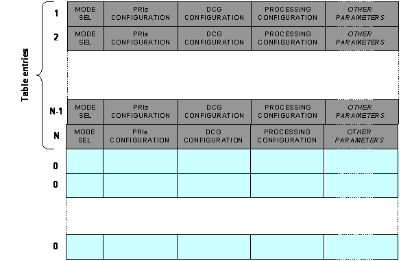
3.1. OPERATIONAL SEQUENCE
TABLE....................................................................................
3
SRQD.-3.1/010 Operational Sequence
Table...........................................................................................
3
SRQD.-3.1/020 Operational Sequence Default
values...........................................................................
4
SRQD.-3.1/030 Operational Sequence Table Entries
Format................................................................
4
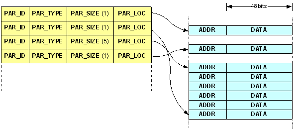
3.2. PARAMETERS
TABLE.......................................................................................................
9
SRQD.- 3.2/010 Parameters
Table..............................................................................................................
9
SRQD.- 3.2/020 Parameters Table
Categories.........................................................................................
9
SRQD.- 3.2/030 Parameters Table Value
Types......................................................................................
9
SRQD.- 3.2/040 Parameters Table Default
Values................................................................................
10
SRQD.- 3.2/050 Parameters Table
Content............................................................................................
11
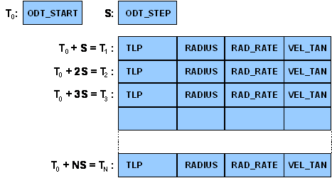
3.3. ORBITAL DATA
TABLE.....................................................................................................
15
SRQD.- 3.3/010 Orbital Data
Table...........................................................................................................
15
SRQD.- 3.3/020 Orbital Data Table Default
Values...............................................................................
15
SRQD.- 3.3/030 Orbital Data Table
Format.............................................................................................
16
4. EEPROM
LAYOUT...................................................................................................................
17