TABLE OF CONTENTS
Document Overview 2
1.0 SHARAD Measurements and Range Compression 2
2.0 Synthetic Aperture Processing 5
2.1 Overview of Processing 5
2.2 Processing Parameters 6
2.3 Radargram Quality 8
3.0 Processing Parameters and Ancillary Files 12
4.0 SHARAD-Specific PDS Keyword Parameters 15
5.0
References 16
Document Overview
This document describes SHARAD (Shallow Radar) sounding measurements, the steps used to process these data for the Planetary Data System archive produced by the U.S. science team, and specific keywords used in the detached labels. The primary image product associated with SHARAD observations is a radargram, where backscatter power is presented with along-track distance in the horizontal dimension and round-trip time delay along the vertical axis. Differences in the processing methods and resulting radargrams from the PDS archive products delivered by the SHARAD Italian science team are noted as appropriate. The Italian products are available as a separate PDS archive: http://pds-geosciences.wustl.edu/missions/mro/sharad.htm.
1.0 SHARAD Measurements and Range Compression
The Shallow Radar (SHARAD) sounder instrument on the Mars Reconnaissance Orbiter (MRO) is designed to detect subsurface reflections from dielectric changes associated with geologic interfaces and internal layering of the polar deposits. The sounder uses an 85.05-µs, frequency-modulated chirp (15-25 MHz) to increase the total power in the illuminating signal, and recovers a fine resolution in time delay by correlating the received echoes with a model for the transmitted waveform. The 10-MHz bandwidth yields a one-way range resolution in vacuum of 15 m, and vertical resolution of 5-8 m in typical geologic materials. Focused synthetic aperture processing is used to increase the coherent gain of the sounder and narrow the along-track resolution to 300-500 m [Seu et al., 2007]. The instrument dipole antenna is mounted parallel to the flight direction of MRO, and high along one side of the spacecraft bus. The presence of the bus and solar panels in the near field significantly distorts the beam pattern, and roll maneuvers up to about a 25o angle are performed to bring the peak of the beam pattern to nadir. In these rolled observations, the signal-to-noise ratio (SNR) of any given reflector may increase by up to several decibels (dB) over the nominal, nadir-pointed spacecraft geometry.
Each SHARAD measurement, or echo record, comprises 3600 real-valued samples of received voltage, transmitted to Earth after analog-to-digital (A/D) conversion. The range of the A/D conversion is adjusted, by reference to the signal level distribution, to properly sample the system noise and the received echoes from Mars with minimal clipping. The received voltages are sampled at 0.0375 µs intervals, forming a “delay window” 135 µs in duration. This corresponds to only 20.25 km in one-way path length through free space, so the beginning of the delay window must be shifted with respect to the start of each new transmit cycle to capture the echo from the surface of Mars and reflections from up to several km below the surface (Fig. 1). The delay-window start time, with respect to the initiation of each transmit cycle, is adjusted every 64 echo records by reference to a stored model of martian topography [Seu et al., 2007; Croci et al., 2011]. Raw echo records are collected with a pulse repetition frequency of 700.28 Hz. To limit data volume for transmission to Earth, on-board coherent pre-summing is usually performed. Typical on-board pre-summing factors are 4 or 8. Pre-summing may also be performed during ground processing. A raw experiment data record is in 8-bit format, with the effects of the automated A/D range operation compensated to provide a uniform amplitude reference. A lookup table is used to convert these values to floating-point data.
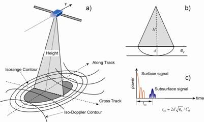
Fig. 1. SHARAD sounding observations. Panel (a) shows geometry of signal range and Doppler-shift variations relative to the MRO flight path. Panel (b) shows that signals from a given round-trip delay can arise from surface and subsurface locations. Panel (c) shows range-compressed signal, including strong sidelobes from mirror-like surface echoes. Similar sidelobes exist for subsurface reflections, but are often weak and not evident against the noise background.
In order to achieve the desired signal-to-noise performance, SHARAD employs a linear frequency-modulated chirp signal. The digital electronics deliver a uniform excitation to the power amplifier, but the actual transmitted signal differs from a flat amplitude behavior with frequency. The SHARAD antenna is a 10-m dipole, and even with a matching network its effective gain shifts over the 10-MHz chirp; this amplitude ripple is modestly affected by instrument temperature. A narrow pulse in delay is recovered (termed “range compression”) by correlating the received signal for each echo record with a model for the transmitted chirp. The particular model chirp must be further modified, as appropriate, to compensate for round-trip signal phase distortion due to the ionosphere. The chirp amplitude envelope and the method of ionospheric compensation differ between the U.S. and Italian PDS archive products as described below.
The Italian PDS radargram processing uses a range-compression step based on pre-launch measurements of the amplitude behavior of the antenna matching network as a function of transmitter and receiver temperature. These calibration files are in a form that yields a sampling interval of about 0.0659 µs in the range-compressed echo records (2048 complex-valued range samples from the original 3600 real-valued samples). Ionospheric effects are compensated by phase-gradient autofocusing (PGA), with a specified upper limit on the order of the phase distortion in frequency [Croci et al., 2011]. This results in a surface echo that is narrow in time delay, with low sidelobe levels.
The U.S. radargram processing uses a uniform amplitude model for the frequency components of the chirp. This leads to an asymmetric offset of the characteristic transform sidelobes, with greater sidelobe amplitude on the downrange (greater delay) side of any echo. The primary reason for this approach is to preserve a two-fold oversampling (i.e., 3600 complex samples from 3600 real samples) of the signal after range compression, which allows for flexibility in later interpolation. Ionospheric distortion is compensated using a model for the frequency dependence of the phase errors. The resulting correction term is approximately linear with total electron content (TEC), and thus with the change in delay time for signals from the surface and subsurface [Campbell et al., 2011, 2014]. The image-restoring and range corrections are applied where the solar zenith angle (SZA) is less than 100o. A Hann window function is applied to the frequency-domain data prior to the inverse Fourier transform to reduce sidelobe levels in the range-compressed echo.
2.0 Synthetic Aperture Processing
A single SHARAD echo record contains reflections from the surface and subsurface, but the broad antenna pattern combines returns from a large cross-track and along-track footprint, and yields only a modest signal-to-noise ratio for typical reflectors. Both aspects are improved by synthetic aperture processing. There are a variety of methods to implement the required resampling of the echoes in delay (range migration) and the compensation of phase (range-rate) variations over a coherent integration period, or synthetic aperture. Synthetic aperture radar processing exploits the fact that a given point on the ground is observed over a period of time as the sensor platform moves overhead. The change in Doppler frequency shift as a function of position within a set of sounder pulses allows for finer spatial resolution in the along-track direction. Synthetic aperture formation, substituting for a physically long antenna along track, requires detailed knowledge of the relative position and velocity of the sensor and target in order to properly sum echoes that vary in their time delay and phase. We describe below the steps used in the processing of these PDS products [see also Campbell et al., 2013].
2.1 Overview of Processing
The synthetic aperture is comprised of individual echo records for some number of sequential observations. To begin processing, the range-compressed data are assembled into a two-dimensional, complex-valued array, with round-trip delay along the vertical axis and along-track time on the horizontal axis. The first processing step is range migration, which aligns the delay locations in every echo record corresponding to a point on the surface at the center of the physical aperture. For the center record, there is thus no migration, and other echo records are shifted progressively uprange (since the center point appears at greater distance from the sensor) with increasing separation. Along any cut through the along-track time axis, the samples will now correspond to reflections from a point target, or a planar feature with no tilt in the along-track dimension. To the extent the surface or subsurface reflectors have a slope in the along-track axis, this step will misalign those signals and lead to blurring or artifacts in the final radargram.
The second step is often termed “azimuth compression”, and exploits Doppler shift information contained in the phase of signals, relative to the point target location, as the spacecraft moves through the physical aperture. We use the altitude, radial velocity, and tangential velocity information to determine a differential phase (with respect to the center) for each echo record. No significant variation is assumed to occur within any single record, and the phase function is based on the behavior of a point target at the MOLA-specified elevation of the surface. In principle, the phase correction can be applied as a function of frequency across the chirp bandwidth, but acceptable focusing performance is achieved by a phase correction scaled to the highest frequency component (25 MHz).
After the phase correction is applied, one vertical column of the radargram is produced by Fourier-transforming range-migrated “lines of equal delay” and taking the magnitude (or power) of the resulting frequency spectrum. A Hann window is used to reduce sidelobes in the azimuth compression. Properly range-migrated and phase-compensated reflections from various targets are thereby summed coherently to achieve substantial improvement in SNR. The isolation of the frequency components also serves to narrow the along-track resolution of the sensor by excluding echoes from targets beyond some limiting Doppler shift. We post radargram columns at 128 points per degree spacing (about 460 m along track), with the center (1800th) range cell corresponding to the free-space, round-trip time delay of the MOLA-defined Mars areoid. The output power value in each range cell of this radargram column is a sum over a chosen Doppler-frequency range about the zero-Doppler center of the spectrum. If the Doppler bin is wide enough to include more than one frequency resolution cell, then a multi-look product is created. After processing, there is no frequency or phase information; the radargram is only a measure of echo power.
2.2 Processing Parameters
Two basic parameters define the processing of SHARAD data. The first is the coherence time or aperture length, Tc (in seconds). The frequency resolution (in Hz) of the resulting Doppler spectrum is 1/Tc, independent of the time spacing between the pulses that make up the synthetic aperture. The degree of pre-summing, which reduces the pulse repetition frequency (PRF) from the initial value of 700.28 pulses per second, affects only the Doppler frequency bandwidth (in Hz) of the Doppler spectrum, which is given by 1/PRF. For example, the spectrum of SHARAD data in the presum-1 mode is about 700 Hz, and in the presum-4 mode is about 175 Hz.
The second parameter specifies the Doppler frequency bandwidth (in Hz), B, of echoes about the center of the Doppler spectrum to be included in the radar backscatter mapping. If this frequency width is less than 1/Tc, the output map will have only one sample for each output pixel location. This is a one-look radar image. If the frequency width is larger than 1/Tc, more than one Doppler resolution cell will be averaged, yielding a multi-look image. For the typical MRO tangential velocity and altitude, a 400-m ground resolution cell corresponds to ±0.3 Hz about the center of the spectrum. A bandwidth window of ±0.6 Hz will increase the number of looks, but effectively averages the radar echoes to an 800-m along track resolution.
The degree of pre-summing sets a practical limit on the length of the synthetic aperture by reducing the Doppler bandwidth of the data. At the two ends of the physical curve that corresponds to the synthetic aperture, a target point (at the center of the aperture) exhibits its most extreme Doppler shifts. These magnitudes cannot be greater than the width of the spectrum, 1/PRF, or the reflected signals from the edges of the aperture will fold over into the central region of the spectrum. Such aliasing is evident as bright V-shaped or isolated diagonal features in a radargram, often associated with steep slopes that create strong reflections at large Doppler shifts. Most of the SHARAD data were collected with an on-board pre-sum factor of 4, which allows for aperture lengths of up to about 50 s without significant aliasing of terrain with modest slopes. Some survey data were collected using the pre-sum factor of 8, which limits the coherent integration time to about 25 s even for gently undulating terrain (Fig. 2).
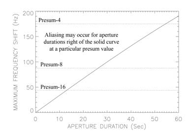
Fig. 2. Maximum Doppler frequency shift of signals that arrive at the two ends of a synthetic aperture, plotted versus the coherent integration time. The solid curve shows the limits related to aliasing of signals during azimuth processing. Intersections of solid curve and dotted lines indicate maximum aperture duration for chosen degree of pre-summing.
2.3 Radargram Quality
The “quality” of a radargram can be assessed on three characteristics:
(1) The signal-to-noise ratio of a planar, horizontal dielectric interface
(2) The degree to which sloping surface and subsurface interfaces are evident
(3) The standard deviation of the “speckle” noise background
The weighting given to these metrics can differ based on science goals. For example, we may choose to optimize parameters for SNR if the goal is to measure attenuation with depth or map subtle interfaces well below the surface. We may optimize sensitivity to sloping surfaces for studies of complex areas with significant changes in local slope, such as the troughs in polar layered terrain. Finally, we may choose to minimize speckle noise where horizontal spatial resolution is of less importance than maximizing the clarity of reflectors. We next consider the role of coherence interval and multi-look averaging on these radargram attributes.
Signal-to-Noise Ratio. We take as a baseline target a planar, horizontal patch (surface or subsurface) at least as large as the desired along-track resolution (300-500 m). The specular reflection from this target will peak as the sensor passes directly overhead, and decay rapidly to either side. Progressively rougher surfaces will scatter energy into a wider range of angles, but the strongest reflection will remain along the normal to the average plane. The angular width of this scattering pattern is important, so we define an angle θs, measured from the normal to the surface, as the point at which the specular echo equals the instrument noise level (SNR = 1). For the typical MRO altitude (285 km) and tangential velocity (3400 m/s), the coherence interval (in seconds) associated with this angular limit is Tc ≈ 168sinθs. Allowing the aperture to be longer, while increasing sensitivity to tilted reflectors and the potential for multi-look frequency resolution, reduces the SNR of echoes from planar, horizontal interfaces by adding pulses for which there is more noise than signal.
An example is a SHARAD observation of the North Polar Layered Deposits (NPLD) (observation 10589_01), which contains no major sources of clutter or extensive rough terrain such as dune fields. We document the change in total squared SNR across the radargram, as a function of Tc, with no multi-look averaging (just mapping the backscatter in the zero-Doppler cell). Normalizing to the noise in this analysis offsets the loss in backscattered signal that occurs as the frequency resolution narrows with Tc. The maximum radargram SNR is achieved when the aperture length is only 0.91 seconds (about 160 pulses in the pre-sum 4 mode, or θs of about 0.3o). A similar behavior was observed for tracks across the Elysium Planitia region with multiple planar subsurface horizons. In this configuration, the sounder data offer little sensitivity to sloping reflectors, and speckle is high due to the lack of averaging over the noise background. In general, science users have preferred a greater degree of sensitivity to sloping surface and subsurface interfaces in the radargram, but the longer apertures required to provide this yield progressively lower SNR on horizontal reflectors.
Geometric Sensitivity. The length of the physical aperture defined by Tc dictates the degree to which strong (e.g., specular) reflections from tilted interfaces can be observed in a radargram. The radar processing corrects the delay time and phase of pulses to either side of the aperture center by an amount consistent with a horizontal target patch. If an interface is tilted, the strong specular reflection will occur at greater range and/or along-track Doppler shift than the nadir location. These echoes will not be as well focused as horizontal patches (i.e., their SNR is lower), but they can occur in or near the center Doppler bin at their offset delay. Where the tilted interface is offset from and perpendicular to the ground track, the resulting echoes appear as “clutter”. Where the tilted features lie along the ground track, they appear as sloping reflectors connected to nearby flat-lying terrain. Mapping sloping interfaces in the radargram is often important to establish connections between groups of horizontal reflectors, or to trace the relationship of surface topography to the underlying layers.
As discussed, the angular width of the specular scattering lobe for a horizontal patch is narrow and longer integration times simply add noise to the observation. Longer integration times (larger physical apertures) are required, however, to allow the sounder to observe specular echoes from tilted features distant from the nadir point. Using the test track yields a progression of images with increasing coherence interval for single-look (zero-Doppler) data (Fig. 3). The images are stretched to an identical greyscale format with respect to the background noise. There is clearly a trade-off between deeper probing and delineation of sloping features.
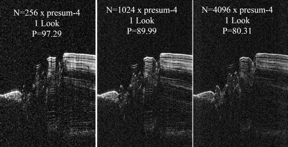
Fig. 3. SHARAD radargram for track 10589_01, processed using progressively longer coherence intervals (1.46 s, 5.85 s, 23.4 s). Note the increase in sensitivity to sloping surface and subsurface features, but significant SNR loss, with longer aperture. The P metric is the total of all squared SNR values across the scene (in dB).
Speckle Reduction and Spatial Averaging. Speckle is an inherent property of coherent imaging, where the standard deviation of any single measurement of the backscattered power is equal to the magnitude of the echo. Averaging N independent looks at the same target reduces the speckle noise by a factor of N-1/2. This yields a dramatic change in the noise background of a radargram, even for small numbers of total looks. The statistical fluctuations in individual interface echoes also decline, making reflecting horizons seem more laterally continuous. We can achieve speckle reduction in the radargram by averaging frequency-resolved bins within the chosen value of B (by increasing Tc), or by averaging along-track after forming the image.
A longer coherence interval allows increased sensitivity to sloping features, and offers the possibility for averaging of multiple independent looks to reduce speckle and modestly increase echo strength. For a specular, horizontal target these additional looks may be below the noise background, but incoherent averaging will yield an improvement in the overall SNR relative to using only the zero-Doppler bin. Reduction of the speckle variance is often desirable to clarify reflectors in published radargrams. Figure 4 shows the same three aperture configurations as before, but now allows for multi-look averaging at the expense of an 800-m horizontal spatial resolution (B=±0.6 Hz). Note that the shortest aperture remains a single-look product. The center image shows that, while echo strength from horizontal reflectors has been lost, the sloping reflectors of the third NPLD “packet” are more clearly delineated. The right-hand panel offers speckle reduction and detailed surface slope tracing, but a loss of SNR on deeper reflectors.
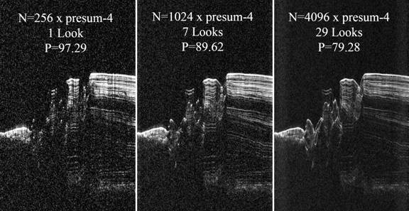
Fig. 4. SHARAD radargram for track 10589_01, processed using progressively longer coherence intervals (1.46 s, 5.85 s, 23.4 s) and multi-look averaging to 800-m along-track resolution.
3.0 PDS Processing Parameters and Ancillary Files
There is no single optimum configuration for processing SHARAD data, but radargrams for initial science studies should balance requirements for SNR, along-track spatial resolution, sensitivity to sloping surfaces and subsurface interfaces, and speckle reduction for clarity of feature mapping. Parametric studies suggest that an aperture length of 1536 samples at pre-sum 4 (Tc = 8.774 seconds), and a value of B=±0.4 Hz for 7 looks, offers a good balance. Figure 5 presents a comparison of a radargram with these parameters to the corresponding PDS archive product from the Italian team. Table 1 compares the processing parameters of the two archival radargram collections.
The Italian PDS archive products for SHARAD have been calibrated for the modeled variation in overall system response due to instrument temperature (which dictates the choice of chirp compression functions), solar array configuration, and high-gain antenna position. The U.S products do not implement any such corrections to this point, though future product releases may include a table of estimates for such gain variations. Information on the calibration steps used in the Italian PDS archive is provided in this and related documents: http://pds-geosciences.wustl.edu/mro/mro-m-sharad-3-edr-v1/mrosh_0001/calib/calibration_plan.pdf
Each 32-bit floating-point format radargram file in the U.S. PDS archive is accompanied by a TIFF image that logarithmically scales the backscattered power over an 8-bit range corresponding to -3 dB to +32 dB with respect to the noise background (i.e., each DN step is about 0.137 dB). The noise-scaling factor was determined from the average behavior over the period between orbits 7500 and 32999. Tracks collected before about orbit 7200 have a slightly higher (about 1.4 dB) background noise, so their TIFF radargram products will appear slightly brighter due to the use of the lower scaling factor.
A reduced-quality JPEG version of each TIFF is provided for browsing of the archive. Each radargram is also accompanied by an ASCII-format table file that contains location information for each radargram column, the spacecraft and surface radius values required to change the reference planetary shape, and the phase correction value related to the correction of ionospheric distortion and delay. The coordinate system is planetocentric, with longitude positive toward the east. Radius values tabulated in the GEOM files are interpolated using a polynomial fit between the along-track elapsed time and data from MOLA. The topographic information for the polynomial fit is drawn from the MOLA 128-ppd (pixels per degree) areoid gridded database for non-polar tracks, and from the 512-ppd gridded dataset for tracks that cross the polar terrain.
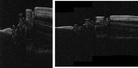
Fig. 5. (Left) Portion of U.S. PDS-format radargram for track 10589_01. (Right) Italian PDS-format radargram of the same track. Note difference in aspect ratio (about a factor of 2.7) due to the differences in vertical and horizontal resolutions (Table 1).
Table 1. Comparison Between U.S. and Italian Radargram Processing Parameters
|
Parameter |
U.S. Product |
Italian Product |
|
Chirp Envelope |
Uniform with frequency |
Ground Calibration |
|
Ionospheric Compensation |
Empirically derived function |
Phase gradient autofocus |
|
Aperture Length |
8.77 seconds |
1-2 seconds |
|
Along-track Posting |
128 ppd = 460 m |
300 m |
|
Delay Resolution |
0.0375 µs |
0.0659 µs |
|
Number of Looks |
7 |
1 |
4.0 SHARAD-Specific PDS Keyword Parameters
SYNTHETIC_APERTURE_DURATION
The coherent integration time (seconds) for SHARAD signals processed using the synthetic aperture technique. Multiplication of this value by the MRO tangential velocity tabulated in the GEOM.TAB files yields an approximate physical length of the aperture.
MULTILOOK_DOPPLER_BANDWIDTH
The frequency span (Hz) over which radar echoes are averaged, following synthetic aperture processing for each spatial footprint along the ground track. This frequency span is measured to either side of the zero-frequency component of the Doppler spectrum.
NUMBER_OF_LOOKS
The number of frequency-resolved cells included in the multi-look averaging. This varies with the chosen frequency span and the Doppler resolution set by the inverse of the coherent integration time.
CHIRP_FREQUENCY_ENVELOPE
The frequency-dependent amplitude variation used in range compression of the raw echo data. All radargrams in this archive use a uniform-amplitude model.
RANGE_COMPRESSION_WINDOW
The windowing function used to reduce sidelobes resulting from range compression of the raw echo records. All radargrams in this archive use a Hann function.
AZIMUTH_PROCESSING_WINDOW
The windowing function used to reduce sidelobes resulting from azimuth (along-track) synthetic aperture processing of the raw echo records. All radargrams in this archive use a Hann function.
PHASE/1.0E16
The scalar coefficient of an empirically derived phase distortion function used in suppression of ionospheric image blurring and delay offsets for solar zenith angles less than 100 degrees. A value for this coefficient is derived at intervals of about 23 seconds along the orbit track by optimizing a radargram image quality metric. The value used in the processing is reported here scaled by a factor of 1.0x10¹⁶.
5.0 REFERENCES
B.A. Campbell, N.E. Putzig, F.J. Foss, and R.J. Phillips, “SHARAD signal attenuation and delay offsets due to the martian ionosphere”, IEEE Geosci. Rem. Sensing Letters, vol. 11, 632-635, doi:10.1109/LGRS.2013.2273396, 2014.
B.A. Campbell, N.E. Putzig, L.M. Carter, G.A. Morgan, R.J. Phillips, and J.J. Plaut, “Roughness and near-surface density of Mars from SHARAD radar echoes”, J. Geophys. Res., vol. 118, doi:10.1002/jgre.20050, 2013.
B.A. Campbell, L.M. Carter, N.E. Putzig, and R.J. Phillips, “Autofocus correction of phase distortion effects on SHARAD echoes”, IEEE Geosci. Rem. Sensing Letters, vol. PP, issue 99, 939-942, doi:10.1109/LGRS/2011.2143692, 2011.
Croci, R., R. Seu, E. Flamini, and E. Russon, “The SHAllow RADar (SHARAD) onboard the NASA MRO mission”, Proceedings IEEE, vol. 99, 794-807, doi:10.1109/JPROC.2010.2104130, 2011.
R. Seu, R.J. Phillips, D. Biccari, R. Orosei, A. Masdea, G. Picardi, A. Safaenili, B.A. Campbell, J.J. Plaut, L. Marinangeli, S.E. Smrekar, and D.C. Nunes, “SHARAD sounding radar on the Mars Reconnaissance Orbiter”, J. Geophys. Res., vol. 112, no. E05S05, 2007. DOI:10.1029/2006JE002475.